Table of Contents
Advertisement
Advertisement
Table of Contents

Related Manuals for Gendex GXDP-700


Summary of Contents for Gendex GXDP-700
- Page 1 ENGLISH GXDP-700™ 3D Dental X-Ray System Installation Manual 206757 rev. 9...
- Page 3 Gendex Dental Systems. The original language of this manual is English. Gendex Dental Systems reserves the right to make...
- Page 4 GXDP-700™...
-
Page 5: Table Of Contents
Table of Contents Introduction........................1 1.1 GXDP-700™ ......................1 1.2 Intended use ......................2 1.3 Intended user profile ..................... 2 1.4 Associated documentation ..................2 1.5 References......................2 1.6 Abbreviations used in this manual ................ 3 1.7 Warnings and precautions ..................4 1.7.1 Warnings for cross infection............... - Page 6 Panoramic and 3D calibrations and adjustments........... 61 6.1 Introduction ......................61 6.2 When to calibrate the unit ................... 62 6.3 Reset maintenance counter ................63 6.4 Preparing for calibration ..................63 6.5 The calibration sequence ..................65 6.5.1 Calibration of the preheat of the tube............65 6.5.2 Calibration of the tube current..............
- Page 7 8.6.2.3 Manual update ................. 147 8.6.2.4 Verify and set the software version.......... 150 8.6.3 Configurable panoramic mAs limit ............151 GXDP-700 Pre-sales check list ................153 9.1 Physical Environment Requirements ..............153 9.2 Radiation Shielding Requirements..............153 9.3 Mechanical Specifications ................154 9.4 Electrical Specifications ..................
-
Page 9: Introduction
GXDP-700 is a dental X-ray system for producing high quality digital images of dentition, TM-joints and skull. In order to take images with GXDP-700, you need a suitable PC hardware connected to the GXDP-700 unit and imaging software to capture and manage images. -
Page 10: Intended Use
Only for professionally qualified dental / medical personnel. Typical user is a dental assistant with specific training for using dental x-ray units. 1.4 Associated documentation • GXDP-700 user manual • GXDP-700 installation manual • GxPicture Driver software installation manual •... -
Page 11: Abbreviations Used In This Manual
1 Introduction • 3D upgrade instructions are delivered with the 3D upgrade kit. 1.6 Abbreviations used in this manual FOV = Field Of View. The cylindrical 3D volume that is reconstructed by the system. ROI = Region Of Interest. The anatomical area or region of the patient that you are interested to examine. -
Page 12: Warnings And Precautions
1 Introduction 1.7 Warnings and precautions 1.7.1 Warnings for cross infection Always use available hygienic barriers with the patient posi- tioning accessories: • Bite guide hygienic barrier • Chin support hygienic barrier • Temple support hygienic barrier • Ear plug cover 1.7.2 Warnings to be observed during installation and service... - Page 13 1 Introduction If you have to leave the unit unattended with covers re- moved during servicing or maintenance, disconnect the unit from main power supply so that anyone who inadvertantly touches the unit does not receive an electric shock. This unit should only be used in areas that are provided with a protective earth connection to ensure an equipotential ground connection.
-
Page 14: Cautions For Electrostatic Discharge
1 Introduction 1.7.2.1 Cautions for Electrostatic discharge Electrostatic Discharge (ESD) can damage or destroy elec- tronic components. When servicing the device take precautions to avoid elec- trostatic build up and discharge (ESD). Follow the recom- mendations for the prevention of ESD that are used in the country in which you are working. - Page 15 1 Introduction The correct software and settings in the workstation are essential to the performance of the unit. Consult technical support to ensure correct setup. Danger: Explosion hazard - do not use in the presence of flammable anesthetics, gases or vapors. The unit is factory set to operate using a 230-240 ±10 VAC power supply.
- Page 16 1 Introduction When taking exposures, operators and service personnel must protect themselves from radiation and remain at least two meters (six feet) away from the unit during exposure. Protect the patient from scattered radiation by placing a protective lead apron over the patient. The unit must be installed and serviced according to the unit Installation &...
-
Page 17: Disclaimer
1 Introduction If this device is used with 3rd party imaging application software not supplied by the manufacturer, the 3rd party imaging application software must comply with all local laws on patient information software. This includes the Medical Device Directive 93/42/EEC and/or relevant legal requirements in the USA. - Page 18 1 Introduction...
-
Page 19: Unit Description
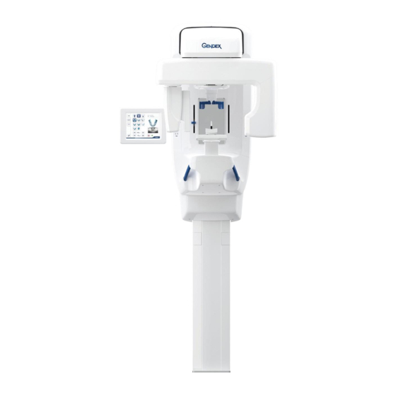
Unit description 2.1 Main parts and controls 1. Column 2. Carriage 3. Main support 4. Rotating unit 5. On / off switch (rear of car- riage) and main fuses 6. Tubehead assembly 7. Touchscreen display 8. Control panel 9. Sensor head 10.Head support 11.Chin rest 12.Handgrips... - Page 20 2 Unit description 1. Sensor holder (panoramic units without 3D option) 2. Panoramic sensor 1. 3D sensor (units with 3D option) 2. Panoramic sensor...
-
Page 21: Patient Positioning Lasers
2 Unit description 2.2 Patient positioning lasers 1. Midsagittal laser 2. Frankfort-horizontal plane laser (FH) 3. Image layer laser 4. Cephalometric Horizontal laser 5. TMJ laser 6. Horizontal laser, top of FOV (3D option only) 7. Horizontal laser, bottom of FOV (3D option only) - Page 22 2 Unit description Panoramic lasers 1. Midsagittal laser 2. FH laser (Frankfort Horizontal) 1. Image layer laser 2. TMJ laser...
- Page 23 2 Unit description Cephalometric lasers 1. FH laser (Frakfort Horizontal) 3D lasers (with 3D option) NOTICE! Appropriate lasers are turned automatically on based on selected FOV. 1. Midsagittal laser 2. Horizontal (H) light, top of FOV 3. Horizontal (H) laserlight, bottom of FOV...
-
Page 24: Control Panel
2 Unit description 2.3 Control panel 1. Patient In key - moves the Rotating Unit to allow patient better access when entering the unit. 2. Positioning lasers ON/OFF 3. Carriage UP 4. Carriage DOWN 5. Image Layer Control - Retrusion. 6. -
Page 25: Image Layer Controls
2 Unit description 2.3.1 Image layer controls Image Layer corresponds to the width of the x-ray capture area (focal trough) in relation to the position of the teeth. Typically, this trough completely encompasses the anterior teeth. However, in the case of a retruded bite, the teeth may be behind the trough. -
Page 26: Unit Identification Labels
2 Unit description 2.4 Unit identification labels 1. Main label 2. 10A & 15A Fuse labels (next to the fuse holder) 3. Laser class 1 warning label IEC 60825-1:2007 4. Ethernet label 5. Sensors 6. (Primary) collimator label 7. (Secondary) cephalostat collimator label 8. -
Page 27: Unit Movements
2 Unit description 2.4.1 Unit movements Panoramic unit movements... - Page 28 2 Unit description Cephalometric unit movements...
-
Page 29: Emergency Stop Switch
2 Unit description 2.5 Emergency stop switch In case of malfunction of the exposure button or other protective devices of the unit, an emergency stop switches are located near the handles and on the cephalostat unit, so that the patient can easily reach them. If the emergency stop switch is pressed during an exposure, the exposure is terminated immediately and the x-ray unit is completely stopped. - Page 30 2 Unit description...
-
Page 31: Pre-Installation Requirements
Pre-installation requirements 3.1 The unit ■ See chapter 9 Pre-sales check list. ■ The unit is supplied: GXDP-700 COLUMN MAIN SUPPORT CEPHALOSTAT Packages (card board) AND ROTATION (card board) UNIT (card board) Size (LxWxH) cm: 171 x 65 x 97 cm... - Page 32 3 Pre-installation requirements ■ Wall material should be suitable for fixing the unit. If the wall is made of weak material, you may have to use a reinforcing plate on the rear side of the wall to hold the fixing hardware. ■...
-
Page 33: Space Requirements
3 Pre-installation requirements 3.2 Space requirements When installing the unit make sure that: there is enough space at the front and sides of the unit to allow patients to enter and exit the unit eas- ily. Patients in wheelchairs will require more space than standing patients. - Page 34 3 Pre-installation requirements The type and length of hardware to be used depends on the wall material and floor material to which the unit is to be attached. Installation tools Electric drill Spanners (wrenches) 10, 17 (x 2) mm AF Allen keys (Hexagon socket wrenches) 1.5-8mm Flat blade screwdrivers Spirit level...
-
Page 35: Pc Requirements
PC requirements 4.1 Minimum PC requirements Minimum PC requirements for 3D acquisition workstation Processor 2.5 GHz dual core, or better Memory 8 Gigabytes RAM, or more Hard disk 500 GB, or more Power supply 500 watt minimum Network Gigabit Ethernet 1000Base-T Operating system Windows 7, Windows 8 / 8.1 or Windows 10 (64-bit) Display... - Page 36 4 PC requirements Minimum PC requirements for 2D acquisition workstation Processor 2.5 GHz dual core, or better Memory 3 Gigabytes RAM, or more Hard disk 500 GB, or more Graphics board NVidia GeForce 6600 or ATI Radeon X700 or better; 256MB or more memory (integrated graphics are not supported) Power supply...
- Page 37 4 PC requirements Minimum PC requirements for 2D/3D Viewing workstation * Processor 2.0 GHz dual core, or better Memory 3 Gigabytes RAM, or more Graphics board 1GB or more memory (integrated graphics are not supported) Hard disk 3 GB free space, or more Network Gigabit Ethernet 1000Base-T (recommended) or Fast Ethernet...
-
Page 38: The Dental Imaging Software
4 PC requirements with liquids. Clean the PC in accordance with the manufacturer’s instructions. The PC to be used with the unit must be installed in a location that meets all local and national safety requirements with regards the connection of a PC to an x-ray device. -
Page 39: Installing The Unit
Installing the unit NOTICE! Save the packaging materials as they may be needed if you move the unit to a new location. 5.1 Content of delivery MAIN SUPPORT AND COLUMN CEPHALOSTAT ROTATION UNIT (card board) (card board) (card board) ■ Column ■... - Page 40 5 Installing the unit Remove the plastic wrap. Remove the accessory boxes and the main support cover. Fold down the bottom end of the box and slide the unit over the edge of the pallet. Lift the front cover of the base plate off. Attach the wall bracket(s) to wall.
- Page 41 5 Installing the unit Adjustments: 1) angle 2) depth Additional wall bracket (lower) 3) lateral 4) vertical NOTICE! The unit is normally installed with one wall bracket (upper) and one base plate, which is bolted to the floor. If the unit cannot be bolted to the floor, an ad- ditional wall bracket (lower) or exhibition stand (206908) is required (ordered separately).
- Page 42 5 Installing the unit HEAVY OBJECT 71 KG 156.5 LBS A minimum of two persons are required for the following task. NOTICE! Follow the local regulations considering lifting heavy objects. Erect the column by lifting from the top. Move the unit to the place where it is installed and set it beside the wall.
- Page 43 5 Installing the unit 13. Remove the screws of the mains inlet cover and detach the cover. 14. Drill the floor and bolt the unit to the floor. If two wall brackets are used, tighten the lower one to the unit. 15.
- Page 44 5 Installing the unit 17. The default maximum height of the unit is 2440 mm. If the room height is less, the column maximum height must be adjusted. The height is adjustable from 2140 mm to 2440 mm by 60 mm steps. Adjust by changing the position of the microswitch.
- Page 45 5 Installing the unit d. Remove the EMC shield. e. Remove the right hand sheet metal bracket. f. Open 2 screws holding the microswitches “UP-LIMIT” and “HEIGHT-DET”. Move the microswitches to appropriate po- sition.
- Page 46 5 Installing the unit Microswitches “UP-LIMIT” and “HEIGHT-DET” are attached with the same screws. Microswitch UP-LIMIT is inside the cable guide. g. Re-install the removed parts and covers.
-
Page 47: The Carriage
5 Installing the unit 5.3 The carriage Transport the carriage box (number 1) to the location where the unit is to be installed. Remove the straps that hold the box to the pallet. Lift off the top of the box and then the sides. Remove the plastic wrap. - Page 48 5 Installing the unit Fold down the edges of the box. Fold the side parts of the styrofoam away, so that the end of the main support, that connects to the column, is fully accessible. Lift the carriage and push it towards the column. The lifting places are shown by arrows in the picture.
- Page 49 5 Installing the unit NOTICE! Do not put the carriage down on the chin rest or on the patient handles! Once the main support is pushed to its place, attach the indicated screw (M10 x 20mm) loosely on both sides of the main support to lock the main support in correct po- sition.
- Page 50 5 Installing the unit Attach two more screws (M10 x 20mm) on top of the main support and fasten all 4 screws to lock the main support to the column counterpart. 10. Tighten the two screws of step 8. 11. Remove the styrofoam material. 12.
-
Page 51: Check Leveling
5 Installing the unit 5.4 Check leveling Ensure the unit is level by adjusting the wall bracket(s). The wall bracket allows for the unit to be adjusted all directions. Before adjusting the tubehead must be turned to front position. Use the precision spirit levels on the top of the main support. -
Page 52: Connecting Internal Cables
5 Installing the unit 5.5 Connecting internal cables Attach the cables on both sides and top of the column. On the left side 1 Gigabit ethernet (JP004 marked with “Gigabit”) 2 Grounding point 3 Mains power cable On the right side On the top (Switch power cable pointed out) On the rear... -
Page 53: Attaching The Touch Screen Display To The Column (Old Model)
5 Installing the unit 5.6 Attaching the touch screen display to the column (old model) NOTICE! Old model is up to SN GE1503317, for newer unit models see chapter 5.7 Attaching the touch screen display to the column (new model). Unfasten the touch screen display arm (1 screw) and re-fasten it to the horizontal position. -
Page 54: Attaching The Touch Screen Display To The Column (New Model)
5 Installing the unit 5.7 Attaching the touch screen display to the column (new model) Unfasten the touch screen display arm (1 screw) from vertical position and re-fasten it to the horizontal posi- tion. One screw is pre-installed. Detach the two screws on the display arm joint. - Page 55 5 Installing the unit Fasten the touch screen display to the arm with the pre- viously detached screws. Detach the touch screen connector hatch. Connect the cables (Ethernet, PC power, the grounding cable). Secure the cable with cable clamp on the touch screen display bracket.
- Page 56 5 Installing the unit Attach the covers.
-
Page 57: Connecting The Mains Cable
5 Installing the unit 5.8 Connecting the mains cable Plug the supplied mains cable to the bottom of the col- umn. If additional Exposure button or External warning light need to be installed, do that before attaching the cov- ers. For more details, see chapters 5.9 Exposure but- ton and 5.10 Connecting the remote exposure switch. -
Page 58: Exposure Button
5 Installing the unit 5.9 Exposure button NOTICE! Exposure button is factory installed with a flexible spiral cable. The following installation is done only if other exposure button (optional) is needed. Attach the exposure switch holder to the rear of the touch screen display arm. -
Page 59: Connecting The Remote Exposure Switch
5 Installing the unit 5.10 Connecting the remote exposure switch NOTICE! The unit is shipped with an exposure switch connected to the device. Depending on the preference of the customer and the site layout, the Remote exposure switch (provided in shipment) may be needed in lieu of the factory connected switch. -
Page 60: Installing The Cephalometric Unit
5 Installing the unit 1. Strain relief location 2. External warning light cable 3. Cable connection J1004 4. Fuse holder F3 5.11 Installing the cephalometric unit NOTICE! Check the orientation of the nasion support and the ear holders so that the patient is always facing to the x- ray room. - Page 61 5 Installing the unit Lift off the top of the box and then the sides. Remove the plastic wrap. Cephalostat upgrade kit: Remove the accessory box. The accessory box con- tains all the bolts required in the cephalostat unit instal- lation.
- Page 62 5 Installing the unit CAUTION! Lift the cephalostat together with its packing cells. Keep the cells together. Place on a level ground. HEAVY OBJECT 25 KG 55 LBS NOTICE! Follow the local regulations considering lifting heavy objects. Attach the four cephalostat arm installation bolts to the back of the column.
- Page 63 5 Installing the unit NOTICE! If the cephalostat arm does not fit to its posi- tion, loose all four nuts and also two screws to fit the arm properly. Use a separate spirit level to check that the arm is straight. Adjust if needed. Take the cephalostat unit out of the styrofoam packag- ing and lift it carefully to the hook on the other end of the cephalostat arm.
- Page 64 5 Installing the unit zontal imbalance) or slightly hanging (side horizontal imbalance), straighten it as instructed below. Side horizontal adjustment (slightly hanging) Adjust. Loosen the screws. 1) Loosen three screws. 2) Lift the cephalostat head at the same time, when ad justing with the allen key, until the spirit level is levelled.
- Page 65 5 Installing the unit 1) Use wrench to loosen the two nuts, then adjust by turning the cephalostat head until the spirit level is lev- elled. 2) Re-tighten the nuts. Horizontal adjustment (rotated on horizontal level) NOTICE! This adjustment is done only, if the calibration does not pass and the cephalostat head needs to be ro- tated.
- Page 66 5 Installing the unit 1: Remove the jumper JB006. Attach signal/Power cable. 2: Ethernet cable 3: Grounding point 13. Before installing the upper cover, take a cephalostat calibration image according to the cephalostat calibra- tion instructions in this manual. Install the covers (5 pieces).
- Page 67 5 Installing the unit...
-
Page 68: Enabling Carpus Imaging
5 Installing the unit 14. Take the sensor out of its package and attach to the sensor holder. Make sure the sensor goes all the way down before pulling the lever. 15. Pull the lever down to lock the sensor to it’s place. 5.11.1 Enabling carpus imaging Type in s2terminal in service mode: “carpus enable”. -
Page 69: Panoramic And 3D Calibrations And Adjustments
Panoramic and 3D calibrations and adjustments 6.1 Introduction The calibration procedure helps to maintain image quality and correct operation of the unit. When carrying out the full or partial calibration procedure, the calibration and check steps must be carried out in the order in which they are listed. -
Page 70: When To Calibrate The Unit
6 Panoramic and 3D calibrations and adjustments performed as a support for the installer. All calibrations must be done until the system informs they are passed though. The fact that the exclamation marks disappear is just an indication of that the calibration program was started, not that the calibration was passed. -
Page 71: Reset Maintenance Counter
6 Panoramic and 3D calibrations and adjustments Panoramic panel After replacing the panoramic panel redo all the panoramic calibrations. If the collimator is adjusted or replaced, redo all collimator, pixel and geometry calibrations as well as the quality checks. 6.3 Reset maintenance counter 1. - Page 72 6 Panoramic and 3D calibrations and adjustments e) Press ENTER to open the s2terminal and make a connection to the unit. The s2terminal version number appears together with a list of commands. _______________________________________ ---- S2 Terminal Help ------------------------------------- help receive image from the device reserve device quit ------------------------------------------------------------------...
-
Page 73: The Calibration Sequence
6 Panoramic and 3D calibrations and adjustments 6.5 The calibration sequence 6.5.1 Calibration of the preheat of the tube NOTICE! Calibration of the preheat of the tube takes a while. The audible signal starts and stops several times. Do this calibration if there has been long time between installation and final testing of the unit or if the other calibrations won’t pass. -
Page 74: Calibration Of The Tube Current
6 Panoramic and 3D calibrations and adjustments 6.5.2 Calibration of the tube current NOTICE! Calibration of the tube current lasts very long. the audible signal starts and stops several times. Do this calibration if there has been long time between installation and final testing of the unit. -
Page 75: Collimator Calibration
6 Panoramic and 3D calibrations and adjustments 6.5.3 3D collimator calibration NOTICE! Only needed with 3D units. 1. Select the 3D Col program. 2. Press Patient Positioning. 3. Take an exposure. NOTICE! Adjust the height and tilt of the collimator manually. -
Page 76: Adjustment Of The Height And Tilt Of The Collimator
6 Panoramic and 3D calibrations and adjustments 6.5.3.1 Adjustment of the height and tilt of the collimator "BLD-NGEO-S" 1. Loosen four M4 nuts to be able to adjust the plate. 2. Adjust the height/tilt with two screws on the bottom of the collimator. -
Page 77: Bld-Ngeo-S
6 Panoramic and 3D calibrations and adjustments 6.5.3.2 Adjustment of the height of the collimator "BLD-NGEO-S-2" 1. Loosen two allen screws. 2. Adjust the height with two screws on the bottom of the collimator. Clockwise (cw) = Collimator upwards Counterclockwise (ccw) = Collimator downwards 3. -
Page 78: Beam Size Verification (Optional)
6 Panoramic and 3D calibrations and adjustments 6.5.4 3D Beam size verification (optional) This program can be used to verify that the size of the 3D X-ray beam does not exceed limits defined in IEC 60601-1- 3 and DIN 6868-161, if required by local regulations. The result of the program only gives information and does not affect the calibration of the unit. -
Page 79: Panoramic Collimator Calibration
6 Panoramic and 3D calibrations and adjustments 6.5.5 Panoramic collimator calibration NOTICE! With Pan unit (no 3D option) this calibration is done by adjusting the collimator (not the sensor), as in chapter 7.5.3.1-7.5.3.2, Adjustment of the height and tilt of the collimator. -
Page 80: Adjustment Of The Height Of The Pan Sensor
6 Panoramic and 3D calibrations and adjustments 6.5.5.1 Adjustment of the height of the PAN sensor NOTICE! This adjustment is only available on 3D devices. Do the adjustment with the sensor holder. 1. Remove the sensor. 2. Remove the sensor holder cover by removing four M4 screws. - Page 81 6 Panoramic and 3D calibrations and adjustments 3. Loosen five screws of the sensor holder. 4. Adjust the height with an adjustment screw on the bottom of the holder. Clockwise (cw) = Collimator upwards Counterclockwise (ccw) = Collimator downwards...
-
Page 82: Horizontal Adjustment Of The Collimator "Bld-Ngeo-S
6 Panoramic and 3D calibrations and adjustments 6.5.5.2 Horizontal adjustment of the collimator "BLD-NGEO-S" 1. Loosen four M4 nuts of the collimator. Move the collimator to the right or left. 2. Re-tighten the four M4 nuts and take a new image. NOTICE! 3D collimator calibration should be checked if the collimator is moved horizontally. -
Page 83: Horizontal Adjustment Of The Collimator "Bld-Ngeo-S-2
6 Panoramic and 3D calibrations and adjustments 6.5.5.3 Horizontal adjustment of the collimator "BLD-NGEO-S-2" 1. Adjust the Allen screw of the collimator. 2. Open the nut when adjusting the Allen screw. Hold the nut when adjusting the Allen screw. 3. Re-tighten the nut after Allen screw is adjusted. Take a new image. -
Page 84: Panoramic Geometry Calibration
6 Panoramic and 3D calibrations and adjustments 6.5.6 Panoramic geometry calibration 1. Select the Pan Geom program. 2. Press Patient Positioning. 3. Install the chin rest and double cone calibration tool. 4. Take an exposure. 5. Repeat the calibration until calibration result “passed” is achieved. -
Page 85: Geometry Calibration
6 Panoramic and 3D calibrations and adjustments 6.5.7 3D geometry calibration 1. Attach the base of the phantom to the lower shelf. Level it with the bubble on the adjustable phantom holder. 2. Install the 3D calibration phantom by placing a spirit level on top of the 3D calibration phantom. -
Page 86: Lasers Alignment
6 Panoramic and 3D calibrations and adjustments 6.5.8 3D lasers alignment Remove the mirror plate by loosening four M4 screws. Lift the plate first and pull. 1. Attach the 3D geometry calibration phantom to the unit. Use the 3D calibration phantom with grooves for aligning the FOV and mid-sagittal lasers. - Page 87 6 Panoramic and 3D calibrations and adjustments 5. Loosen the screw (B) of the upper laser. Align the tilt of the laser by rotating it.
- Page 88 6 Panoramic and 3D calibrations and adjustments 6. Loosen the two screws (C) of the bottom laser. Align the tilt of the laser by rotating. 7. Briefly press the exposure button (no X-rays are generat- ed) to acknowledge that the check has been carried out.
-
Page 89: Panoramic Laser Alignment
6 Panoramic and 3D calibrations and adjustments 6.5.9 Panoramic laser alignment 1. Attach the PAN geometry calibration tool (double cone) to the unit. 2. Select the Pan Lasers program. 3. Press Patient Positioning. 4. Remove the lower shelf bottom cover. 5. - Page 90 6 Panoramic and 3D calibrations and adjustments NOTICE! Lasers can be turned on by pushing the light button. Lasers stay on approx. 30 seconds. 6. Briefly press the exposure button (no X-rays are generat- ed) to acknowledge the adjustment has been carried out. The rotation and Y-position are also saved.
-
Page 91: Pixel Calibration
6 Panoramic and 3D calibrations and adjustments 6.5.10 3D pixel calibration 1. Remove all phantoms (if attached). 2. Select the 3D Pix program. 3. Press Patient Positioning. 4. Take an exposure. 5. The resulting image informs when the calibration is passed. -
Page 92: Panoramic Pixel Calibration
6 Panoramic and 3D calibrations and adjustments 6.5.11 Panoramic pixel calibration NOTICE! The pixel calibration results are sensor specific. If the x-ray unit is equipped with separate panoramic and cephalometric sensors, the cephalometric sensor cannot be used for panoramic imaging without re-calibration (and vice versa). -
Page 93: Quality Check
6 Panoramic and 3D calibrations and adjustments 6.5.12 3D Quality Check The x-ray unit has integrated 3D quality check program, which verifies following values from the reconstructed volume automatically: • Image noise • Grey values • Uniformity (Driver Update Package 15.1 or newer required) Following properties can be inspected visually by the user from the reconstructed volume:... - Page 94 6 Panoramic and 3D calibrations and adjustments 3. Press Patient Positioning. 4. Take an exposure. NOTICE! Reference your 3D imaging program manual for instructions on viewing the 3D volume. 3D QC program result evaluation NOTICE! Reference your 3D imaging program manual for instructions on viewing the 3D volume.
- Page 95 6 Panoramic and 3D calibrations and adjustments Pass/Fail calculation is based on ROI (Region of Interest) measurement result verification against reference values. “ROIs” smaller volumes inside reconstructed volume that are used to calculate noise or average grey values, for example. ROIs are marked with thin circular lines inside the reconstructed volume.
- Page 96 6 Panoramic and 3D calibrations and adjustments Grey values measurement Grey values of several materials in the reconstructed volume are measured. There must be difference in grey values in different materials to ensure adequate low contrast resolution and consequently to make sure that good tissue/bone separation is achieved in the 3D volume.
-
Page 97: Panoramic Quality Check (Optional)
6 Panoramic and 3D calibrations and adjustments Acceptable, shadowing may appear around straight horizontal material interfaces. Not acceptable; discontinuity in circular shape due to geometry mismatch between scans with different offset. In similar artefacts are observed, redo 3D geometry calibrations before retrying 3D QC. 6.5.13 Panoramic Quality Check (optional) 1. - Page 98 6 Panoramic and 3D calibrations and adjustments NOTICE! Not required in North America. NOTICE! Use the same tool for cephalostat Quality Check. 2. Select the Pan QC program. 3. Press Patient Positioning. 4. Take an exposure. 5. Visually evaluate the result using the installed imaging software.
- Page 99 6 Panoramic and 3D calibrations and adjustments Subjects to be evaluated: 1. Smoothness of the exposed area. Non-exposed area surrounds the whole image. 2. High contrast resolution; minimum 3.1LP/mm must be distinguishable. 3. All four low contrast holes must be visible. 4.
- Page 100 6 Panoramic and 3D calibrations and adjustments...
-
Page 101: Cephalometric Calibration And Alignment
Cephalometric calibration and alignment 7.1 Preparations NOTICE! The nasion support and the ear holders must be turned out of the way for cephalostat calibrations, so they are not in front of the x-ray beam. NOTICE! Check the orientation of the nasion support and the ear holders so that the patient is always facing to the x- ray room. -
Page 102: Balancing The Cephalostat
7 Cephalometric calibration and alignment 7.2.1 Balancing the cephalostat See chapter 5.10 Installing the cephalometric unit, step 11. 7.2.2 Primary collimator calibration 1. Attach cephalostat or pan sensor to the rotating unit sen- sor holder. 2. Touch Settings on the Touch screen display. 3. -
Page 103: Rotation Angle Calibration
7 Cephalometric calibration and alignment 7.2.3 Rotation angle calibration 1. Attach the cephalostat sensor to cephalostat sensor holder. 2. Open the ear holders and the temple holder as far as they go. 3. Select CEPH Rotate Angle calibration. 4. Press Patient In. 5. -
Page 104: Mechanical Adjustment Program
7 Cephalometric calibration and alignment 7.2.4 Mechanical adjustment program Mechanical adjustments of primary and secondary collimator, as well as adjustment of the cephalostat fixation angle, are guided by a mechanical adjustment program. This program gives an image with three exposed areas of interest (marked with arrows in the figure). - Page 105 7 Cephalometric calibration and alignment To complete this calibration: 1. Select the CEPH Mech Adj program. 2. Press Patient In. 3. Take an exposure. 4. Follow the instructions in the calibration result image. Possible instructions and references to further informa- tion are found in table “instructions for adjustment”.
- Page 106 7 Cephalometric calibration and alignment Table 7.1 Instructions for adjustment Instruction Additional information Move primary collimator UP/DOWN. The vertical position of the primary collimator must be adjusted in order to have the X-ray beam aligned to correct height. See chapter 8.2.4.1. Primary collimator vertical adjustment for details.
- Page 107 7 Cephalometric calibration and alignment Table 7.1 Instructions for adjustment Instruction Additional information Turn cephalostat head CW/CCW and redo Ceph Rot an- The fixation angle of the cephalostat gle calibration. must be adjusted in order to have the secondary collimator and sensor aligned with the X-ray source.
-
Page 108: Primary Collimator "Bld-Ngeo-S" Vertical Adjustment
7 Cephalometric calibration and alignment 7.2.4.1 Primary collimator "BLD-NGEO-S" vertical adjustment 1. Loosen the two locking nuts (black circles in the picture). 2. Adjust the vertical position of the collimator using the ad- justment screw (a white circle in the picture). Clockwise (cw) = Collimator upwards Counterclockwise (ccw) = Collimator downwards 3. -
Page 109: Primary Collimator "Bld-Ngeo-S-2" Vertical Adjustment
7 Cephalometric calibration and alignment 7.2.4.2 Primary collimator "BLD-NGEO-S-2" vertical adjustment 1. Loosen the locking nut. 2. Adjust the vertical position of the collimator using the ad- justment screw. Clockwise (cw) = Collimator upwards Counterclockwise (ccw) = Collimator downwards 3. Tighten the locking nut. -
Page 110: Cephalostat Fixation Angle Adjustment
7 Cephalometric calibration and alignment 7.2.4.3 Cephalostat fixation angle adjustment 1. Loosen two locking screws located in the bottom of the cephalostat, next to the cephalostat arm. 2. Slightly loosen two more locking screws, located next to the cephalostat arm. 3. -
Page 111: Removing Secondary Collimator Covers
7 Cephalometric calibration and alignment 7.2.4.4 Removing secondary collimator covers 1. Loosen the counter piece screws (2 pcs) through the holes in the cover. 2. Lift the cover to have it removed. 3. Remove the two lower screws and loosen the two upper screws (marked with arrows in the picture) to remove the second cover. -
Page 112: Secondary Collimator Vertical Adjustment
7 Cephalometric calibration and alignment 7.2.4.5 Secondary collimator vertical adjustment 1. Loosen four locking screws. Collimator vertical locking screws. 2. Adjust the vertical position of the lead plates using the adjustment screw. Vertical adjustment screw. 3. Tighten the locking screws. -
Page 113: Secondary Collimator Tilt Adjustment
7 Cephalometric calibration and alignment 7.2.4.6 Secondary collimator tilt adjustment 1. Loosen two locking screws. 2. Adjust the tilt of the secondary collimator using the tilt ad- justment screw. 3. Tighten the locking screws. -
Page 114: Secondary Collimator Horizontal Adjustment
7 Cephalometric calibration and alignment 7.2.5 Secondary collimator horizontal adjustment 1. Select Secondary Collimator Horizontal adjustment. 2. Press Patient In. 3. Take an exposure. 4. Repeat the calibration until calibration result “passed” is achieved. -
Page 115: Cephalostat Laser Alignment
7 Cephalometric calibration and alignment 7.2.6 Cephalostat laser alignment 1. Select the CEPH Lasers program. 2. Press Patient In. 3. Check that the laser beam is horizontal and that it goes through the center of the ear rod. 4. If the laser needs to be adjusted, loosen the screws of the laser shown on image and tighten it to its place when the laser is horizontal. -
Page 116: Cephalostat Pixel Calibration
7 Cephalometric calibration and alignment 7.2.7 Cephalostat pixel calibration 1. Attach secondary collimator and tubehead covers. 2. Rotate the ear holders into PA view position and move them completely apart. NOTICE! Turn nasion support up out of the way. 3. Select CEPH Pix Calibration program. 4. -
Page 117: Cephalostat Quality Check (Optional)
7 Cephalometric calibration and alignment 7.2.8 Cephalostat Quality Check (Optional) NOTICE! Not required in North America. NOTICE! Rotate the ear holders into PA view position. Turn nasion support up out of the way. 1. Attach the QC phantom to the cephalostat unit and en- sure that it’s leveled from the spirit level. - Page 118 7 Cephalometric calibration and alignment Subjects to be evaluated: 1. Smoothness of the exposed area. Non-exposed area surrounds the whole image. 2. High contrast resolution; minimum 3.1LP/mm must be distinguishable. 3. All four low contrast holes must be visible.
-
Page 119: Ear Holder Alignment
7 Cephalometric calibration and alignment 7.2.9 Ear holder alignment NOTICE! Rotate the ear holders into lateral view position and move them completely apart. Push nasion support as in as it go. The ear holder center pins and the x-ray focal spot must be in line. -
Page 120: Horizontal Adjustment
7 Cephalometric calibration and alignment 7.2.10 Horizontal adjustment Rotate the ear holder assembly to access to all locking screws. 1. Loosen the 4 locking screws (A) on the ear holder as- sembly. To ease the loosening, lock the ear holder assembly to its place with the Top view of ear holder assembly. -
Page 121: Vertical Adjustment
7 Cephalometric calibration and alignment 7.2.11 Vertical adjustment 1. Loosen the 4 locking screws (B) on the ear holder as- sembly. Top view of ear holder assembly. Vertical adjustment screw Locking screw (B) 2. Mark the starting position to the scale beside the screw. 3. - Page 122 7 Cephalometric calibration and alignment...
-
Page 123: Special Procedures
When updating the unit, e.g. with a cephalometric or 3D option, it is always recommended to update the unit with latest firmware and the image capturing PC with the latest driver software (Gendex Driver Update CD). Please contact Gendex Dental’s Technical Support for further information. -
Page 124: Changing The Cephalostat Arm Side
8 Special procedures 8.3 Changing the cephalostat arm side Left hand cephalostat arm is on the left when standing in front of the unit. In these instructions left handed cephalostat is changed to be right handed. Remove the upper cover (A) from the cephalostat head. - Page 125 8 Special procedures Remove the cables that go from the cephalostat head to the cephalostat arm. The cables can be left inside the arm. Loosen two screws, lift the cephalostat head and re- move it from the arm. Remove the cables that go from the arm to the column. On top of the unit column: 1: Signal/Power cable 2: Ethernet cable...
- Page 126 8 Special procedures NOTICE! There should be jumper JB006 connected to the connector JB006, when cephalometric unit is NOT installed. Remove the arm from the column (4 nuts).
- Page 127 8 Special procedures Disassemble the arm. Left handed cephalostat arm. Rotate the arm 180º with the cable inside. Re-assemble the arm from left handed to right handed (or vice versa when needed). Right handed cephalostat arm.
- Page 128 8 Special procedures Re-attach the cables from the column to the arm. 1: Signal/Power cable, 2: Ethernet cable, 3: Grounding point 10. Rotate the cephalostat head. Move the fastening plate of the cables to the other side of the cephalostat head. (Right handed assembly)
- Page 129 8 Special procedures 11. Move the bubble level to the other side of the cepha- lostat head. (Right handed assembly) 12. Re-route the cables from the sensor to the other side of the cephalostat head. (Right handed assembly)
- Page 130 8 Special procedures 13. Move the prism assembly to the other side of the ceph- alostat head. (Right handed assembly) Prism assembly for the left handed cephalostat.
- Page 131 8 Special procedures Prism assembly for the right handed cephalostat. 14. Move the 2 stop screws (A) to the other side so that when the patient is in the unit, they will be facing for- wards to the room. 15. Re-attach the cephalostat head to the arm.
- Page 132 8 Special procedures 16. Re-connect the cables from the arm to the cephalostat head. 17. Re-attach the cephalostat head upper cover, column top cover and carriage covers.
-
Page 133: Changing The Collimator
8 Special procedures 8.3.1 Changing the collimator Remove the covers by opening two screws on the bot- tom cover and the screws on the upper cover. - Page 134 8 Special procedures...
- Page 135 8 Special procedures Remove the plate by opening two screws (A) and loos- ening three screws (B).
- Page 136 8 Special procedures Unplug the motor cable. Cut the two cable ties. Unplug the Opto cable from the Opto board.
- Page 137 8 Special procedures Remove the collimator "BLD-NGEO-S" (4 screws).
- Page 138 8 Special procedures Remove the primary collimator assembly (2 screws). Remove the plate (4 screws).
- Page 139 8 Special procedures Attach the collimator “BLD-NGEO-S-2” with four screws. Remove the old cables. 204866...
- Page 140 8 Special procedures Cut the four cable ties 204791 204791 Location...
- Page 141 8 Special procedures 10. Attach new collimator cable and sensor optos. Other end attached, other end through. 208878 Sensor head optos...
- Page 142 8 Special procedures 11. Attach new collimator module (one connector per cable head). Other end attached, other end through. 210453...
- Page 143 8 Special procedures 210453 Collimator 12. Attach new collimator motor cable. Location 208877...
- Page 144 8 Special procedures 13. Attach new cable ties. 14. Attach the covers.
-
Page 145: Changing The Cephalostat Arm Side In Service Mode
8 Special procedures 8.3.2 Changing the cephalostat arm side in service mode Usage: unithandedness [main|ceph|all] [l|r] main: Sets handedness for main unit ceph: Sets handedness for cephalostat unit all: Sets handedness for both cephalostat and main units l: The GUI and/or cephalostat are on the left side of the unit r: The GUI and/or cephalostat are on the right side of the unit Use this to define the handedness options of the unit. -
Page 146: Changing The Mains Voltage
8 Special procedures 8.5 Changing the mains voltage WARNING! Only an authorized technician is allowed to perform the mains voltage change of the unit. WARNING! Do not connect the unit to the mains voltage until instructed to do so. NOTICE! Units are delivered from the factory with 230Vac line voltage settings. - Page 147 8 Special procedures Remove the cover (A) under the lower shelf. Remove the metal plate by loosening 4 screws. On the EA200 board there is a jumper (J1) for line volt- age selection. If you have 220-240Vac mains voltage, you should install jumper marked with 230Vac to the J1 position.
- Page 148 8 Special procedures Make sure that you have correct main fuses (F1 & F2) in the unit. ■ For 220-240Vac use two 10A fuses, type T10A H 250V (Littelfuse 326 010) ■ For 100-120Vac use two 15A fuses, type T15A H 250V (Littelfuse 326 015) Remove the screws of the mains inlet cover and detach the cover.
- Page 149 8 Special procedures Now the unit can be connected to the mains and be switched on. NOTICE! If the unit is moved to a new location, check that the voltage at the new location is the same as the unit is configured to. If not, the unit needs to be config- ured to that particular mains voltage.+...
-
Page 150: Preparing The Pc
Refer to the documentation supplied with the other components and devices for information on how to do this. NOTICE! At the time of writing this manual, GXDP-700 is supported in GxPicture through selecting the GXDP-700 unit option. If only the graphic card (GPU) was delivered with the device, install the GPU. -
Page 151: Configuring The Communication Link To The Pc
8 Special procedures 8.6.1 Configuring the communication link to the PC NOTICE! The unit shall be connected directly to the acquisition PC with an Ethernet cable. Connection through the LAN-network of the site is not allowed. Two network ports are needed in the PC in order to connect also to the site network. - Page 152 IP address for the unit from your local IP administra- tor. To modify IP address of GXDP-700: PC: Locate the Gendex GXDP-700 icon on the win- dows taskbar, right click and select "Multiroom" tab. Close Exam (Release Control key). Status changes to "Available".
-
Page 153: Firmware Update
Status changes as follow: - Configure - Disconnected - Available To connect to GXDP-700 with specific (default) IP ad- dress: PC: Locate the Gendex GXDP-700 icon on the win- dows taskbar, right click and select "Multiroom" tab. Close Exam (Release Control key). Status changes to "Available"... -
Page 154: Preparing For Update
8 Special procedures 8.6.2.1 Preparing for update For a typical update you need ■ The latest release package. ■ A host PC for performing the update. The host PC may be a separate PC (e.g. a laptop computer) or the image acquisition workstation. ■... -
Page 155: Automatic Update
8 Special procedures 8.6.2.2 Automatic update Press the F10 button and press enter, or type in manu- ally: xu R<ver_major>.<ver_minor> Example: xu R1.11 An automatic update of the embedded software is per- formed. Follow the instructions printed in the s2terminal prompt and wait for the update to complete. - Page 156 8 Special procedures Main CPU FPGA (R3220) core update Press the F2 button and press enter, or type in manu- ally: xcc r3220 R<ver_major>.<ver_minor> Example: xcc r3220 R1.11 This will start a R3220 core update. Wait until the soft- ware is transferred and the unit has restarted. Power off the unit before the countdown in the boot prompt ends.
- Page 157 8 Special procedures es printed in the s2terminal prompt. Try again in case of failure. Updating the R3400 firmware and core Press the F6 button and press enter, or type in manu- ally: xcc r3400 R<ver_major>.<ver_minor> Example: xcc r3400 R1.11 Wait for the software package to be transferred to the IO board.
-
Page 158: Verify And Set The Software Version
8 Special procedures Press the F7 button and press enter, or type in manu- ally: xfr GXDP700_CEPHR3210_R<ver_ major>_<ver_minor>.srec core Example: xfr GXDP700_CEPHR3210_R1_11.srec core Wait until the update is completed, power off and power on again. Do not enter safe mode like in main CPU R3220 update. -
Page 159: Configurable Panoramic Mas Limit
8 Special procedures Set the software release version by pressing F9, or by manually typing: pmode 0 <ver_major> <ver_minor> Example: pmode 0 1 11 The unit should reply: programming ended successfully, version now R1.11 This command makes the unit store the versions of the software components currently loaded, so that the va- lidity of the software release may be verified later. - Page 160 8 Special procedures...
-
Page 161: Gxdp-700 Pre-Sales Check List
9 GXDP-700 Pre-sales check list GXDP-700 Pre-sales check list Dealer Dealer contact person Clinic name Clinic contact person Clinic address Clinic tel. Clinic IT contact Targeted installation date Targeted application training date Signature & Date Sales person End user One copy to sales person and one copy to end user. -
Page 162: Mechanical Specifications
9 GXDP-700 Pre-sales check list 9.3 Mechanical Specifications (see image 1&2) Installation space: Pan/3D: Minimum installation space Depth: 1700 mm Width: 1500 mm Height: 2410 mm at minimum (max height adjustable from 2140 to 2410) End User/Dealer Cephalostat: Minimum installation space... -
Page 163: Networking Specifications
9 GXDP-700 Pre-sales check list 9.5 Networking Specifications APPROVAL LEVEL Does Modifi- Com- RESPONSIBILITY not meet cation ment needed specs 1Gb/s network to all The connection between the End User/Dealer components unit must meet volved with GXDP- EN60601-1 requirements. 700 system... -
Page 164: Other Information
9 GXDP-700 Pre-sales check list 9.9 Other information 3rd party 3D soft- Is imaging software going to ware: be used with existing 3rd party 3D software? NOTE: Direct link between im- aging software and 3rd party 3D software is available for the... -
Page 165: Notes / Comments
9 GXDP-700 Pre-sales check list 9.10 Notes / comments... -
Page 166: Image 1: Dimensions With Cephalostat
9 GXDP-700 Pre-sales check list 9.11 Image 1: Dimensions with cephalostat NOTICE! The cephalostat arm and the touch screen can be on either side (L/R). -
Page 167: Image 2: Dimensions Of Pan/3D Unit
9 GXDP-700 Pre-sales check list 9.12 Image 2: Dimensions of PAN/3D unit... - Page 168 9 GXDP-700 Pre-sales check list NOTICE! The touch screen can be on either side (L/R).
Need help?
Do you have a question about the GXDP-700 and is the answer not in the manual?
Questions and answers