Table of Contents
Troubleshooting

Related Manuals for Miller Multimatic 255


Summary of Contents for Miller Multimatic 255
- Page 1 OM-278174E 2021-12 Processes Multiprocess Welding Description Arc Welding Power Source And Wire Feeder Multimatic ® OWNER’S MANUAL For product information, Owner’s Manual translations, and more, visit www.MillerWelds.com...
- Page 2 We know you don’t have time to do it any other way. That’s why when Niels Miller first started building arc welders in 1929, he made sure his products offered long-lasting value and superior quality.
-
Page 3: Table Of Contents
Connecting 1-Phase Input Power ..................19 Wiring Optional 240 Volt Plug (119172) For Connection To Miller Welder/Generator With Split-Phase 240 Volt Auxiliary Power . - Page 4 TABLE OF CONTENTS Manual Program Mode ....................44 6-10 Using Optional MDX-250 EZ-Select ™...
-
Page 5: Section 1 - Safety Precautions - Read Before Using
SECTION 1 – SAFETY PRECAUTIONS – READ BEFORE USING Protect yourself and others from injury—read, follow, and save these important safety precautions and operating instructions. 1-1. Symbol Usage DANGER! – Indicates a hazardous situation which, if not avoided, will result in death or serious injury. The possible hazards are shown in the adjoining symbols or explained in the text. - Page 6 HOT PARTS can burn. WELDING can cause fire or explosion. � Do not touch hot parts bare handed. � Allow cooling period before working on equipment. Welding on closed containers, such as tanks, drums, or pipes, can cause them to blow up. �...
-
Page 7: Additional Hazards For Installation, Operation, And Maintenance
� Never weld on a pressurized cylinder — explosion will result. CYLINDERS can explode if � Use only correct compressed gas cylinders, regulators, hoses, damaged. and fittings designed for the specific application; maintain them Compressed gas cylinders contain gas under high and associated parts in good condition. -
Page 8: California Proposition 65 Warnings
� Have the installation regularly checked and maintained. � Be sure all equipment in the welding area is electromagnetically compatible. � Keep high-frequency source doors and panels tightly shut, keep spark gaps at correct setting, and use grounding and shielding to �... -
Page 9: Section 2 - Consignes De Sécurité - Lire Avant Utilisation
SECTION 2 – CONSIGNES DE SÉCURITÉ - LIRE AVANT UTILISATION Pour écarter les risques de blessure pour vous-même et pour autrui — lire, appliquer et ranger en lieu sûr ces consignes relatives aux précautions de sécurité et au mode opératoire. 2-1. - Page 10 � Porter un harnais de sécurité si l’on doit travailler au-dessus du � Ne pas souder des métaux munis d’un revêtement, tels que l’acier sol. galvanisé, plaqué en plomb ou au cadmium à moins que le revête- ment n’ait été enlevé dans la zone de soudure, que l’endroit soit �...
-
Page 11: Symboles De Dangers Supplémentaires En Relation Avec L'installation, Le Fonctionnement Et La Maintenance
� Ne pas couper ou souder des jantes ou des roues. Les pneus peu- Les CHAMPS vent exploser s’ils sont chauffés. Les jantes et les roues réparées ÉLECTROMAGNÉTIQUES (CEM) peuvent défaillir. Voir OSHA 29 CFR 1910.177 énuméré dans les peuvent affecter les implants normes de sécurité. - Page 12 � Suivre les consignes du Manuel des applications pour l’équation � Lorsque cela est nécessaire pour des travaux d’entretien et de dé- de levage NIOSH révisée (Publication Nº94– 110) lors du levage pannage, faire retirer les portes, panneaux, recouvrements ou dis- manuelle de pièces ou équipements lourds.
-
Page 13: Proposition Californienne 65 Avertissements
2-4. Proposition californienne 65 Avertissements AVERTISSEMENT – Ce produit peut vous exposer à des pro- Pour plus d’informations, consulter www.P65Warnings.ca.gov. duits chimiques tels que le plomb, reconnus par l’État de Californie comme cancérigènes et sources de malforma- tions ou d’autres troubles de la reproduction. 2-5. -
Page 14: Section 3 - Definitions
� Complete Parts List is available at www.MillerWelds.com SECTION 3 – DEFINITIONS Safe75 201 Do not fuel a hot engine. 3-1. Additional Safety Symbol Definitions Safe24 20 Warning! Watch Out! There are possible hazards as shown by the symbols. Safe82 201 Use lift eye to lift unit and properly installed accessories only, not gas cylinders. - Page 15 � Complete Parts List is available at www.MillerWelds.com Self Shielded Flux Wire Type Cored Arc Welding Gas Preflow (FCAW) Gas Metal Arc Wire Feed Spool Cold Jog (Inch) To- Welding (GMAW) ward Workpiecel Gas Metal Arc Welding (GMAW) Gas Postflow Pulse MIG/Gun Control OM-278174 Page 11...
-
Page 16: Section 4 - Specifications
Information About Default Weld Parameters And Settings NOTICE – Each welding application is unique. Although certain Miller Electric products are designed to determine and default to certain typical welding parameters and settings based upon specific and relatively limited application variables input by the end user, such default settings are for reference purposes only;... -
Page 17: Environmental Specifications
� Complete Parts List is available at www.MillerWelds.com 4-7. Environmental Specifications A. IP Rating IP Rating IP21 This equipment is designed for indoor use and is not intended to be used or stored outside. B. Temperature Specifications Operating Temperature Range* Storage/Transportation Temperature Range -22 to 122°F (-30 to 50°C) -40 to 149°F (-40 to 65°C) -
Page 18: Duty Cycle And Overheating For Mig
� Complete Parts List is available at www.MillerWelds.com 4-9. Duty Cycle And Overheating For MIG Duty Cycle is percentage of 10 minutes that unit weld rated load without overheating. If unit overheats, output stops. Wait fifteen minutes for unit to cool. Reduce amperage or duty cycle before starting to weld again. -
Page 19: Duty Cycle And Overheating For Stick
� Complete Parts List is available at www.MillerWelds.com 4-10. Duty Cycle And Overheating For Stick Duty Cycle is percentage of 10 minutes that unit weld rated load without overheating. If unit overheats, output stops. Wait fifteen minutes for unit to cool. Reduce amperage or duty cycle before starting to weld again. -
Page 20: Duty Cycle And Overheating For Tig
� Complete Parts List is available at www.MillerWelds.com 4-11. Duty Cycle And Overheating For TIG Duty Cycle is percentage of 10 minutes that unit weld rated load without overheating. If unit overheats, output stops. Wait fifteen minutes for unit to cool. Reduce amperage or duty cycle before starting to weld again. -
Page 21: Section 5 - Installation
� Complete Parts List is available at www.MillerWelds.com SECTION 5 – INSTALLATION 5-1. Selecting A Location Do not move or operate unit where Movement it could tip. Special installation may be re- quired where gasoline or volatile liquids are present - see NEC Ar- ticle 511 or CEC Section 20. -
Page 22: Electrical Service Guide
� Complete Parts List is available at www.MillerWelds.com 5-2. Electrical Service Guide Failure to follow these electrical service guide recommendations could create an electric shock or fire hazard. These recommen- dations are for an individual branch circuit sized for the rated output and duty cycle of one welding power source. In individual branch circuit installations, the National Electrical Code (NEC) allows the receptacle or conductor rating to be less than the rating of the circuit protection device. -
Page 23: Connecting 1-Phase Input Power
� Complete Parts List is available at www.MillerWelds.com 5-3. Connecting 1-Phase Input Power Installation must meet all National and Local Codes—have only quali- fied persons make this installation. Disconnect and lockout/tagout in- put power before connecting input conductors from unit. Follow es- tablished procedures regarding... -
Page 24: Wiring Optional 240 Volt Plug (119172) For Connection To Miller Welder/Generator With Split-Phase 240 Volt Auxiliary
� Complete Parts List is available at www.MillerWelds.com 5-4. Wiring Optional 240 Volt Plug (119172) For Connection To Miller Welder/Generator With Split-Phase 240 Volt Auxiliary Power 3 (Not Used) 1 Input And Grounding Conductors 2 Plug wired for 240 Volt, 2–wire Load... -
Page 25: Generator Or Inverter Requirements
Set Engine Control Switch to Run position, not Run/Idle. Set generator Voltage/Amperage Control to 10 (or max) for maxi- mum auxiliary power. For maximum output, Miller recommends a 12 kW or greater generator. Generator Settings, if applicable. 1 Engine Control Switch Setting 2 Generator... -
Page 26: Weld Output Terminals
� Complete Parts List is available at www.MillerWelds.com 5-7. Weld Output Terminals Turn off unit and disconnect input power before making connections. Do not use worn, damaged, under- sized, or repaired cables. 1 Positive (+) Weld Output Terminal 2 Negative (-) Weld Output Terminal See Section 5-9 for information on connect- ing to weld output terminals and standard connection diagrams. -
Page 27: Mig Welding Connections
� Complete Parts List is available at www.MillerWelds.com 5-9. MIG Welding Connections FCAW-S − DCEN MIG/FCAW-G − DCEP (Direct Current Electrode Negative) (Direct Current Electrode Positive) 5 Gun End Connect plug on end of cable to four pin re- Turn off unit and disconnect input ceptacle inside unit. -
Page 28: Mig Gun Connection Inside Unit
� Complete Parts List is available at www.MillerWelds.com 5-10. MIG Gun Connection Inside Unit 1 Gun Securing Knob 2 Gun Block 3 Gun Outlet Wire Guide 4 Gun End Loosen knob. Insert end of gun through opening in front panel until gun end bot- toms against gun block.Tighten knob. -
Page 29: Stick Welding Connections
� Complete Parts List is available at www.MillerWelds.com 5-11. Stick Welding Connections Turn off unit and disconnect input power before making connections. Do not use worn, damaged, under- sized, or repaired cables. 1 Positive Weld Output Receptacle 2 Negative Weld Output Receptacle 3 Stick Electrode Holder And Cable 4 Work Clamp And Cable Connect stick electrode holder cable to the... -
Page 30: Tig Welding Connections Dcen (Direct Current Electrode Negative)
� Complete Parts List is available at www.MillerWelds.com 5-12. TIG Welding Connections DCEN (Direct Current Electrode Negative) 280265B / Ref. 275167A / Ref. 280272C / 907728 / Ref. 273873 to positive weld output receptacle. Connect 8 Remote Control Cable Turn off unit and disconnect input TIG torch gas hose to gas hose fitting. -
Page 31: Connecting Shielding Gas Supply
� Complete Parts List is available at www.MillerWelds.com 5-13. Connecting Shielding Gas Supply Obtain gas cylinder and chain to running gear, wall, or other stationary support so cyl- inder cannot fall and break off valve. 1 Cap 2 Cylinder Valve Remove cap, stand to side of valve, and open valve slightly. -
Page 32: Installing Wire Spool And Adjusting Hub Tension
� Complete Parts List is available at www.MillerWelds.com 5-14. Installing Wire Spool And Adjusting Hub Tension Hand tighten knob clockwise. When a slight Installing 8 in. (203 mm) Wire Spool force is needed to turn spool, tension is set Removing 8 in. (203 mm) Spool Hub And Spool Nut 1 Spindle 2 Spool Hub And Nut —... -
Page 33: Threading Welding Wire
� Complete Parts List is available at www.MillerWelds.com 5-15. Threading Welding Wire 6 in. (150 mm) philips head wrench crescent wrench nutdriver chippinghammer WOOD uty workclamp 1 Wire Spool wirecutter frontcutter Step 5. Remove gun nozzle and contact tip. � Hold wire tightly to keep it from 2 Welding Wire Step 6. -
Page 34: Connecting Spoolmatic
� Complete Parts List is available at www.MillerWelds.com 5-16. Connecting Spoolmatic 15A Or 30A Or Spoolmate 200 Gun ® philips head wrench crescent wrench nutdriver chippinghammer 282999 Remove the 3/4 in. bolt from the drive cast- Align drill with pilot dimple in plastic bezel workclamp wirecutter frontcutter... -
Page 35: Connecting Xr-Aluma-Pro Or Xr-Aluma-Pro-Lite
� Complete Parts List is available at www.MillerWelds.com 5-17. Connecting XR-Aluma-Pro Or XR-Aluma-Pro-Lite 3/32 in. (2.4 mm) philips head wrench crescent wrench nutdriver 803463 / 282952A chippinghammer uty workclamp wirecutter frontcutter 4 Gun Securing Knob Be sure to change drive rolls to the proper 1 Gun End size and type. -
Page 36: Threading Welding Wire For Xr-Aluma-Pro Or Xr-Aluma-Pro Lite
� Complete Parts List is available at www.MillerWelds.com 5-18. Threading Welding Wire For XR-Aluma-Pro Or XR-Aluma-Pro Lite 6 in. (150 mm) philips head wrench crescent wrench nutdriver chippinghammer workclamp wirecutter frontcutter Press gun trigger until about 4 in. (102 mm) Step 1. -
Page 37: Threading Welding Wire For Spoolmate 200
� Complete Parts List is available at www.MillerWelds.com 5-19. Threading Welding Wire For Spoolmate 200 philips head wrench crescent wrench nutdriver chippinghammer Ref. 243 740-C uty workclamp wirecutter frontcutter 5 Pressure Roll Assembly Thread wire through wire inlet guide, along 1 Cover drive roll groove, and out contact tip. -
Page 38: Threading Welding Wire For Spoolmatic 15/30A
� Complete Parts List is available at www.MillerWelds.com 5-20. Threading Welding Wire For Spoolmatic 15/30A philips head wrench crescent wrench nutdriver chippinghammer 150 436-F workclamp wirecutter frontcutter Lift arm and open pressure roll assembly. Install spool so wire feeds off bottom. 1 Cover 7 Canister Inlet Guide 10 Spool Brake Thumbnut... -
Page 39: Calibrating Spoolgun
15/30A or Spoolmate 200 is connected � To begin the fast speed calibration, pull the to the Multimatic 255. SPG CAL will only be displayed as the spoolgun trigger. The wire will feed wire and fifth when... -
Page 40: Section 6 - Operation
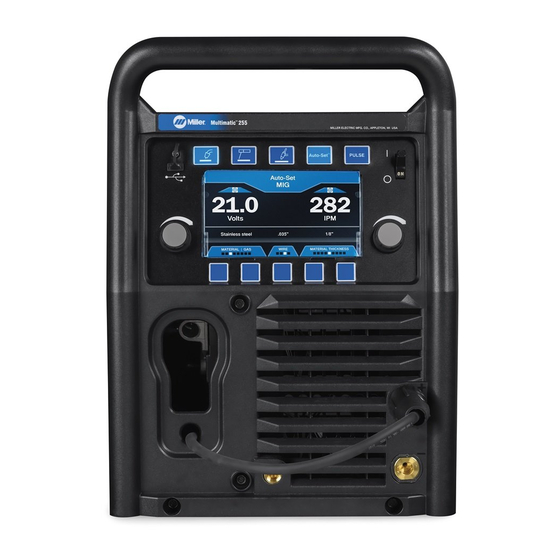
� Complete Parts List is available at www.MillerWelds.com SECTION 6 – OPERATION 6-1. Controls 277656-C Press to turn Pulse On or Off for MIG or TIG Use left knob to adjust voltage in MIG mode, 1 MIG Button process. Arc length in Pulsed MIG mode, pulse fre- quency in Pulsed TIG mode or change pa- Press to select MIG process. -
Page 41: Special Features
� Complete Parts List is available at www.MillerWelds.com 6-2. Special Features MIG Mode In MIG mode, the left knob is used to adjust welding voltage within a range of 12 to 32 volts. The right knob is used to adjust wire feed speed within a range of 50 to 800 IPM. Refer to weld chart inside the wire drive compartment for proper parameter settings according to wire type, shielding gas, and material type and thickness. -
Page 42: Using Auto-Set
� Complete Parts List is available at www.MillerWelds.com 6-3. Using Auto-Set Elite ™ 277656-C 6 Diameter Button Use right knob to fine tune wire feed speed 1 Process Buttons in MIG mode and amperage in Stick or TIG mode. Selects the size of the wire, rod, or tungsten Select desired welding process. -
Page 43: Using Manual Mode
� Complete Parts List is available at www.MillerWelds.com 6-4. Using Manual Mode 277656-C Press Program to save favorite weld pro- Use left knob to adjust voltage in MIG mode, 1 Process Button grams, up to four programs per weld proc- arc length in Pulsed MIG mode and pulse ess. -
Page 44: Manual Mig Set-Up Mode
� Complete Parts List is available at www.MillerWelds.com 6-5. Manual MIG Set-Up Mode 277656-C 1 Set-Up Button more fluid, softer arc. Decreasing induc- Crater: The amount of time the welding arc tance produces a stiffer arc. Inductance set- stays on after the welding gun trigger is re- 2 Left Knob tings range from 0 to 99. -
Page 45: Manual Stick Set-Up Mode
� Complete Parts List is available at www.MillerWelds.com 6-6. Manual Stick Set-Up Mode 277656-C Press Home to save settings and return to Disabled to 300%. The default hot start set- 1 Set-Up Button welding mode. ting is 100%. 2 Left Knob Items that can be adjusted from this menu Adaptive Hot Start: : Enabling Adaptive are:... -
Page 46: Manual Tig Set-Up Mode
� Complete Parts List is available at www.MillerWelds.com 6-7. Manual TIG Set-Up Mode 277656-C 1 Set-Up Button Items that can be adjusted from this menu In the Auto Postflow setting, gas will flow for are: one second for each 10 welding amps, up to 2 Left Knob 10 seconds. -
Page 47: Setting Crater Time
� Complete Parts List is available at www.MillerWelds.com 6-8. Setting Crater Time 277656-C The following Crater variables can be Crater Delay: This setting is for spot or 1 Left Knob adjusted: stitch welding without crater fill if the arc time is less than the set time. -
Page 48: Manual Program Mode
� Complete Parts List is available at www.MillerWelds.com 6-9. Manual Program Mode White Program tabs will appear above four Weld parameters may be changed while us- 1 Program Button of the soft keys. ing the program with the left and right knobs. If the settings are changed, the program tab 2 Program Soft Keys Determine where you would like to save the... -
Page 49: Using Optional Mdx-250 Ez-Select
� Complete Parts List is available at www.MillerWelds.com 6-10. Using Optional MDX-250 EZ-Select Gun In Program Mode ™ Ref. 800797-A When this feature is enabled, the 4 LEDs on Tap the trigger twice. LEDs 1 and 2 on the 1 Trigger Switch the MDX-250 gun handle indicate which pro- gun illuminate. -
Page 50: Pulsed Mig Auto-Set Mode
� Complete Parts List is available at www.MillerWelds.com 6-11. Pulsed MIG Auto-Set Mode ™ 277656-C Use soft key to select wire diameter. 50. Adjusting the Arc Length will vary the Pulsed MIG is a spray transfer that produces length of the welding arc cone. less heat input than conventional spray transfer, resulting in less warping, distortion, 6 Material Thickness... -
Page 51: Pulsed Mig Manual Mode
� Complete Parts List is available at www.MillerWelds.com 6-12. Pulsed MIG Manual Mode 277656-C 3, 6 required. Arc length will default to 50. Refer Arc Length can be adjusted to help custom- 1 MIG Process Button to Pulse MIG welding chart for proper Wire ize your arc to the gas being used. -
Page 52: Pulsed Tig Manual Mode
� Complete Parts List is available at www.MillerWelds.com 6-13. Pulsed TIG Manual Mode 277656-C 3, 6 6 Home Button Press Home to return to welding mode. The 1 TIG Process Button frequency can be adjusted on the home screen by rotating the left knob. Press TIG Process, and Set-Up buttons. -
Page 53: System
PPG: Press soft key to match the push-pull factory authorized service agents. Press soft key to return to Setup screen. gun being used. The selected gun, AlumaP- License: Press soft key to display Miller Li- ro or AlumaPro Lite, appears above the blue 2 Counters censing Agreement. -
Page 54: Support
Complete Parts List is available at www.MillerWelds.com 6-15. Support The support screen allows the operator to quickly access the Miller website and phone number to obtain more product information or get service support. Access the Support screen from the manual MIG screen by pressing Set-up, then Sup- port. - Page 55 Notes...
-
Page 56: Welding Parameter Chart - Mig
� Complete Parts List is available at www.MillerWelds.com 6-16. Welding Parameter Chart – MIG OM-278174 Page 52... - Page 57 � Complete Parts List is available at www.MillerWelds.com OM-278174 Page 53...
-
Page 58: Welding Parameter Chart - Stick And Tig
� Complete Parts List is available at www.MillerWelds.com 6-17. Welding Parameter Chart – Stick And TIG OM-278174 Page 54... - Page 59 � Complete Parts List is available at www.MillerWelds.com OM-278174 Page 55...
-
Page 60: Section 7 - Maintenance And Troubleshooting
� Complete Parts List is available at www.MillerWelds.com A complete Parts List is available at www.MillerWelds.com SECTION 7 – MAINTENANCE AND TROUBLESHOOTING SECTION 17 MAINTENANCE & TROUBLESHOOTIN mplete Parts List is available at www.MillerWelds.com 7-1. Routine Maintenance 17-1. Routine Maintenance Disconnect power before maintaining. -
Page 61: Aligning Drive Rolls And Wire Guide
� Complete Parts List is available at www.MillerWelds.com 7-4. Aligning Drive Rolls And Wire Guide Turn Off Power. View is from top of drive rolls looking down with pressure assembly open. Correct Incorrect 1 Drive Roll Securing Nut 2 Drive Roll 3 Wire Guide 4 Welding Wire 5 Drive Gear... -
Page 62: Error Messages
Internal temperature of welder has exceeded the Wait for unit to cool down. If the fan is not run- Overtemp-Please wait while the weld- maximum limit. ning, contact Miller Electric authorized service er cools down. location. Boost Module* Inverter Module * Out-... - Page 63 The primary boost has not successfully been Cycle power to clear error. If this error persists Boost Error established. after a power cycle, contact Miller Electric Mfg. authorized service location. Cycle power to clear error *Vbus Top High *Vbus Bottom High...
-
Page 64: Troubleshooting
Main transformer has detected an overcurrent Cycle power to clear error. If this problem per- lease trigger to clear OR cycle power condition. sists, contact Miller Electric Mfg. authorized serv- to clear. ice location. Missing UI Membrane Switch Overlay. UI membrane is not detected as being plugged Contact Miller Electric Mfg. -
Page 65: Section 8 - Parts List
� Complete Parts List is available at www.MillerWelds.com SECTION 8 – PARTS LIST 8-1. MDX-250 MIG Gun Consumables And Recommended Spare Parts See OM-282976 (shipped with this product) for information on replacement consumables for the MDX welding gun. 8-2. Drive Roll And Wire Guide Kits 1 V-Grooved rolls for hard wire. -
Page 66: Section 9 - Electrical Diagrams
SECTION 9 – ELECTRICAL DIAGRAMS Figure 9-1. Circuit Diagram OM-278174 Page 62... - Page 67 2798075-E OM-278174 Page 63...
-
Page 68: Section 10 - Gmaw Welding (Mig) Guidelines
SECTION 10 – GMAW WELDING (MIG) GUIDELINES 10-1. Typical GMAW (MIG) Process Connections 1 Wire Feeder/Welding Power Source 5 Gas Weld current can damage electronic parts in vehicles. Disconnect both 2 Gun 6 Shielding Gas battery cables before welding on a 3 Workpiece vehicle. -
Page 69: Holding And Positioning Welding Gun
Wire Size Amperage Range Recommended Wire Feed Speed Wire Feed Speed * 0.023 in. (0.58 mm) 30-90 A 3.5 in. (89 mm) per amp 3.5 x 62.5 A = 219 ipm (5.56 mpm) 0.030 in. (0.76 mm) 40-145 A 2 in. (51 mm) per amp 2 x 62.5 A = 125 ipm (3.19 mpm) 0.035 in. - Page 70 10-4. Conditions That Affect Weld Bead Shape Gun Angles and Weld Bead Profiles � Weld bead shape depends on gun an- gle, direction of travel, electrode exten- sion (stickout), travel speed, thickness of base metal, wire feed speed (weld current), and voltage. 1 Push 2 Perpendicular 3 Drag...
- Page 71 10-5. Gun Movement During Welding � Normally, a single stringer bead is sat- isfactory for most narrow groove weld joints; however, for wide groove weld joints or bridging across gaps, a weave bead or multiple stringer beads works better. 1 Stringer Bead - Steady Movement Along Seam 2 Weave Bead - Side To Side Movement Along Seam...
-
Page 72: Troubleshooting - Excessive Spatter
10-8. Troubleshooting – Excessive Spatter Excessive Spatter - scattering of molten metal particles that cool to solid form near weld bead. Possible Causes Corrective Actions Wire feed speed too high. Select lower wire feed speed. Voltage too high. Select lower voltage range. Electrode extension (stickout) too long. -
Page 73: Troubleshooting - Lack Of Penetration
10-11. Troubleshooting – Lack Of Penetration Lack Of Penetration - shallow fusion between weld metal and base metal. Possible Causes Corrective Actions Improper joint preparation. Material too thick. Joint preparation and design must provide access to bottom of groove while maintaining proper welding wire extension and arc characteristics. - Page 74 10-15. Troubleshooting – Distortion Distortion - contraction of weld metal during welding that forces base metal to move. Illustration: Base metal moves in the direction of the weld bead. Possible Causes Corrective Actions Excessive heat input. Use restraint (clamp) to hold base metal in position. Make tack welds along joint before starting welding operation.
- Page 75 10-17. Troubleshooting Guide For Semiautomatic Welding Equipment Problem Probable Cause Remedy Wire feed motor operates, but wire does not Too little pressure on wire feed rolls. Increase pressure setting on wire feed rolls. feed. Incorrect wire feed rolls. Check size stamped on wire feed rolls, re- place to match wire size and type if necessary.
-
Page 76: Section 11 - Stick Welding (Smaw) Guidelines
SECTION 11 – STICK WELDING (SMAW) GUIDELINES tools/ 11-1. Stick Welding Procedure wrench crescent wrench allen_set flathead philips head wrench crescent wrench Weld current starts when electrode Tools Needed: touches workpiece. Weld current can damage elec- tronic parts in vehicles. Discon- nect both battery cables before welding on a vehicle. - Page 77 11-2. Electrode And Amperage Selection Chart 6010 DEEP 3/32 MIN. PREP, ROUGH HIGH SPATTER 6011 DEEP 6010 5/32 & 6013 EP,EN GENERAL 3/16 6011 7/32 SMOOTH, EASY, 7014 EP,EN FAST 1/16 LOW HYDROGEN, 7018 5/64 STRONG 3/32 FLAT SMOOTH, EASY, 7024 EP,EN 6013...
- Page 78 11-4. Positioning Electrode Holder 1 End View Of Work Angle Groove Welds 2 Side View Of Electrode Angle After learning to start and hold an arc, prac- tice running beads of weld metal on flat 10 -30 10 -30 plates using a full electrode. Hold the electrode nearly perpendicular to the work, although tilting it ahead (in the di- rection of travel) will be helpful.
- Page 79 11-7. Conditions That Affect Weld Bead Shape Electrode Angle � Weld bead shape is affected by elec- trode angle, arc length, travel speed, and thickness of base metal. 1 Angle Too Small 2 Correct Angle 3 Drag 4 Angle Too Large 5 Too Short 6 Normal Arc Length...
- Page 80 11-9. Welding Lap Joints 1-1. Welding Lap Joints 1 Electrode 2 Single-Layer Fillet Weld 1-1. Welding Lap Joints Move electrode in circular motion. 3 Multi-Layer Fillet Weld Weld a second layer when a heavier fillet is needed. Remove slag before making anoth- er weld pass.
- Page 81 11-11. Welding T-Joints 1-3. Welding T-Joints 1/16 in. (1.6 mm) 1 Electrode 2 Fillet Weld Keep arc short and move at definite rate of speed. Hold electrode as shown to provide fusion into the corner. Square edge of the weld surface. For maximum strength weld both sides of up- 1-3.
- Page 82 Excessive Spatter - scattering of molten metal particles that cool to solid form near weld bead. Possible Causes Corrective Actions Amperage too high for electrode. Decrease amperage or select larger electrode. Arc length too long or voltage too high. Reduce arc length or voltage. Incomplete Fusion - failure of weld metal to fuse completely with base metal or a preceding weld bead.
- Page 83 Distortion - contraction of weld metal during welding that forces base metal to move. Illustration: Base metal moves in the direction of the weld bead. Possible Causes Corrective Actions Excessive heat input. Use restraint (clamp) to hold base metal in position. Make tack welds along joint before starting welding operation.
-
Page 84: Section 12 - Selecting And Preparing A Tungsten For Dc Or Ac Welding With Inverter Machines
SECTION 12 – SELECTING AND PREPARING A TUNGSTEN FOR DC OR AC WELDING WITH INVERTER MACHINES 12-1. Selecting Tungsten Electrode Whenever possible and practical, use DC weld output instead of AC weld output. NOTICE – Wear clean gloves to prevent contamination of tungsten. A. -
Page 85: Preparing Tungsten Electrode For Dc Electrode Negative (Dcen) Welding Or Ac Welding With Inverter Machines
1-1. Preparing Tungsten Electrode For DC Electrode Negative (DCEN) Welding Or AC Welding With Inverter Machines Grinding the tungsten electrode produces dust and flying sparks which can cause injury and start fires. 12-2. Preparing Tungsten Electrode For DC Electrode Negative (DCEN) Welding Or AC Use local exhaust (forced ventilation) at the grinder or wear an approved respirator. - Page 86 Notes...
-
Page 87: Warranty
Effective January 1, 2021 (Equipment with a serial number preface of NB or newer) This limited warranty supersedes all previous Miller warranties and is exclusive with no other guarantees or warranties expressed or implied. LIMITED WARRANTY − Subject to the terms and conditions TIG Torches (No Labor) below, Miller Electric Mfg. - Page 88 Appleton, WI 54914 USA tact your distributor and/or equipment manu- facturer’s Transportation Department. International Headquarters–USA USA Phone: 920-735-4505 USA & Canada FAX: 920-735-4134 International FAX: 920-735-4125 For International Locations Visit www.MillerWelds.com ORIGINAL INSTRUCTIONS – PRINTED IN USA © Miller Electric Mfg. LLC 2021-12...
Need help?
Do you have a question about the Multimatic 255 and is the answer not in the manual?
Questions and answers