Miller LMSW-52T Owner's Manual
Hide thumbs
Also See for LMSW-52T:
- Owner's manual (32 pages) ,
- Technical manual (32 pages) ,
- Owner's manual (28 pages)

Related Manuals for Miller LMSW-52T


Summary of Contents for Miller LMSW-52T
- Page 1 OM-708 029 805J April 1999 Processes Resistance Spot Welding Description MSW-41T, MSW-42T, And LMSW-52T Visit our website at www.MillerWelds.com...
- Page 2 – every power source from This Owner’s Manual is designed to help you get the most out of your Miller is backed by the most Miller products. Please take time to read the Safety precautions. They will hassle-free warranty in the business.
-
Page 3: Table Of Contents
TABLE OF CONTENTS SECTION 1 – SAFETY PRECAUTIONS ..........1-1. -
Page 5: Section 1 - Safety Precautions
SECTION 1 – SAFETY PRECAUTIONS - READ BEFORE USING spotom _nd_5/97 1-1. Symbol Usage Means Warning! Watch Out! There are possible hazards with this procedure! The possible hazards are shown in the adjoining symbols. Y Marks a special safety message. This group of symbols means Warning! Watch Out! possible ELECTRIC SHOCK, MOVING PARTS, and HOT PARTS hazards. -
Page 6: Additional Symbols For Installation, Operation, And Maintenance
MOVING PARTS can cause injury. FUMES can be hazardous. Coatings, cleaners, paints, and platings can pro- The tong tips, tongs, and linkages move during duce fumes when welded. Breathing these fumes operation. can be hazardous to your health. Keep away from moving parts. Do not breathe the fumes. -
Page 7: Section 2 - Introduction
(15.4 kg) (17.2 kg) 3/16 in 6 in 4-1/2 in 16 in 42 lb 45 lb LMSW-52T 2.5 kVA (4.7 mm) (152 mm) (114 mm) (406 mm) (19.1 kg) (20.4 kg) *Based on 10 second time period; means unit can weld for 5 seconds out of each 10 second time period. - Page 8 B. Dressing The Tips New Tip Used Tip Requiring Dressing Dressing Method – Keep top diameter same as a new tip. d = <1/8 in (3.2 mm) diameter for 1.5 kVA models; 5/32 in (4 mm) for 2.5 kVA models Tools Needed: OM-708 Page 4...
-
Page 9: Installing Or Cleaning Tongs
3-2. Installing Or Cleaning Tongs Y Turn off and unplug welder. Be sure tong ends are clean corroded before installing. Clean tongs with fine steel wool. Bottom Tong: Bottom Tong Hole In Spatter Guard Bottom Tong Securing Screws Loosen the four screws. If needed, use a rubber mallet to loosen tong. -
Page 10: Adjusting Tong And Hand Lever Pressure
3-3. Adjusting Tong And Hand Lever Pressure Tools Needed: 9/16, 11/16 in Ref. ST-800 156 Y Turn off and unplug welder. splash out around the nugget area. To decrease tong pressure, loosen the rear If tong pressure is too weak, parts are nut and turn the front nut up to the pivot cast- Y Excessive tong pressure can dam- loose when the tongs close, severe arc-... -
Page 11: Connecting Input Power
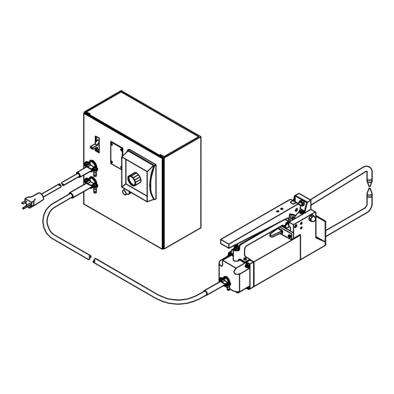
3-4. Mounting Control Box Push-in slots are provided on rear of box for wall mounting if desired. The slots will fit over 1/4 inch hex- head screws. To mount box, pro- ceed as follows: Control Box Push-In Slots (Not Shown) Use slots as template and install screws at desired locations leaving 1/8 inch stickout. -
Page 12: Section 4 - Operation
SECTION 4 – OPERATION 4-1. Controls Spot Weld Timer And Pilot Light Weld time adjusts from 0 to 5 seconds. The pilot light turns on when the weld cycle begins and off when the cycle ends. Hand Lever Use lever to open and close tongs. Close the hand lever during the welding process to compress the material between the tips. -
Page 13: Overload Protection For 220 Volts Model
5-2. Overload Protection For 220 Volts Model Y Turn Off unit and disconnect input power. If fuse opens, unit shuts down. To replace fuse, proceed as follows: Fuse Holder Cover Fuse F1 (See Parts List) Ref. ST-800 233 / Ref. ST-800 185-A 5-3. -
Page 14: Section 6 - Electrical Diagrams
SECTION 6 – ELECTRICAL DIAGRAMS SA-162 466-B Figure 6-1. Circuit Diagram For 110 Volts Models SA-072 065-B Figure 6-2. Circuit Diagram For 220 Volts Model OM-222 Page 10... - Page 15 Notes OM-708 Page 11...
-
Page 16: Section 7 - Parts List
SECTION 7 – PARTS LIST Hardware is common and not available unless listed. 38-Fig 6-2 ST-145 048-B Figure 7-1. Main Assembly OM-708 Page 12... - Page 17 Quantity Model Item Dia. Part Mkgs. Description Figure 7-1. Main Assembly ....019 643 HANDLE, carrying ........
- Page 18 Replace Coils At Factory Or Factory Authorized Service Station. Quantity Model Item Part Description Figure 7-2. Transformer, Power Main (Fig 7-1 Item 38) 095 345 095 350 095 354 ..026 601 INSULATION .
- Page 19 Quantity Model Item Dia. Part Mkgs. Description 115V 230V Figure 7-3. Timer, Spot (230V Illustrated) 041 081 041 082 ......NAMEPLATE, (order by model and style numbers) .
- Page 20 Chart 7-1. Spot Welder Tips 6” (152 mm) 040 197 3-1/2” (89 mm) Standard Flat 12” (305 mm) 040 198 18” (457 mm) 040 199 STANDARD 040 211 040 212 6” (152 mm) 040 200 3-1/2” (89 mm) Offset 12” (305 mm) 040 201 18”...
- Page 21 Notes...
- Page 22 Notes...
- Page 23 Effective January 1, 2000 (Equipment with a serial number preface of “LA” or newer) This limited warranty supersedes all previous Miller warranties and is exclusive with no other Warranty Questions? guarantees or warranties expressed or implied. Call LIMITED WARRANTY – Subject to the terms and conditions APT, ZIPCUT &...
- Page 24 Distributor Address City State For Service Call 1-800-4-A-Miller or see our website at www.MillerWelds.com to locate a DISTRIBUTOR or SERVICE AGENCY near you. Always provide Model Name and Serial/Style Number. Contact your Distributor for: Welding Supplies and Consumables Options and Accessories...
Need help?
Do you have a question about the LMSW-52T and is the answer not in the manual?
Questions and answers