
Related Manuals for Toro Groundsmaster 3320-D


Summary of Contents for Toro Groundsmaster 3320-D
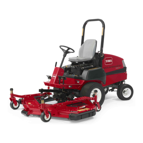
- Page 1 Form No. 3430-203 Rev A 60in Side Discharge Mower Groundsmaster ® 3320/3280-D Traction Unit Model No. 30366—Serial No. 403360001 and Up *3430-203* A Register at www.Toro.com. Original Instructions (EN)
- Page 2 This manual uses 2 words to highlight information. additional information, contact an Authorized Service Important calls attention to special mechanical Dealer or Toro Customer Service and have the model information and Note emphasizes general information and serial numbers of your product ready.Figure 1...
-
Page 3: Table Of Contents
Make all necessary repairs before resuming operation. • Keep all parts in good working condition and all hardware tightened. Replace all worn or damaged decals. • Use only accessories, attachments, and replacement parts approved by Toro. -
Page 4: Safety And Instructional Decals
Safety and Instructional Decals Safety decals and instructions are easily visible to the operator and are located near any area of potential danger. Replace any decal that is damaged or missing. decal93-6697 93-6697 1. Read the Operator's 2. Add SAE 80w-90 (API Manual. - Page 5 decal108-1986 108-1986 decal120-6604 120-6604 1. Height of cut 1. Thrown object hazard—keep bystanders away from the machine. 2. Cutting/dismemberment hazard of hand, mower blade—stay away from moving parts, keep all guards and shields in place. 3. Cutting/dismemberment hazard of foot, mower blade—stay away from moving parts, keep all guards and shields in place.
- Page 6 decal107-2916 107-2916 1. Remove the key and read the 2. Thrown object hazard—do not operate 3. Cutting/dismemberment hazard of Operator's Manual before performing the mower with the deflector up or hand or foot, mower blade—stay away maintenance. removed; lower the deflector before from moving parts.
-
Page 7: Setup
Setup Loose Parts Use the chart below to verify that all parts have been shipped. Procedure Description Qty. Pivot pin assembly Install the lift arms to the traction unit. Cotter pin Lift arm, right Lift arm, left Thrust washer-nylon Clevis pin Hairpin cotter—small Connect the lift arms to the cutting unit. -
Page 8: Installing The Lift Arms To The Traction Unit
Installing the Lift Arms to Connecting the Lift Arms to the Traction Unit the Cutting Unit Parts needed for this procedure: Parts needed for this procedure: Pivot pin assembly Lift arm, right Cotter pin Lift arm, left Thrust washer-nylon Procedure Clevis pin Hairpin cotter—small On one side of the traction unit, loosen (do not... -
Page 9: Replacing The Traction Unit Pto Shaft
Remove the cotter pin, bolts and locknuts securing the female end of the PTO shaft to the traction unit shaft. Remove the PTO shaft from the traction unit shaft and retain it for future applications. Install the female end of the PTO shaft, supplied with the cutting unit, to the traction unit shaft with the cotter pin. -
Page 10: Greasing The Machine
Contact your Authorized Service Dealer or authorized Toro distributor or go to www.Toro.com for a list of all approved attachments and accessories. To ensure optimum performance and continued safety certification of the machine, use only genuine Toro replacement parts and accessories. -
Page 11: Operation
Operation Note: Determine the left and right sides of the machine from the normal operating position. CAUTION If you leave the key in the ignition switch, someone could accidently start the engine decal100-5622 and seriously injure you or other bystanders. Figure 7 Remove the key from the ignition before you do any maintenance. -
Page 12: Adjusting The Rollers
Adjusting the Rollers Note: If the cutting unit is to be used in the 25 or 38 mm (1 or 1-1/2 inch) height-of-cut setting, the cutting unit rollers must be repositioned in the top bracket holes. To adjust the front rollers, remove the screw and nut securing the roller shaft to the deck bracket (Figure 10). -
Page 13: Adjusting The Skids
Adjusting the Skids Adjusting the Flow Baffle Mount the skids in the lower position when operating The mower discharge flow can be adjusted for in height of cuts higher than 64 mm (2-1/2 inches) and different types of mowing conditions. Position the cam in the higher position when operating in height of cuts locks and baffle to give the best quality of cut. -
Page 14: Adjusting The Cutting Unit Pitch
Adjusting the Cutting Unit Pitch Cutting unit pitch is the difference in height of cut from the front of the blade plane to the back of the blade plane. Use a blade pitch of 6 mm (1/4 inch), meaning that the back of the blade plane is 6 mm (1/4 inch) higher than the front. -
Page 15: Correcting A Cutting Unit Mismatch
Correcting a Cutting Unit DANGER Mismatch Without a grass deflector, discharge cover, or complete grass catcher assembly mounted in Due to differences in grass conditions and the place, you and others are exposed to blade counterbalance setting of the traction unit, it is advised contact and thrown debris. -
Page 16: Operating Tips
This also helps disperse clippings damage. Sharpen the blades as necessary. If a blade which enhances decomposition and fertilization. is damaged or worn, replace it immediately with a genuine Toro replacement blade. Refer to Removing and Installing the Cutting-Unit Blade(s) (page 21). -
Page 17: Maintenance
Maintenance Recommended Maintenance Schedule(s) Maintenance Service Maintenance Procedure Interval • Tighten the castor wheel nuts. After the first 2 hours • Tighten the castor wheel nuts. After the first 10 hours • Lubricate the castor arm bushings. Before each use or daily •... -
Page 18: Lubrication
Important: The fasteners on the covers of this machine are designed to remain on the cover after removal. Loosen all the fasteners on each cover a few turns so that the cover is loose but still attached, then go back and loosen them until the cover comes free. This prevents you from accidentally stripping the bolts free of the retainers. -
Page 19: Separating The Cutting Unit From The Traction Unit
g012237 Figure 24 1. Lift arm 3. Hairpin cotter 2. Clevis pin 4. Castor arm bracket g010548 Figure 22 Roll the cutting unit away from the traction unit, 1. Dipstick/fill plug separating the male and female sections of the PTO shaft (Figure 25). -
Page 20: Servicing The Castor Wheels And Bearings
is loose inside the bushings, the bushings are worn; To assemble the castor wheel, push the bearing replace them. into the wheel hub. When installing the bearings, press on the outer race of the bearing. Raise the cutting unit so that the wheels are off of the floor. - Page 21 Replace the blade if it hits a solid object, is out lifts the grass up straight, thereby producing an even of balance, or is bent. Always use genuine Toro cut and gradually wears down during operation. replacement blades to ensure safety and optimum performance.
- Page 22 Note: Remove the blades and sharpen them on a grinder. After sharpening the cutting edges, install the blade with the anti-scalp cup and blade bolt; refer to Removing and Installing the Cutting-Unit Blade(s) (page 21). g004653 Figure 30 1. Cutting edge 3.
-
Page 23: Checking And Correcting Mismatch Of Blades
Checking and Correcting Replacing the Drive Belt Mismatch of Blades The blade drive belt, tensioned by the spring loaded idler pulley, is very durable. However, after many If there is mismatch between the blades, the grass will hours of use, the belt will show signs of wear. Signs appear streaked when it is cut. -
Page 24: Replacing The Grass Deflector
decal108-1988 Figure 34 1. Belt routing g000977 Figure 35 1. Bolt 5. Spring installed Install the belt covers. 2. Spacer 6. Grass deflector 3. Locknut 7. L-end of spring, place Replacing the Grass behind the cutting unit edge before installing bolt Deflector 4. -
Page 25: Storage
Storage Disengage the PTO, release the traction pedal to the neutral position, lower the cutting unit, move the throttle lever to the S position, and engage the parking brake. Always shut off the engine, and remove the key. Wait for all movement to stop and allow the machine to cool before adjusting, cleaning, storing, or repairing it. - Page 26 The method of transmission shall be electronic transmittal. This machinery shall not be put into service until incorporated into approved Toro models as indicated on the associated Declaration of Conformity and in accordance with all instructions, whereby it can be declared in conformity with all relevant Directives.
- Page 27 While the exposure from Toro products may be negligible or well within the “no significant risk” range, out of an abundance of caution, Toro has elected to provide the Prop 65 warnings. Moreover, if Toro does not provide these warnings, it could be sued by the State of California or by private parties seeking to enforce Prop 65 and subject to substantial penalties.
- Page 28 Countries Other than the United States or Canada Customers who have purchased Toro products exported from the United States or Canada should contact their Toro Distributor (Dealer) to obtain guarantee policies for your country, province, or state. If for any reason you are dissatisfied with your Distributor's service or have difficulty obtaining guarantee information, contact your Authorized Toro Service Center.