Toro Groundsmaster 1200 Series Installation Instructions Manual
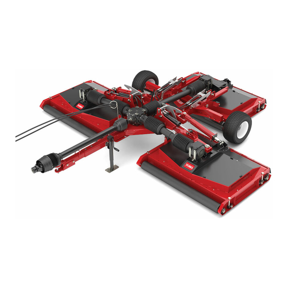
Fender kit pull behind rotary mower
Hide thumbs
Also See for Groundsmaster 1200 Series:
- Operator's manual (48 pages) ,
- Installation instructions (2 pages)
Advertisement
Quick Links
Fender Kit
Groundsmaster
Model No. 139-3174
Use of this product may cause exposure to chemicals known to the State of California
to cause cancer, birth defects, or other reproductive harm.
Safety
Safety and Instructional
Decals
Safety decals and instructions are easily visible to the operator and are located near any area
of potential danger. Replace any decal that is damaged or missing.
1. Warning—no step
© 2019—The Toro® Company
8111 Lyndale Avenue South
Bloomington, MN 55420
®
1200 Series Pull Behind Rotary Mower
Proposition 65 Warning
119-6807
Register at www.Toro.com.
WARNING
CALIFORNIA
decal119-6807
Form No. 3429-666 Rev A
Installation Instructions
Original Instructions (EN)
All Rights Reserved *3429-666* A
Printed in the USA
Advertisement

Related Manuals for Toro Groundsmaster 1200 Series


Summary of Contents for Toro Groundsmaster 1200 Series
- Page 1 Safety decals and instructions are easily visible to the operator and are located near any area of potential danger. Replace any decal that is damaged or missing. decal119-6807 119-6807 1. Warning—no step © 2019—The Toro® Company Register at www.Toro.com. Original Instructions (EN) All Rights Reserved *3429-666* A 8111 Lyndale Avenue South...
-
Page 2: Installation
Installation Loose Parts Use the chart below to verify that all parts have been shipped. Procedure Description Qty. – No parts required Prepare the machine. Fender Support tube Assemble the fenders. Flange-head capscrew (5/16 x 1-3/4 inches) Flange locknut (5/16 inch) –... - Page 3 Drilling the Axle Frame Tube No Parts Required Procedure g282354 Figure 1 1. Flange-head capscrew 3. Support tube g284106 (5/16 x 1-3/4 inches) Figure 2 2. Bracket (fender) 4. Flange locknut (5/16 inch) 1. Holes (axle frame tube) Assemble the other support tube to the other If your machine does not have holes in the axle frame fender bracket with 2 flange-head capscrews tube...
- Page 4 g284107 Figure 4 1. 11 mm (7/16 inch) drill bit g284109 Figure 3 Drill the centerpunch marks with a 11 mm (7/16 1. 51 mm (2 inches) 3. 44.5 mmm (1-3/4 inches) inch) drill bit (Figure 4) through both walls of the tube.
- Page 5 Torque the nuts and bolts to 1978 to 2542 N∙m (175 to 225 in-lb). Repeat steps through for the fender at the other side of the machine. Installing the Fenders onto the Machine Parts needed for this procedure: Capscrew (5/16 x 4 inches) Washer (5/16 inch) Flange locknut (5/16 inch) Procedure...
- Page 6 Notes:...
- Page 7 Notes:...