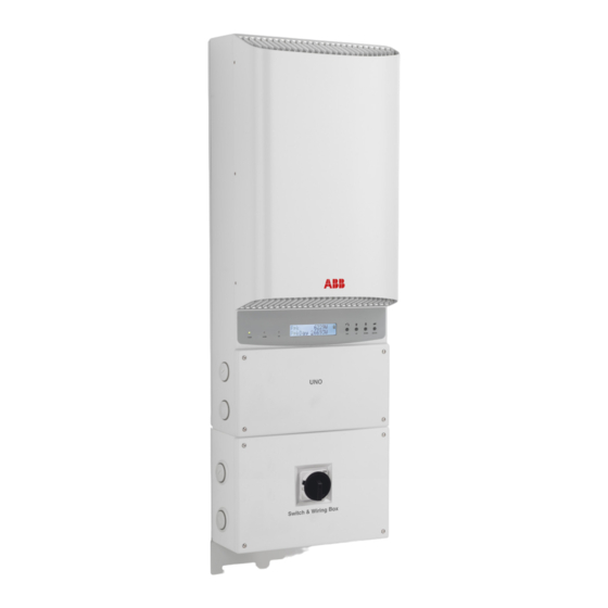
Summary of Contents for Power One PVI-5000-6000-OUTD-US
- Page 1 Page 1 of 92 The Manual: Revision: NA1. 0 PVI-5000-6000-OUTD-US The Manual: ______________________________________________________________________________ PVI-5000-6000-OUTD-US ______________________________________________...
- Page 2 Page 2 of 92 The Manual: Revision: NA1. 0 PVI-5000-6000-OUTD-US POWER-ONE Trademarks: Copyright © 2011 Power-One Renewable Energy Solutions, LLC. All rights reserved. No part of this document may be reproduced in any form or by any means without the prior written permission of Power-One Renewable Energy Solutions LLC.
-
Page 3: Table Of Contents
1.2 Selecting The Installation Location......................... 16 2a: 2.0 MOUNTING PVI-5000-6000-OUTD-US ................20 3.1 Removing the Front Covers ............................21 2a: 3.0 INSTALLATION PVI-5000-6000-OUTD-US ..............21 3.2 Electrical Wiring and Connections PVI-5000-6000-OUTD-US ..............21 3.2.1 Considerations Before Performing Electrical Connections ............. 22... - Page 4 Page 4 of 92 The Manual: 3.2.2 Field Wiring-Knockout- Details PVI-5000-6000-OUTD-US ..............22 Revision: NA1. 0 PVI-5000-6000-OUTD-US 3.2.3 Initial Electrical Connections PVI-5000-6000-OUTD-US ..............24 3.2.4 DC Array Connections ............................. 24 3.2.5 AC Grid Connections ............................26 Figure 2:07b: Grid Standard ............................ 26 3.2.6 Signal Wiring Connections ...........................
- Page 5 Page 5 of 92 The Manual: 2.5.4 Main Menu ..................................57 Revision: NA1. 0 PVI-5000-6000-OUTD-US 2.5.5 Statistics ..................................58 2.5.6 Lifetime ................................... 58 2.5.7 Partial ....................................58 2.5.8 Last 7 days ..................................59 2.5.9 Last Month ..................................59 2.5.10 Last 365 Days ................................60 2.5.11 User Period .................................
- Page 6 Page 6 of 92 The Manual: 1.2.1 Disconnection Of AURORA Inverter ........................76 Revision: NA1. 0 PVI-5000-6000-OUTD-US 1.3 CR2032 LITHIUM BATTERY REPLACEMENT ..............78 1.0 DATA SHEETS ..........................81 1.4.1 Fundamental Elements of a Photovoltaic System: 'STRINGS' and 'ARRAYS' ........88 1.4 DESCRIPTION OF THE SYSTEM ....................
- Page 7 Page 7 of 92 The Manual: Revision: NA1. 0 PVI-5000-6000-OUTD-US PART 1: INTRODUCTION & SAFETY...
-
Page 8: Instructions For Use Of This Manual
Page 8 of 92 The Manual: Revision: NA1. 0 PVI-5000-6000-OUTD-US INSTRUCTIONS FOR USE OF THIS MANUAL This manual contains important instructions for safety and operation that must be followed during KEEP THESE INSTRUCTIONS! installation and maintenance of this photovoltaic inverter. -
Page 9: Nameplate
Page 9 of 92 The Manual: Revision: NA1. 0 PVI-5000-6000-OUTD-US 2.2 Validity and Available Versions PVI-5000-OUTD-US 45.50" x 14.25" x 15.50"/ 1156mmX62mmX394mm Shipping Weight: 78 lbs Unit Weight: 75 lbs PVI-6000-OUTD-US 45.50" x 14.25" x 15.50"/ 1156mmX62mmX394mm Shipping weight: 78 lbs... -
Page 10: Maintenance And Service
The Manual: 2.4 MAINTENANCE AND SERVICE Revision: NA1. 0 PVI-5000-6000-OUTD-US The AURORA Inverter has no user-serviceable parts. Maintenance and service procedures must comply with the manufacturer's documentation. For more detailed information, please see Part 6 on Maintenance. 2.5 FIGURES AND IMAGES IN THIS MANUAL The photos in this manual may differ slightly from the final model shipped. -
Page 11: General Installation Warnings
Page 11 of 92 The Manual: Revision: NA1. 0 PVI-5000-6000-OUTD-US System earth conductor (main grounding protective earth, PE) Alternating Current (AC) Value ø Direct Current (DC) Value Phase Grounding (earth) The equipment has various labels. Those with a yellow background refer to safety concerns. Be sure to read all labels before beginning installation of the equipment. -
Page 12: Assembly Warnings
Page 12 of 92 The Manual: Revision: NA1. 0 PVI-5000-6000-OUTD-US In order to minimize the potential of a shock hazard due to hazardous voltages, cover the entire solar array with dark material prior to connecting the array to • any equipment. -
Page 13: Appropriate Usage
The Manual: 3.3 APPROPRIATE USAGE Revision: NA1. 0 PVI-5000-6000-OUTD-US The AURORA Inverter is a photovoltaic inverter that converts direct current of a PV array into alternating current and feeds that power into the power-distribution grid. This AURORA Inverter is suitable for outdoor installation only. -
Page 14: Location Of Safety Notices
Page 14 of 92 The Manual: Revision: NA1. 0 PVI-5000-6000-OUTD-US The inverter weight is about 75lbs and is susceptible to tipping. It requires two or more persons to mount to bracket. Use proper lifting techniques to avoid personal injury. CAUTION: Cuts and scratches due to sharp edges inside the AURORA Inverter. - Page 15 Page 15 of 92 The Manual: Revision: NA1. 0 PVI-5000-6000-OUTD-US PART 2: UNPACK & SELECT INSTALL LOCATION...
-
Page 16: Incoming Inspection
Page 16 of 92 The Manual: Revision: NA1. 0 PVI-5000-6000-OUTD-US 1.0 UNPACK AND INSPECT Install the AURORA Inverter in accordance with the electrical standards prescribed by the applicable National Electric Code and/or by other local regulations and codes. • Do not connect an AURORA Inverter to the electrical distribution grid until after receipt of a letter of authorization from the authority having jurisdiction. - Page 17 Page 17 of 92 The Manual: Revision: NA1. 0 PVI-5000-6000-OUTD-US 6. When possible, mount the AURORA Inverter vertically. For other mounting orientations consult with Power-One. 7. Tilted mounting (±5° from vertical) is acceptable, but will reduce heat dissipation and may result in self- derating.
- Page 18 Page 18 of 92 The Manual: Revision: NA1. 0 PVI-5000-6000-OUTD-US PART 3: MOUNTING & WIRING Section 1: PVI-5000-6000-OUTD-US Section 2: WIRING DETAILS Read and apply all safety warnings when performing these tasks.
- Page 19 Page 19 of 92 The Manual: Revision: NA1. 0 PVI-5000-6000-OUTD-US SECTION 1: PVI-5000-6000-OUTD-US...
-
Page 20: 2A: 2.0 Mounting Pvi-5000-6000-Outd-Us
The Manual: Revision: NA1. 0 PVI-5000-6000-OUTD-US 2a: 2.0 MOUNTING PVI-5000-6000-OUTD-US Figure 2:01 Bracket and Mounting Details Locate and mark the desired mounting location as shown above in mounting location. Orient the bracket such that the “C” hooks face outward and upward (Figure.2:01)


Need help?
Do you have a question about the PVI-5000-6000-OUTD-US and is the answer not in the manual?
Questions and answers