
Related Manuals for Landis+Gyr CASHPOWER SABRE MK 5


Summary of Contents for Landis+Gyr CASHPOWER SABRE MK 5
- Page 1 Prepayment Electricity Metering System D O M E S T I C Landis+Gyr C A S H P O W E R S A B R E M K 5 U S E R ’ S G U I D E...
-
Page 2: Set 2 Nd Dispenser Key Voucher
Updated for new Landis+Gyr branding and update of product pictures Abstract This document is the User Guide for the Cashpower Sabre Mk5 Common Base keypad prepayment meters, designed and developed by Landis+Gyr (Pty) Ltd., South Africa Referenced Documents None Landis+Gyr (Pty) Ltd. -
Page 3: Table Of Contents
Table of Contents 1. INTRODUCTION 2. ABBREVIATIONS 3. FRONT PANEL LAYOUT 3.1. Keypad 3.2. Liquid Crystal Display (LCD) 3.3. Rate of Consumption Indicator (Rate LED) 3.4. Meter Label Set 3.5. Anti-tamper sealing clips 4. LIQUID CRYSTAL DISPLAY (LCD) 4.1. Layout (what the icons mean) 4.2. - Page 4 5.10.3. Reverse Energy Detection 5.10.4. Magnetic Tamper Detection 5.10.5. Resetting a Tamper Condition 5.11. Virtual Token Carrier (VTC) Interface 6. INFORMATION FUNCTIONS 6.1. Meter Number (Register 000) 6.2. Instantaneous Power (Register 001) 6.3. Current Credit Register (Register 002) 6.4. Total Units Counter (Register 003) 6.5.
-
Page 5: Introduction
1. INTRODUCTION Cashpower Sabre ED Mk5 is a single phase “common base” prepayment meter specially designed to meet Eskom's prepayment metering requirements. This meter is most suited to new reticulation and is directly and easily interchangeable with meters from other manufacturers using the standard common base. -
Page 6: Front Panel Layout
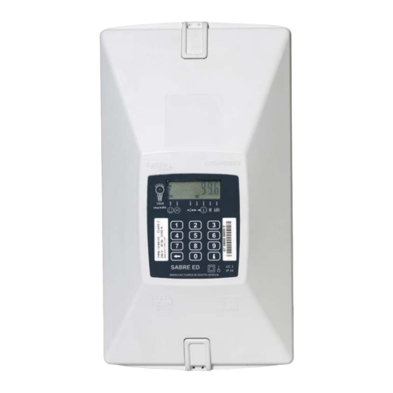
3. FRONT PANEL LAYOUT The Sabre front panel comprises a non-tactile, 12-key keypad with audible feedback for the entry of tokens and accessing of various information registers, and a custom Liquid Crystal Display Anti tamper sealing clip Membrane with keypad and icon display indicators Liquid Crystal Display (LCD) -
Page 7: Keypad
3.1. Keypad The 12-key keypad enables the entry of vouchers and the accessing of various information registers. Key-presses are acknowledged with an audible beep. 3.2. Liquid Crystal Display (LCD) The LCD normally displays remaining credit. The LCD also displays the scrolling in of keypad entries and various information functions. -
Page 8: Liquid Crystal Display (Lcd)
4. LIQUID CRYSTAL DISPLAY (LCD) 4.1. Layout (what the icons mean) The LCD is designed to give a clear and unambiguous visual indication of the important meter functions by means of language-independent pictograms. The LCD has three functional blocks: a numerical display for displaying various values such as remaining credit and power limit level, various pictograms such as the credit wedge, and pointers which point to pictograms on the membrane. -
Page 9: Typical Operational Displays
4.2. Typical Operational Displays 4.3. Happy and Sad Faces These two icons are used in combination to give a quick visual indication of good and bad status. For example, if the meter were operating normally, the happy face would be on. However, if it were to be tampered, the sad face would come on. -
Page 10: Information Mode Indicator
4.5. Information Mode Indicator This icon turns on in response to pressing the i-key on the keypad. It indicates that the meter is in information mode and the contents of various registers can be viewed. Refer to paragraph 6. 4.6. Power Indicator (W) This function is used whenever the displayed units represent power (W), such as instantaneous power, or power limit setting. -
Page 11: Meter Operation
5. METER OPERATION 5.1. General In this section the features and functionality of the prepayment meter are described in detail. 5.2. LCD Indications During Normal Operation During normal operation, the LCD provides the following indications: • Displays the current credit register value to a resolution of 0.1 kWh. •... -
Page 12: Voucher Processing
Figure 4: Typical Happy & Sad face combinations 5.4. Voucher Processing Depending on the type of voucher entered into the meter, it will result in one of the display sequences described below: 5.4.1. Incomplete Voucher A voucher entry is timed out if no key is pressed for more than 30 seconds. On time- out: •... -
Page 13: Complete Voucher
5.4.2. Complete Voucher If a complete voucher is entered, the meter: • Locks the keypad. • Proceeds to process the voucher number. • Unlocks the keypad. Depending on the result of the processing, one of the following sequences can occur: 5.4.2.1. -
Page 14: Voucher Decryption And Processing
5.5. Voucher Decryption and Processing The meter accepts information transferred as specified in the Standard Transfer Specification release 1.0:1995 with key typing included. Key expiry is not implemented. STS vouchers comprise of 20-digit numbers. The following STS voucher types will be recognised and accepted: •... -
Page 15: Set Power Limit Voucher
On completion of the test sequence, the meter returns to its normal mode of operation. 5.5.1.9. Commissioning Voucher (Non Meter-Specific, Proprietary Voucher) This is a non meter-specific voucher i.e. it can only be used on Landis+Gyr STS meter: 1268 2136 5508 1001 3746... -
Page 16: Commissioning Voucher (Meter-Specific, Proprietary Voucher)
5.5.1.10. Commissioning Voucher (Meter-Specific, Proprietary Voucher) This is a meter-specific voucher but in all other aspects its operation is the same as described in paragraph 5.5.1.9. Note: An already commissioned meter rejects a commissioning token. 5.5.1.11. Decommissioning Voucher (Meter-Specific, Proprietary Voucher) On accepting a decommissioning voucher, the meter opens the load switch (load disconnected) and disables the tamper detect sensing switch function. -
Page 17: Automatic/Manual Load Reconnection
(either automatically or via a manual operation on the keypad - refer to paragraph 5.8) and, unless the excessive loading has been removed, the process will be repeated. Note that vouchers may be entered and the information modes accessed as normal during the power limit lockout period. •... -
Page 18: Anti-Tamper Features
5.10. Anti-tamper Features 5.10.1. General The Sabre meter is mechanically sealed against tampering through the use of a factory-sealed screw plugs on the rear panels and a utility-sealed wire seal on the front of the meter. The use of these mechanical seals ensures that there are visible signs of tampering if unauthorised entry to the system is attempted. -
Page 19: Anti-Tamper Switch
5.10.2. Anti-Tamper Switch Sabre meters with mechanical anti-tamper facility fitted are available on request. The tamper facility automatically detects if the meter is removed from the common base. This condition will set the tamper condition thereby opening the latching relay when the meter is re-fitted to the base. -
Page 20: Virtual Token Carrier (Vtc) Interface
5.11. Virtual Token Carrier (VTC) Interface This port is available via a removable plug at the rear of the meter and should only be accessed when the meter is disconnected from power. It allows for meter data such as remaining credit to be extracted in the event of an electronics failure. NB: From a safety point of view, the meter must not be powered when accessing this port the Credit Reader provides the necessary low-voltage supply to power the logic circuitry. -
Page 21: Information Functions
6. INFORMATION FUNCTIONS Pressing the i-key toggles the meter into information mode (the ‘i’-icon on the LCD turns on and all digits display ≡≡≡≡≡≡≡). The contents of various registers can now be viewed by entering the appropriate, three digit register code. Once in information mode, toggling between different registers may now be done on an ongoing basis by entering the appropriate three-digit code i.e. -
Page 22: Meter Number (Register 000)
Information Register Functions Info Register Function / Meter Parameter Number Changeable Option Register – Upper (Not used) Changeable Option Register – Lower Volatile Meter State Register – Upper Volatile Meter State Register – Lower Software Version Number Power-fail Counter Last Credit Token 20-Digit Transfer Number and ID in date/time format Last Credit Token ID Value of Credit for Last Credit Token entered Key Revision and Key Type... -
Page 23: Total Units Counter (Register 003)
6.4. Total Units Counter (Register 003) The meter displays the total kWh consumed since the meter was put into service. This register will have a value of between 0 kWh and 9’999’999.99 kWh. 6.5. Accumulated Credit Register (Register 005) The meter displays the total kWh entered into the meter, via tokens. This register will have a value of between 0 kWh and 9’999’999.99 kWh. -
Page 24: Meter State Register Upper (Register 030)
6.11. Meter State Register UPPER (Register 030) The meter displays the most significant eight bits of the meter state register. This register indicates the current state of the following meter functions: Meter State Register – Upper Display Function 1xxx xxxx Not Used x1xx xxxx Not used... -
Page 25: Fixed Option Register (Register 033)
6.13. Fixed Option Register (Register 033) The meter displays the least significant eight bits of the meter fixed option register. The contents of this register are determined at the time of manufacture and cannot be subsequently changed via a token: Fixed Option Register –... -
Page 26: Volatile Meter State - Upper (Register 036)
6.15. Volatile Meter State – Upper (Register 036) The meter displays the most significant eight bits of the volatile meter state register. This register indicates the current state of the following meter functions: Volatile Meter State Register – Upper Display Function 1xxx xxxx Not Used... -
Page 27: Software Version Number (Register 048)
6.17. Software Version Number (Register 048) The meter displays the software version number masked into the microprocessor. 6.18. Power-Fail Counter (Register 050) The meter displays the number of power failures that have occurred since installation. This register is cleared with the entry of a tamper reset token. 6.19. -
Page 28: Customer Information Mode
6.28. Customer Information Mode The Customer Information Mode is entered via info-register 600. On entering the Customer Information Mode, meter will display as follows: • All lines on the display (typical information mode display) • Information mode icon flashing Now enter the register number in the table below Code Function test all...
Need help?
Do you have a question about the CASHPOWER SABRE MK 5 and is the answer not in the manual?
Questions and answers