
Related Manuals for Steris AMSCO 400 Series


Summary of Contents for Steris AMSCO 400 Series
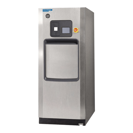
- Page 1 OPERATOR MANUAL AMSCO ® 400 Series Small Steam Sterilizers 16 x 16" (406 x 406mm) 20 x 20" (508 x 508 mm) • Prevacuum • Steam Flush Pressure Pulse (05/22/15) P129394-020 Rev. AB...
- Page 3 STERIS Corporation carries a complete line of accessories for this unit to simplify, organize and assure the conditions for sterilization have been achieved. Instrument trays, pouches and biological/ chemical monitoring systems are all available to fulfill your facility’s...
- Page 4 Factory-Set Cycles and Cycle Values – Prevacuum Sterilizer The AMSCO 400 Series 16 and 20 Small Prevacuum Steam Sterilizer 16 x 16" (406 x 406 mm) and 20 x 20" (508 x 508 mm) is equipped with the following factory programmed sterilization cycles and cycle values...
- Page 5 ® Table 1. AMSCO 400 Series Prevacuum Sterilizer Cycles (Continued) Recommended Load Sterilize Sterilize Validation Cycles: Refer to Table 4 (page vi) for Temp. Time Time Standard Recommended Quantities Immediate Use 270°F 3 Minutes 1 Minute Unwrapped instrument tray containing ST-8:2008 Gravity Cycle (132°C)
- Page 6 Factory-Set Cycles and Cycle Values – Steam Flush Pressure Pulse Sterilizer The AMSCO 400 Series 16S and 20S Small Steam Flush Pressure Pulse (SFPP) Sterilizer 16" x 16" (406 x 406 mm) and 20" x 20" (508 x 508 mm) is equipped with the following factory programmed sterilization cycles and...
- Page 7 Table 2. AMSCO 400 Series SFPP Sterilizer Cycles (Continued) Recommended Load Sterilize Sterilize Validation Cycles: Refer to Table 4 (page vi) for Temp. Time Time Standard Recommended Quantities Gravity Cycle 270°F 15 Minutes 30 Minutes ST-8:2008 Double-wrapped instrument trays. (132°C)
- Page 8 Rack and Shelves * The liquid cycle is for non-patient contact use only. Table 6. Sterilizer Configurations AMSCO 400 Series Small Steam Sterilizers are offered in the following configurations: 16" Configurations 16 x 16 x 26" (406 x 406 x 660 mm) Single Door, Prevacuum 16 x 16 x 26"...
- Page 9 Facility Steam 7000 btu/hr (7385 kilojoules/hr) w/ Generator 8750 btu/hr (9232 kilojoules/hr) Manufactured by: Sales and Service: STERIS Mexico, S. de R.L. de C.V. STERIS Corporation Avenida Avante 790 5960 Heisley Road Parque Industrial Guadalupe Mentor, Ohio 44060 Guadalupe, Nuevo Leon, Mexico 440-354-2600 •...
- Page 10 viii P129394-020 Operator Manual Introduction...
-
Page 11: Table Of Contents
TABLE OF CONTENTS Section Number Description Page Safety Precautions ........................1-1 Symbols and Labels ........................2-1 Installation Verification ......................... 3-1 Installation Checklist ..........................3-1 Service Clearance..........................3-1 Plumbing Services ..........................3-1 Electrical Service ..........................3-2 Sterilizer Final Check ........................... 3-2 Cycle Operation ........................... - Page 12 TABLE OF CONTENTS Section Number Description Page 5.12 Optional Electric Steam Generator ....................5-20 5.13 Daily Generator Flush Cycle ......................5-21 Sterilizer Operation ........................6-1 Before Operating the Sterilizer......................6-1 Preparing Loads for Sterilization Cycles ....................6-4 Guidelines for Placement of Various Loads..................6-4 Unloading the Sterilizer........................
- Page 13 TABLE OF CONTENTS Section Number Description Page Generator Flush Control ........................7-25 7.9.1 Set up Generator Flush When Manual Utilities Control Enabled........... 7-25 7.9.2 Set up Generator Flush when Automatic Utilities Control Enabled ........7-27 7.10 Language ............................7-28 7.11 Machine Number..........................
- Page 14 TABLE OF CONTENTS Section Number Description Page 9.2.12 Too Long In Air Break ......................9-10 9.2.13 Too Long To Unseal Door ..................... 9-10 9.2.14 Generator Drain Open Failure ....................9-11 9.2.15 Generator Drain Close Failure....................9-12 9.2.16 Too Long to Depressurize Generator ..................9-12 Out-of-Cycle Alarms...........................
- Page 15 LIST OF FIGURES Descrption Page Figure 4-1. Vented Closures ..........................4-5 Figure 5-1. AMSCO 400 Series Small Steam Sterilizer ..................5-1 Figure 5-2. Basic Controls..........................5-3 Figure 5-3. Optional Steam Generator Valve Controls (Sterilizer Frame Not Shown for Clarity)......5-4 Figure 5-4. Typical Out-Of-Cycle and In-Cycle Displays...................5-5 Figure 5-5.
- Page 16 LIST OF FIGURES (CONTINUED) Description Page Figure 7-2. Change Cycle Values Procedure, Part 2 of 3..................7-6 Figure 7-3. Change Cycle Values Procedure, Part 3 of 3..................7-7 Figure 7-4. Enter or Change Custom Cycle Names ..................7-8 Figure 7-5. Scheduling Screen for Auto Utility Control Example #1 ..............7-22 Figure 7-6.
- Page 17 LIST OF TABLES Description Page Table 1. AMSCO 400 Series Prevacuum Sterilizer Cycles................. ii Table 2. AMSCO 400 Series SFPP Sterilizer Cycles ..................iv Table 3. Test Cycles............................v Table 4. Maximum Loads by Sterilizer Chamber Size ..................vi Table 5.
- Page 18 P129394-020 Operator Manual List of Figures and Tables...
-
Page 19: Safety Precautions
• Equipment maintenance other than described in the manual (unless by authorized representatives of the STERIS Corporation), shall be at the risk of invalidating the equipment warranty. • To obtain authorized service call: STERIS Corporation... - Page 20 WARNING – BURN HAZARD: When sterilizing liquids, to prevent personal injury or property damage resulting from bursting bottles and hot fluid, you must observe the following procedures: • Use Liquid cycle only; no other cycle is safe for processing liquids. •...
- Page 21 The performance of the sterilizer is validated as a system including components defined by STERIS in the Operator Manual and Service Manual for the sterilizer. Substitution of unauthorized components can potentially lead to personal injury, damage or premature failure of the product and result in a unit configuration that is inconsistent with the validated product.
- Page 22 Actuation at less than 75% of rated pressure can allow debris to contaminate the seat and cause the safety valve to leak. A leaking safety valve must be replaced. Insufficient service clearance will make repairs more difficult and time-consuming. Piping sized too small may cause water hammer, resulting in damage to the sterilizer. After installation, it is mandatory to brace piping at the drain funnel so that it will not move vertically.
-
Page 23: Symbols And Labels
SYMBOLS AND LABELS ® The following symbols appear on AMSCO 400 Series Small Steam Sterilizers and are provided here for reference. Table 2-1. Symbol Definitions Symbol Definition Symbol Definition Serial number of unit Transfer of heat, hot (located on sterilizer’s surface data plate) Protective earth (i.e.,... -
Page 24: Table 2-2. Label Definitions
• Equipment maintenance other than as described in the Manual (unless by authorized Part Number: 055605-145 representatives of the STERIS Corporation), shall be at the risk of invalidating the equipment warranty Purpose: General information, • To obtain authorized service, call:... - Page 25 Purpose: Summarizes sterilizer Le fonctionnement du stérilisateur est validé en tant que système composé des éléments définis par STERIS dans le manuel de l’utilisateur et dans le manuel d’entretien du validation and warranty concerns stérilisateur. Leur remplacement par des éléments non autorisés risque d’entraîner des blessures du personnel, des dommages ou une panne du produit et aboutir à...
- Page 26 Table 2-2. Label Definitions (Continued) Label Definition Part Number: 055605-143 HOT SURFACE HAZARD Purpose: Indicates concerns for hot PELIGRO SUPERFICIE surfaces or burn hazard CALIENTE Location: On front panel (and rear DANGER SURFACE panel when present) CHAUDE See: 6, S ECTION TERILIZER PERATION...
- Page 27 Table 2-2. Label Definitions (Continued) Label Definition Part Number: 055605-152 Purpose: Indicates power door operating control (foot pedal) Location: On control panel, adjacent DOOR - OPEN / CLOSE to foot pedal PUERTA - ABIERTA / CERRADA PORTE - OUVRIR / FERME See: 5.9, P ECTION...
- Page 28 P129394-020 Operator Manual Symbol and Labels...
-
Page 29: Installation Verification
After installing this unit according to the instructions provided, complete the following checklist to assure that your installation is Checklist complete and correct. Or, if you desire, contact STERIS for a technician to be scheduled to test your installation and demonstrate proper equipment operation. -
Page 30: Electrical Service
❑ Steam Supply: ❑ Shutoffs (with provisions for lockout and tagout) located nearby. CAUTION – POSSIBLE ❑ Supply piping adequately sized. EQUIPMENT DAMAGE: After ❑ Supply pressure measured (specification is 50 to 80 psig installation, it is mandatory to [3.5 to 5.52 bar], dynamic). brace piping at the drain funnel so it will not move ❑... -
Page 31: Techniques Of Sterilization
NOTE: Contact STERIS for information on a wide range of education/ training programs designed to meet the educational needs of healthcare industries. -
Page 32: Biological Monitors
® 4.3.1 Biological Monitors Tests such as the Dart (Daily Air Removal Test) or Bowie-Dick are designed to document the removal of residual air from a sample challenge load. Run a Dart (Bowie-Dick test) cycle daily before processing any loads in a sterilizer equipped with prevacuum cycles. -
Page 33: Vacuum Leak Test
4.5 Vacuum Leak Test The Vacuum Leak Test (see appropriate cycle description in 6, S ) measures the integrity of the ECTION TERILIZER PERATION sealed pressure vessel and associated piping to assure air is not being admitted to the sterilizer during the vacuum drawdowns. After running a Leak Test cycle, a value or leak rate will be printed on WARNING –... -
Page 34: Techniques Of Sterilization For Liquid Cycle
4.7 Techniques of Sterilization for Liquid Cycle WARNING – EXPLOSION HAZARD: This sterilizer is not designed to process flammable compounds. WARNING – PERSONAL INJURY HAZARD: Avoid personal injury from bursting bottles. Liquid sterilization cycle must only be used for liquids in borosilicate (Pyrex) flasks with vented closures. WARNING: The liquid cycle is for non-patient contact use only. -
Page 35: Recommendations For Sterilizing Liquids
4.8 Recommendations Important: Read the following paragraphs before sterilizing any liquids in your sterilizer. The liquid cycle is for non-patient contact for Sterilizing Liquids use only. WARNING – EXPLOSION Containers of liquid must be located at least 4" (102 mm) from the HAZARD: The liquid cycle is sterilizer chamber door(s). -
Page 36: Sterilization Of Implantable Devices
4.9 Sterilization of A healthcare facility must develop adequate monitoring practices for sterilization implantable devices. Refer AORN Implantable Devices recommended practices for more information. Sterilization of implantable devices by a healthcare facility must be monitored: • When sterilizing an implantable device, always place a biological monitor in the load. -
Page 37: Component Identification
COMPONENT IDENTIFICATION Cycle Printout Touch Screen and Printer Emergency Stop Switch Main Control Enclosure (Above chamber, behind front access panel) Access Panel (Front panel of sterilizer is hinged for service access) Chamber Rack and Shelves Foot Pedal JAC KET CHAMBER Generator Water Supply Main Power Valve... -
Page 38: General
5.1 General Use this manual to become familiar with control locations and functions before operating the sterilizer (refer to Figures 5-1 or 5-2). The controls for this sterilizer are contained within the control touch screen. Control touchpads appear on the screen as needed during each operation. -
Page 39: Figure 5-2. Basic Controls
Steam Supply Valve STATUS . . STANDBY TIME . . . 10:20:00 AM DATE . . . 2/20/94 Standby Screen Water Supply Valve Figure 5-2. Basic Controls NOTE: Touch-screen pads respond to very slight pressure, and only need to be pressed lightly. The sterilizer enters operating mode when the ON touchpad is pressed. -
Page 40: Figure 5-3. Optional Steam Generator Valve Controls (Sterilizer Frame Not Shown For Clarity)
Yellow Ball Valve – Pressure Gauge Control (Do Not Adjust) Yellow Ball Valves – Hot Water Supply Sight Glass Generator Drain Manual Valve Blue Gate Valve – Hot Water Supply Figure 5-3. Optional Steam Generator Valve Controls (Sterilizer Frame Not Shown for Clarity) P129394-020 Operator Manual Component Identification... -
Page 41: Control Displays
5.3 Control Control displays can be divided into two categories, those occurring when the sterilizer is “out-of-cycle” and those occurring when the Displays sterilizer is “in-cycle.” Typical out-of-cycle and in-cycle displays are shown in Figure 5-4: • Out-of-cycle displays are used to start cycles, or set up and adjust sterilizer operation. -
Page 42: Alarm Displays
5.4 Alarm Displays Alarm displays tell operators and technicians when the sterilizer is experiencing an abnormal condition. Alarm conditions can be caused by failure of utility supplies or sterilizer components. 9, T details the steps an operator can take ECTION ROUBLESHOOTING to solve most alarm conditions. -
Page 43: Operating End Control Panel
5.5 Operating End A sterilizer equipped with two doors will also be equipped with two control panels. The control panel at the loading door of the sterilizer Control Panel is referred to as the “operating end control” (OE control); the control panel located at the unloading door is referred to as the “non- operating end control”... -
Page 44: Figure 5-6. Control Panels
Emergency Stop Cycle Printout Touch Screen Button Typical Menu Screen Operating End Control Panel Typical In-Cycle Screen Non-Operating End Control Panel Figure 5-6. Control Panels P129394-020 Operator Manual Component Identification... -
Page 45: Cycle Selection Touch-Screen Pads
6, S ECTION TERILIZER PERATION The AMSCO 400 Series Steam Sterilizer control can be programmed to retain values for up to 12 separate cycles. User-defined cycle names can be entered for cycles 1 and 2 on the cycle selection screen. -
Page 46: Figure 5-7. Cycle Selection Touchpads
® Dart (Bowie-Dick) and Leak Test cycle parameters are fixed; the buttons for these cycles do not display values for exposure temperature, exposure time or drying time. STATUS . . DOOR CLOSED TEMP . . . 128.0 F PRESS . . . 0 PSIG PRESS "MORE CYCLES"... -
Page 47: Values Touch-Screen Pads
5.6.1 Values Touch-Screen The values touch-screen pads are accessed through the MENU Pads screen by pressing CHANGE CYCLE VALUES (refer to Figure 5-8). These pads are used for changing the operating values used in cycles, changing the cycles displayed on the cycle selection menus and for changing the operating settings of the sterilizer. -
Page 48: Abort Touch-Screen Pad
5.6.2 Abort Touch-Screen The Abort touch-screen pad is used to end a cycle before it finishes normally. A cycle only needs to be aborted if an abnormal condition or a control problem develops during the cycle. Pressing Abort causes the sterilizer chamber to depressurize (if pressurized), or Air Break (if in vacuum);... -
Page 49: Printer
5.7 Printer Refer to Figure 5-10 Printer records all cycle data on 2-1/4" (57 mm) wide single-ply paper. See 8.4.1, C ECTION HECK RINTER APER OLL ON PAGE paper changing procedure. Printer functions controlled by touch- screen pads are as follows: •... -
Page 50: Printouts
5.8 Printouts Refer to Figure 5-11 The printout reports useful information about each cycle the sterilizer runs. The sterilizer control assigns an automatically created load number that appears on the cycle printout. The load number is a unique identifying code. The coded load number prints in the following format: •... -
Page 51: Figure 5-11. Typical Printout
Cycle Type Cycle Start Time & Date Cycle Count Total Operator I.D. Machine Number & Serial Number Sterilize Temperature Control Overdrive Temperature Sterilize Time Dry Time Status Print Codes: Additional Status Print Codes: Conditioning F = Alarm (Failure) Charge L = Leak Test (Vacuum or Hold) Vacuum Pulses D = Demand Print (Print Status) Sterilize... -
Page 52: Power-Door Operation
5.9 Power-Door The sterilizer door is operated at the foot pedal (refer to Figure 5-12). Operation • Pressing the foot pedal while the door is in the closed (up) position causes the door to open (lower). • Pressing the foot pedal while the door is in the open (lowered) position, causes the door to close (by raising). -
Page 53: Emergency Door Opening Procedure
5.10 Emergency Door This procedure should only be used when pressure remains in the sterilizer chamber, and the door cannot be opened normally Opening Procedure because the sterilizer has lost either electrical or water utilities. • Use emergency door opening procedure to retrieve a load WARNING –... -
Page 54: Emergency Stop Switch
5.11 Emergency Stop An emergency stop switch (Figure 5-14) is a safety feature designed to shut the sterilizer down completely in an emergency situation. Switch Pressing the emergency stop switch disconnects power to the door and valves, causing the door to stop and most valves to close, except S1 and S40, which are normally open, and will open when the emergency stop switch is pressed. -
Page 55: Emergency Stop Key
The emergency stop switch should be pressed only in an emergency situation such as • Safety mechanism fails to stop door when an obstruction is present • Steam enters the chamber when the door is open NOTE: An alarm is generated when the emergency stop switch is pressed. -
Page 56: Optional Electric Steam Generator
(38.5 micro-ohms, conductivity min.). Do not connect to treated water (e.g., distilled, reverse osmosis, deionized) unless water resistivity is determined to be Ω · acceptable. If water exceeds 26,000 cm, contact STERIS Service Engineering for information concerning modifications required to the generator control system. 5-20 P129394-020... -
Page 57: Daily Generator Flush Cycle
5.13 Daily Generator The generator flush cycle is automatic and occurs as scheduled by the sterilizer operator using the procedure in 7.8, U Flush Cycle ECTION TILITIES 7-17. ONTROL ON PAGE • If auto-utilities is enabled, the sterilizer initiates a daily flush of the generator’s boiler one hour before utilities have been scheduled to turn on. -
Page 58: Figure 5-17. Integral Generator Flush Cycle
212°F Jacket Temperature Generator Pressure 0 psig Figure 5-17. Integral Generator Flush Cycle Alarm intervals (such as “Too Long to Depressurize Generator”) must be adjusted by trained technicians, only. Contact STERIS for this service. 5-22 P129394-020 Operator Manual Component Identification... - Page 59 STATUS . .FLUSH 0:00 TEMP . . .00 F PRESS . . .00 inHg GENERATOR FLUSH PROJECTED CYCLE COMPLETION TIME: 05:00 MINUTES SECONDS PAPER STATUS ABORT FEED PRINT 4. Complete – The automated generator drain ball valve closes at end of flush. •...
- Page 60 5-24 P129394-020 Operator Manual Component Identification...
-
Page 61: Sterilizer Operation
STERILIZER OPERATION 6.1 Before Operating Operate sterilizer by referring to the appropriate cycle description in this section. The information in through the Sterilizer ECTION ECTION general instructions that apply to all cycle operations. 1. Press ON touch-screen pad on the sterilizer control display. WARNING –... -
Page 62: Figure 6-1. Utility Supply Valves And Basic Sterilizer Controls
STATUS . . STANDBY TIME . . . 10:20:00 AM DATE . . . 2/20/2011 Touch ON button to Advance to Cycle Selection Screen Steam Supply Valve Standby Screen STATUS . .DOOR CLOSED TEMP . . .128 F PRESS . . .0 PSIG PRESS "MORE CYCLES"... -
Page 63: Figure 6-2. Optional Steam Generator Check List
Steam Generator Check List – if optional steam generator is present: Open Sterilizer Check Pressure Front Access 1. Open front access panel. Gauge Panel 2. Check generator pressure gauge. If pressure shown, proceed to Step 6. 3. Check yellow handle ball valve near pressure gauge. -
Page 64: Preparing Loads For Sterilization Cycles
6.2 Preparing Loads Before sterilization, all materials must be thoroughly cleaned. for Sterilization Cycles ® The AMSCO 400 Series small steam sterilizer chamber holds commonly used wrapped or unwrapped instruments and equipment. 1. Wrappers may be made of 100% cotton, 140 thread count, two- ply fabric, and must be laundered;... -
Page 65: Unloading The Sterilizer
6.4 Unloading the At the end of a cycle, when end-of-cycle tone sounds and display shows the complete screen (see below), open the chamber door: Sterilizer WARNING – BURN HAZARD: STATUS . .COMPLETE 00:00:00 • Sterilizer and shelves will be TEMP . -
Page 66: Loading Car Instructions: Loading
6.5 Loading Car NOTE: The loading car and transfer carriage are for use with the 20-inch Instructions: AMSCO 400 Series sterilizer, only. Loading 1. Open sterilizer door. WARNING – BURN HAZARD: 2. Verify that loading car is securely fastened to the transfer Reduce risk of liquid boil-over. -
Page 67: Loading Car Instructions: Unloading
6.6 Loading Car NOTE: The loading car and transfer carriage are for use with the 20-inch Instructions: AMSCO 400 Series sterilizer, only. Unloading 1. Open sterilizer door. 2. Move transfer carriage forward until latches engage with track WARNING – BURN HAZARD: inside chamber. -
Page 68: Prevacuum Sterilizer Cycles
Figure 6-4. Sterilizer Chamber Equipped with Rack and Shelves 6.8 Prevacuum AMSCO 400 Series Steam Prevacuum Sterilizers are shipped with the factory-set cycles. Cycle descriptions are given in 6.9, Sterilizer Cycles ECTION through 6.14. - Page 69 Sterilizer Operation Operator Manual P129394-020...
-
Page 70: Table 6-1. Factory-Set Prevacuum Cycles And Cycle Values
Table 6-1. Factory-Set Prevacuum Cycles and Cycle Values The AMSCO 400 Series Prevacuum Sterilizer is equipped with the following factory programmed prevacuum sterilization cycles and cycle values. Sterilize Sterilize Validation Cycles Temp. Time Time Recommended Load Standard 270°F Prevac Cycle... -
Page 71: Prevac Cycles
6.9 Prevac Cycles Prevac cycles, 270°F (132°C), are used for sterilizing double- wrapped instrument trays or fabric packs. Prevac cycles, 275°F (135°C), are used for sterilizing double-wrapped instrument trays only. Immediate use cycles must not be used with wrapped loads or fabrics. -
Page 72: Figure 6-6. Typical Prevacuum Cycle Printouts
270°F (132°C) Prevac, 270°F (132°C) Prevac, Full Load, Fabric Packs Immediate Use Cycle Printout Cycle Printout Figure 6-6. Typical Prevacuum Cycle Printouts 6-12 P129394-020 Operator Manual Sterilizer Operation... - Page 73 6-13 Sterilizer Operation Operator Manual P129394-020...
-
Page 74: Table 6-2. Factory-Set Gravity Cycles And Cycle Values
Table 6-2. Factory-Set Gravity Cycles and Cycle Values The AMSCO 400 Series Prevacuum Sterilizer is equipped with the following factory programmed gravity sterilization cycles and cycle values. Sterilize Sterilize Validation Cycles Temp. Time Time Recommended Load Standard Immediate Use Gravity 270°F... -
Page 75: Gravity Cycles
6.10 Gravity Cycles The Gravity cycle is used for sterilizing one or more unwrapped instrument trays containing non-porous items. WARNING – BURN HAZARD: 1. Refer to 6.1, B ECTION EFORE PERATING THE TERILIZER before running this cycle. • Sterilizer, rack/shelves and PAGE loading equipment will be hot 2. -
Page 76: Figure 6-8. Typical Gravity Cycle Printout
270°F (132°C) Gravity, Immediate Use Cycle Printout Figure 6-8. Typical Gravity Cycle Printout 6-16 P129394-020 Operator Manual Sterilizer Operation... - Page 77 6-17 Sterilizer Operation Operator Manual P129394-020...
-
Page 78: Table 6-3. Factory-Set Optional Liquid Cycle And Cycle Values
Table 6-3. Factory-Set Optional Liquid Cycle and Cycle Values The AMSCO 400 Series Sterilizer is equipped with the following optional factory programmed liquid sterilization cycle and cycle values. Sterilize Recommended Load Validation Cycles Sterilize Temp. Time Time (by Chamber Size) Standard 16 x 16"... -
Page 79: Liquid Cycle
6.11 Liquid Cycle This cycle is used for sterilizing liquids in vented closures. 1. Refer to 6.1, B ECTION EFORE PERATING THE TERILIZER WARNING – EXPLOSION before running this cycle. PAGE HAZARD: This sterilizer is not 2. See instructions for using the loading car/transfer carriage or designed to process flammable compounds. -
Page 80: Figure 6-10. Typical Printout Of A Liquid Cycle
Figure 6-10. Typical Printout of a Liquid Cycle 6-20 P129394-020 Operator Manual Sterilizer Operation... -
Page 81: Sfpp Sterilizer Cycles
6.12 SFPP Sterilizer AMSCO 400 Series SFPP Steam Sterilizers are shipped with the factory-set cycles. The cycle sequence for these cycles is given in Cycles 6.13 (prevac and gravity cycles are described in ECTION ECTION 6.9, 6.10 6.11). Refer below, and to... -
Page 82: Table 6-4. Factory-Set Sfpp Sterilizer Cycles And Cycle Values
Table 6-4. Factory-Set SFPP Sterilizer Cycles and Cycle Values Sterilize Sterilize Validation Cycles Temp. Time Time Recommended Load Standard Double-wrapped instrument trays, porous and non- 270°F SFPP Cycle porous loads. Maximum ST-8:2008 (132°C) Minutes Minutes weight per tray, 25 lb (11.3 kg) 270°F SFPP Cycle... -
Page 83: Sfpp Cycles
6.13 SFPP Cycles SFPP cycles are designed for sterilizing both fabric packs and instrument trays. The cycle conditions loads at above-atmospheric pressure. WARNING – BURN HAZARD: NOTE: NOTE: Make sure items are clean and free of soil. • Sterilizer, rack/shelves, and loading car will be hot after 1. -
Page 84: Figure 6-12. Typical Printouts - 270°F Sfpp And 275°F Sfpp Cycles
275°F (135°C) SFPP, 270°F (132°C) SFPP, Full Load, Instruments Trays Full Load, Fabric Packs Cycle Printout Cycle Printout Figure 6-12. Typical Printouts – 270°F SFPP and 275°F SFPP Cycles 6-24 P129394-020 Operator Manual Sterilizer Operation... -
Page 85: Test Cycles
6.14 Test Cycles Test cycles are factory programmed on prevacuum sterilizers. These cycles are used to verify the sterilizer is functioning at optimum capability. Table 6-5. Test Cycles Test Cycles for Sterilize Validation All Units Temp. Sterilize Time Time Recommended Load Standard 270°F (132°C) 3 Minutes... -
Page 86: Daily Air Removal (Bowie-Dick) Test Cycle
6.14.1 Daily Air Removal This cycle is used to conduct a Bowie-Dick test (or “air-removal” test) (Bowie-Dick) Test Cycle on sterilizers that use prevacuum cycles. This test is only applicable to sterilizers that use prevacuum cycles. For SFPP sterilizers, if the SFPP cycle is used exclusively, there is no need to run a daily air- removal test. - Page 87 STERILIZE – Start of sterilize exposure is printed when the chamber reaches set temperature. Chamber temperature is printed every minute. Chamber is controlled at set point plus overdrive. FAST EXHAUST – Start of exhaust is printed and chamber is WARNING – BURN HAZARD: exhausted to 4 psig (0.28 bar).
-
Page 88: Figure 6-14. Daily Air Removal (Bowie-Dick) Test Cycle Printout
Daily Air Removal Test (Dart) Cycle Printout Figure 6-14. Daily Air Removal (Bowie-Dick) Test Cycle Printout 6-28 P129394-020 Operator Manual Sterilizer Operation... -
Page 89: Vacuum Leak Test
6.14.2 Vacuum Leak Test This cycle is used for testing vacuum integrity of the sterilizer and piping. A Vacuum Leak Test cycle should be run on the sterilizer at least WARNING – BURN HAZARD: once each week. It should be one of the first cycles run for the day, •... -
Page 90: Figure 6-15. Typical Printout Of A Leak Test Cycle
Leak Test Cycle Printout Figure 6-15. Typical Printout of a Leak Test Cycle 6-30 P129394-020 Operator Manual Sterilizer Operation... -
Page 91: Aborting Cycles
6.15 Aborting Cycles It may be necessary to end a processing cycle, possibly because the wrong cycle was selected or the sterilizer begins functioning incorrectly. A cycle can be aborted at any time by pressing the ABORT touch-screen pad. 1. Touch the ABORT touch-screen pad. WARNING –... -
Page 92: Cycle Graphs
6.16 Cycle Graphs These cycle graphs provide a visual representation of AMSCO 400 Series Steam Sterilizer cycles and their phases. Conditioning Sterilize Exhaust Fast Pulses Purge Charge Indicates Key Cycle Transition Points That Are Printed During Cycle Time * NOTE: 270°F (132°C) prevac cycle runs four conditioning vacuum pulses. 275°F (135°C) prevac runs three conditioning vacuum pulses. -
Page 93: Figure 6-17. Cycle Graph - Gravity Cycle
Conditioning Sterilize Exhaust Fast Exh Vac Dry Purge Charge Vacuum Dry phase only occurs when Dry Time Indicates Key Cycle is set to 0. Transition Points That Are Printed During Cycle Time Figure 6-17. Cycle Graph – Gravity Cycle Leak Testing Conditioning Pulse Pulse... -
Page 94: Figure 6-19. Cycle Graph - Steam Flush Pressure Pulse (Sfpp) Cycles
Conditioning Sterilize Exhaust 3 Pulses & Steam Flushes Exhaust Flush Pulse Exhaust Flush Indicates Key Cycle Transition Points That Are Printed During Cycle Time Figure 6-19. Cycle Graph – Steam Flush Pressure Pulse (SFPP) Cycles Conditioning Sterilize Slow Exhaust Purge Charge Indicates Key Cycle Transition Points That... -
Page 95: Cycle And Control Value Programming
NOTE: Although AMSCO 400 Series Steam Sterilizers are factory- set to operate using Fahrenheit temperature units, the sterilizer can be reprogrammed to display and print using Celsius temperature units. -
Page 96: Change Cycle Values
7.2 Change Cycle Refer to Figures 7-1 through 7-3. Values 7.2.1 Overview 1. Press the ON touch screen pad, if the sterilizer is in STANDBY. The control advances to Status screen #1. 2. At screen #1, press the MENU touch screen pad, and the control advances to screen #2;... - Page 97 NAME TEMP STER SELECT NEW CYCLE NAME OR SELECT ANOTHER ITEM TO CHANGE PREVAC GRAVITY LIQUID SFPP NONE EXIT Cycle values (sterilize temperature and time, and dry time) are adjustable within the limits shown in Table 7-1. TEMP: For changing sterilize exposure temperature within the •...
-
Page 98: Table 7-1. Adjustment Ranges For Cycle Values
Table 7-1. Adjustment Ranges for Cycle Values Cycle Type Sterilize Time Dry Time Sterilize Temperature 270°F (132°C) Prevac 4 - 99 minutes 270 - 274°F (132 - 134°C) 1 - 99 minutes 275°F (135°C) Prevac 3 - 99 minutes 275°F (135°C) 270°F (132°C) SFPP 4 - 99 minutes 270 - 274°F (132 - 134°C) -
Page 99: Step By Step Flowchart
7.2.3 Step by Step Flowchart IMPORTANT: Applicable cycles have been validated to satisfy the requirements outlined in Table 1 Table 2. If cycle parameters (sterilize time, dry time, temperature) other than those listed are required, it is the responsibility of the healthcare facility to consult and follow the device manufacturer’s written... - Page 100 7-2, below, is a continuation of the flow chart in 7-1. IGURE IGURE Comments: Important: Pressing EXIT causes the sterilizer to leave Change Values, saving any changes made to the point where EXIT was pressed. A printout of cycle values and the cycle count is provided by pressing PRINT...
- Page 101 Comments: Select Value • Press NAME touchpad to change cycle type • Press TEMP touchpad change sterilization exposure temperature. • Press STER touchpad to change Sterilization Exposure Time • Press DRY touchpad to change Drying Time TEMP, STER or DRY values can be entered or changed using the numeric touchpads.
-
Page 102: Entering Custom Cycle Names
7.3 Entering Custom Cycle Names EXAMPLE: CUSTOM NAMES are used to add descriptive text to the cycle selection buttons. • CLEAR button erases all text entered. • <- and -> buttons move the cursor position left or right. Figure 7-4. Enter or Change Custom Cycle Names P129394-020 Operator Manual Cycle and Control Value Programming... - Page 103 7.4 Change Time and Set time and date the sterilizer uses for all display and printout messages. Refer to 7.7, L 7-15 Date ECTION OCKOUT ON PAGE instructions on locking the time and date change feature. The current time and date appears on the Off/Standby (screen #0) and Status (screen #1) screens.
- Page 104 b. If an incorrect number is entered, press TIME to start over, or use the cursor arrows at the bottom of the screen to back up to an incorrect number. TIME DATE ENTER TIME OR SELECT "DATE" TO SET ENTER TIME OR SELECT "DATE" TO SET TIME = 00:00 TIME = 00:00 EXIT...
- Page 105 b. If an incorrect number is entered, press DATE again to start over, or use the cursor key pads at the bottom of the screen to backup to an incorrect number. TIME DATE ENTER TIME OR SELECT "DATE" TO SET ENTER TIME OR SELECT "DATE"...
-
Page 106: Change Machine Setup
7.5 Change Machine All changes are made to displayed settings using touch screens. No mechanical adjustments to the sterilizer are necessary. Setup Generally, the Setup options are used to change the way the sterilizer operates. The control has an Access Code Security feature. If the Access Code is enabled, all or some of these options can be secured or “locked out”... -
Page 107: Access Code
7.6 Access Code This setup option is used to control access to the adjustment functions of the sterilizer control. • When the Access Code is ON, a four-digit code must be entered before changing any locked-out functions. • Functions are selected for lock out by supervisor or operator. 7.6.1 Enabling or Disabling 1. - Page 108 SELECT GENERAL ACCESS CODE OPTION SELECT CODE REQUIRED TO SET CODE VALUE CODE CODE REQUIRED EXIT REQUIRED • CODE REQUIRED. Press CODE REQUIRED touchpad. The display advances to screen #35. This screen prompts for the entry of a four-digit code. a.
-
Page 109: Entering The Access Code, Once Enabled
4. If the Access Code is already enabled and ACCESS CODE touchpad is pressed at the Change Machine Setup screen (#20), the display advances to screen #37 and the control prompts the user to enter the Access Code. a. Enter Code using the touchpads at the right of the screen. b. - Page 110 2. Press LOCKOUT touchpad on the Setup menu screen (#20). The display changes to show the Enter Access Code screen (#37). SELECT MACHINE SETUP TO REVIEW OR CHANGE LOCKOUT ACCESS UTILITIES LANGUAGE CODE CONTROL MACHINE TIME PRINT AUDIBLE NUMBER FORMAT FORMAT SIGNALS UNITS...
-
Page 111: Utilities Control
a. Press the touchpad(s) for the cycles you want to lock out. The lock graphic in the corner of the pad changes to reflect the lockout status. SELECT CYCLE TO LOCKOUT PREVAC PREVAC PREVAC PREVAC 273F 273F 273F 273F PREVAC PREVAC PREVAC PREVAC... -
Page 112: Manual Utilities Control
3. Press UTILITIES CONTROL and screen advances to Utilities Control screen (#39). SELECT UTILITIES CONTROL OPTION SELECT AUTOMATIC TO SET AUTOMATIC TIMES SELECT GENERATOR FLUSH CONTROL TO SET GENERATOR FLUSH AND DURATION TIMES SELECT RUN GENERATOR FLUSH TO FLUSH THE GENERATOR SELECT FLUSH HISTORY TO VIEW AND PRINT GENERATOR FLUSH HISTORY GENERATOR... - Page 113 3. Press EXIT to return to Menu (#2). 4. Press EXIT once more to update flash memory and return to main screen (#1). » Standby Screen (#0): Operator selects STANDBY from main screen (#1) to turn off utilities. Power must still be supplied to the sterilizer controls. Operator selects ON from the standby screen to restart utilities.
-
Page 114: Automatic Utilities Control
• Start up and shut off times for all week days. • Start up and shut off times for weekend days. SELECT UTILITIES CONTROL OPTION SELECT AUTOMATIC TO SET AUTOMATIC TIMES SELECT GENERATOR FLUSH CONTROL TO SET GENERATOR FLUSH AND DURATION TIMES SELECT RUN GENERATOR FLUSH TO FLUSH THE GENERATOR SELECT FLUSH HISTORY TO VIEW AND PRINT... - Page 115 » Generator Flush and Drain with Automatic Utilities Control: Sterilizers equipped with optional integral steam generators automatically flush the generator one hour prior to scheduled utilities restart time while in auto utilities shutdown mode. Flush cycle duration can be specified using GENERATOR FLUSH CONTROL screen (#49).
-
Page 116: Figure 7-5. Scheduling Screen For Auto Utility Control Example #1
24-HR NOTE: If time is selected (see 7.12, T ECTION 7-29), AM and PM touchpads are not displayed ORMAT ON PAGE and screen #33 is replaced by screen #44. 4. Once start up and shut off times are scheduled, press EXIT. Display returns to Utilities Control. -
Page 117: Figure 7-6. Scheduling Screen For Auto Utility Control Example #2
13. Review schedule. 14. Edit if needed. 15. Press EXIT when done. Utilities control is now programmed to turn sterilizer’s utilities on at 7:00 AM and off at 6:30 PM Monday through Friday. Saturday, utilities turn on at 6:00 AM and off at 12:00 PM. Utilities are off all day Sunday. -
Page 118: Figure 7-7. Scheduling Screen For Auto Utility Control Example #3
12. Press EXIT. 13. At screen #34, press WEEKEND touchpad. 14. At screen #33, press NONE. 15. Review schedule. 16. Edit if needed. 17. Press EXIT when done. NOTE: On days equipment runs continuously on consecutive days, restart time needs to be set to 12:00 AM, or equipment automatically shuts down at 12:00 AM. -
Page 119: Generator Flush Control
7.9 Generator Flush If the sterilizer is equipped with an integral steam generator, GENERATOR FLUSH CONTROL set up consists of two options: Control FLUSH TIME (#48) and FLUSH DURATION (#49). • Flush duration applies when utilities are being controlled automatically or manually. •... -
Page 120: Figure 7-9. Generator Flush Time And Duration Screens When Manual Utilities Enabled
Figure 7-9. Generator Flush Time and Duration Screens when Manual Utilities Enabled 2. Select FLUSH TIME and schedule time of day for generator to begin daily flush. Use keypad to enter time (four digits), then press AM or PM. 3. Select FLUSH DURATION. Use keypad to enter duration of flush phase (5, 10 or 15 minutes). -
Page 121: Set Up Generator Flush When Automatic Utilities Control Enabled
7.9.2 Set up Generator Flush Auto utility control must be highlighted on utility control screen (#39). when Automatic Utilities Important: Sterilizer must be in auto utility shutdown screen (#40) Control Enabled for flush to occur. Flush cycle will not occur if sterilizer is at STANDBY screen (#0) at scheduled time. -
Page 122: Language
7.10 Language AMSCO 400 Series sterilizer is capable of operation with display screens and printouts in two of three languages. The factory default is ENGLISH. A BILINGUAL option can be used to easily change languages between shifts or whenever necessary. -
Page 123: Machine Number
7.11 Machine Number This set up is used to enter an identifying, two-character code into the sterilizer control. This code can be letters, numbers or a combination of both. The Machine Number code is printed out in the header for each cycle, allowing for processed goods to be traced back to a specific sterilizer when needed. -
Page 124: Print Format
SELECT TIME FORMAT AM/PM 24 HOUR EXIT 3. Select the appropriate time format by pressing one of the two touchpads in the lower half of the display. • AM / PM – This is the standard civilian time format. • 24 HOUR –... - Page 125 SELECT PRINT FORMAT FULL CONDENSED EXIT 3. Select the appropriate print format by pressing one of the two touchpads in the lower half of the display. • FULL – This is the standard format providing a status print for each phase of the cycle and status prints at the predetermined Print Interval.
-
Page 126: Figure 7-11. Sample Full And Condensed Printouts
Condensed Printout (Typical) Full Printout (Typical) Figure 7-11. Sample Full and Condensed Printouts 7-32 P129394-020 Operator Manual Cycle and Control Value Programming... -
Page 127: Audible Signals
7.14 Audible Signals This setup option allows the operator to adjust selected audible signals heard at the sterilizer control. Three signals can be adjusted. Touchpad and end of cycle signals can be adjusted to one of three volume levels or turned off. Only the volume level of the Alarm signal can be adjusted. -
Page 128: Units
7.15 Units This feature is used to select or change the units the sterilizer uses when displaying and printing chamber temperature and pressure. This function allows selection of either Fahrenheit or Celsius units for displaying and printing temperature. Pressure units can be changed between psig/inHg, mbar or psia. -
Page 129: Duplicate Print
SELECT DATE FORMAT = DAY = MONTH = 3 LETTER ABBREVIATION FOR MONTH = YEAR M-D-Y D-M-Y Y-M-D EXIT MON-D-Y D-MON-Y Y-MON-D • Y-M-D – Year-Month-Day • MON-D-Y – Month-Day-Year* • D-MON-Y – Day-Month-Year* • Y-MON-D – Year-Month-Day* * When selecting the format touchpads in the bottom row, MON = 3 letter abbreviation of the month. -
Page 130: Leaving Change Values
SELECT AUTOMATIC DUPLICATE PRINT STATUS DUPLICATE PRINT DUPLICATE EXIT PRINT c. At screen #27, select the appropriate print option by pressing one of the touchpads on the display. • DUPLICATE PRINT – The sterilizer provides a second printout of the last previous cycle after the cycle completes. -
Page 131: Routine Maintenance
Contact your STERIS Service Representative to schedule preventive maintenance. • The performance of the sterilizer is validated as a system including components defined by STERIS in the Operator Manual and Service Manual for the sterilizer. Substitution of unauthorized components can potentially lead to personal injury, damage or premature failure of the product and result in a unit configuration that is inconsistent with the validated product. -
Page 132: Daily Maintenance Procedures: Clean Chamber Drain Strainer
8.2 Daily Maintenance Recommended Frequency: Clean the drain strainer each day the Procedures: Clean sterilizer is used. Chamber Drain Strainer Important: The chamber drain strainer must be cleaned at least once a day, preferably before running the first cycle. 1. Remove the drain strainer from the drain in the bottom of the WARNING –... -
Page 133: Routine Maintenance Procedure
8.3 Routine Full information for chamber cleaning can be found in STERIS Technical Bulletin, M2826. Maintenance Procedure 8.3.1 Flush Chamber Drain Recommended Frequency: Flush chamber drain whenever the line becomes clogged: 1. Turn off steam supply valve. Wait until jacket pressure is zero. - Page 134 Professional cleaning of the chamber on a yearly basis (or as the operator must turn the local conditions require) is suggested to maintain appearance control power OFF then ON of the chamber interior. Contact STERIS for information to clear the alarm. The regarding this service. control power switch is...
-
Page 135: Printer Maintenance
8.4 Printer Recommended Frequency: Inspect printer every day and perform maintenance as needed. Maintenance Materials Required: • Paper Roll (P93914-204) • Printer Ribbon (P150828-440) 8.4.1 Check Printer Paper Recommended Frequency: Inspect printer paper roll every day. Roll The printer paper roll should be changed whenever colored stripe is visible on one or both edges of printout paper. -
Page 136: Figure 8-3. Printer Components (Printer Door Open)
Take-Up Spool Inner Printer Door Paper Feed Button Printer Door Figure 8-3. Printer Components (Printer Door Open) 2. Tear paper between take-up spool and printer. Refer to Figure 8-4. Figure 8-4. Tear Printer Paper 3. Remove take-up spool from drive by inserting fingers in cavity and lifting slightly to pull spool out. -
Page 137: Figure 8-5. Insert New Paper Roll
6. Insert new paper roll. Refer to Figure 8-5. Figure 8-5. Insert New Paper Roll 7. Insert end of paper into printer roller mechanism just behind ink cartridge. Feed Paper Into Roller Mechanism Figure 8-6. Insert Paper Behind Printer Ink Cartridge Routine Maintenance Operator Manual P129394-020... -
Page 138: Figure 8-7. Press Paper Feed Button To Advance Paper
8. Press paper feed button on printer until paper advances through printer mechanism and ink cartridge, exiting through front. Advance Paper by Pressing Paper Feed Button Figure 8-7. Press Paper Feed Button to Advance Paper 9. Continue pressing paper feed button (or pull paper gently) until about 18”... -
Page 139: Check Printer Ink Cartridge
8.4.2 Check Printer Ink Recommended Frequency: Check printout each day looking for Cartridge any fading in print density. The printer ink cartridge should be changed as soon as type on printouts is light or faded, and before printouts become difficult to read. -
Page 140: Waste Products Disposal
Contact your sales representative for recommendations on cleaning products, biological indicators or parts not listed in Table 8-2. NOTE: Use only STERIS authorized parts on this equipment. Use of unauthorized parts will void the warranty. 8-10 P129394-020 Operator Manual... -
Page 141: Table 8-2. Replacement Parts
Table 8-2. Replacement Parts AMSCO 400 Series Steam Sterilizer 16 x 16" (406 x 406 mm) and 20 x 20” (508 x 508 mm) Schematic Part Schematic Part Designation Number Description Designation Number Description STEAM P146676039 STEAM MANIFOLD (S2, S9, S35) - Page 142 8-12 P129394-020 Operator Manual Routine Maintenance...
-
Page 143: Troubleshooting
Series Steam Sterilizer. If a problem occurs that is not described in this section, please call WARNING – PERSONAL ® STERIS Corporation. A trained service technician will promptly INJURY AND/OR EQUIPMENT place your sterilizer in proper working condition. DAMAGE HAZARD: Repairs and adjustments to this NOTE: Never permit unqualified persons to service the sterilizer. -
Page 144: Typical Alarm Printout
Important: In the event of an alarm condition, the operator should always follow the instructions indicated on the alarm screen. * ALARM ##/##/## PRESSURE IN CHAMBER F 10:07:23A 61.7C 2.34P Full Print Format Shown Figure 9-2. Typical Alarm Printout 9.1.2 Typical Alarm Printout When an alarm occurs the printer automatically generates a printout, typically listing alarm name, time alarm occurred, current chamber status and any associated sensor temperature. -
Page 145: Too Long In Evacuation
Alarm Description Screen with Operator Instructions 9.2.2 Too Long In Occurs if chamber does STATUS . . ALARM! not reach the set Evacuation TOO LONG IN EVACUATION evacuation level within CHAMBER: 00.0 F 0.0 psig the allotted time. STERILIZER WILL: •... -
Page 146: Too Long In Charge
Alarm Description Screen with Operator Instructions 9.2.3 Too Long In Occurs if chamber does STATUS . . ALARM! not reach the set Charge TOO LONG IN CHARGE temperature within the CHAMBER: 00.0 F 0.0 psig allotted time. STERILIZER WILL: • AUTOMATICALLY TRY TO COMPETE CYCLE OPERAT0R INSTRUCTIONS: 1. -
Page 147: Door Unsealed
Alarm Description Screen with Operator Instructions STATUS . . ALARM! 9.2.4 Door Unsealed Occurs if steam DOOR UNSEALED pressure in door seal CHAMBER: 00.0 F 0.0 psig drops below 5 psig. STERILIZER WILL: • AUTOMATICALLY ABORT CYCLE • EXHAUST OR AIR BREAK CHAMBER TO ATMOSPHERIC PRESSURE OPERAT0R INSTRUCTIONS: 1. -
Page 148: Under Sterilize Temperature
Alarm Description Screen with Service Instructions Chamber Pressure/ STATUS . . SERVICE INFORMATION: Temperature Failure PRESSURE/TEMPERATURE FAILURE (Continued) -> PRESSURE OR TEMPERATURE OUTSIDE NORMAL STEAM RANGE CAUSES AND CORRECTIONS: 1. CONTROL OUT OF CALIBRATION -> RECALIBRATE (CONTACT QUALIFIED SERVICE PERSON) 2. -
Page 149: Over Sterilize Temperature
Alarm Description Screen with Operator Instructions STATUS . . ALARM! 9.2.7 Over Sterilize Occurs if chamber OVER STERILIZE TEMPERATURE temperature exceeds Temperature CHAMBER: 00.0 F 0.0 psig the maximum sterilize temperature (Control STERILIZER WILL: temperature + • AUTOMATICALLY CONTINUE CYCLE NOTE: The control over-temperature OPERAT0R INSTRUCTIONS:... -
Page 150: Too Long In Exhaust
Alarm Description Screen with Service Instructions STATUS . . ALARM! 9.2.9 Too Long In Occurs if chamber does TOO LONG IN EXHAUST not exhaust to 4 psig Exhaust CHAMBER: 00.0 F 0.0 psig within the allotted time. STERILIZER WILL: • AUTOMATICALLY TRY TO COMPETE CYCLE •... -
Page 151: Exhaust Rate Too Slow
Alarm Description Screen with Service Instructions Exhaust Rate STATUS . . SERVICE INFORMATION: Too Fast (Continued) EXHAUST RATE TOO FAST -> CHAMBER EXHAUSTED SLOWER THAN THE EXPECTED RATE CAUSES AND CORRECTIONS: 1. SOLENOID VALVE MALFUNCTION -> REPAIR S40 2. SOLENOID VALVE MALFUNCTION ->... -
Page 152: Too Long In Air Break
Alarm Description Screen with Operator Instructions 9.2.12 Too Long In Air Occurs if chamber does STATUS . . ALARM! not air break the Break TOO LONG IN AIR BREAK vacuum to 2 inHg within CHAMBER: 00.0 F 0.0 psig the allotted time. STERILIZER WILL: •... -
Page 153: Generator Drain Open Failure
Alarm Description Screen with Instructions Service Too Long To Unseal STATUS . . SERVICE INFORMATION: Door (Continued) TOO LONG TO UNSEAL DOOR -> DOOR SEAL PRESSURE NOT BELOW 5 PSIG WITHIN ALLOTTED TIME CAUSES AND CORRECTIONS: 1. SEAL PRESSURE SWITCH MALFUNCTION ->... -
Page 154: Generator Drain Close Failure
Alarm Description Screen with Operator Instructions 9.2.15 Generator Occurs if generator STATUS . . ALARM! drain valve will not Drain Close Failure GENERATOR DRAIN CLOSE FAILURE close in one minute. CHAMBER: 00.0 F 0.0 psig STERILIZER WILL: • AUTOMATICALLY ABORT CYCLE OPERAT0R INSTRUCTIONS: 1. - Page 155 Alarm Description Screen with Service Instructions Too Long to STATUS . . SERVICE INFORMATION: Depressurize GENERATOR DEPRESSURIZE FAILURE Generator (Continued) -> GENERATOR DID NOT DEPRESSURIZE WITHIN ALLOTTED TIME CAUSES AND CORRECTIONS: 1. GENERATOR DEPRESSURIZE SWITCH FAILURE -> READJUST GPS SWITCH ->...
-
Page 156: Out-Of-Cycle Alarms
9.3 Out-of-Cycle The following alarm screens will appear only when the sterilizer is not processing a cycle. Alarms Alarm Description Screen with Operator Instructions 9.3.1 Too Long In Occurs if jacket does STATUS . . ALARM! not reach set Jacket Charge TOO LONG IN JACKET CHARGE temperature within CHAMBER:... -
Page 157: Pressure In Chamber
Alarm Description Screen with Operator Instructions 9.3.2 Pressure In Occurs if 2 psig STATUS . . ALARM! Chamber PRESSURE IN CHAMBER pressure is sensed in the chamber. is greater CHAMBER: 00.0 F 0.0 psig than 2 psig, but less STERILIZER WILL: than 50 psig. -
Page 158: Too Long To Close Door
Alarm Description Screen with Service Instructions Atmospheric Pressure STATUS . . SERVICE INFORMATION: Alarm (Continued) ATMOSPHERIC PRESSURE ALARM -> THE ATMOSPHERIC PRESSURE IS GREATER THAN 1 PSI FROM THE CALIBRATED ATMOSPHERIC PRESSURE CAUSES AND CORRECTIONS: 1. THE STERILIZER IS AT A HIGHER ALTITUDE THEN WHERE IT WAS ORIGINALLY CALIBRATED (FACTORY) ->... -
Page 159: Too Long To Open Door
Alarm Description Screen with Operator Instructions 9.3.5 Too Long To Occurs if door switch STATUS . . ALARM! does not open within the Open Door TOO LONG TO OPEN DOOR allotted time. CHAMBER: 00.0 F 0.0 psig STERILIZER WILL: • REMAIN IN ALARM CONDITION UNTIL DOOR IS OPENED OPERAT0R INSTRUCTIONS:... -
Page 160: Control Alarms
9.4 Control Alarms The following alarm screens will appear (under alarm conditions) if the sterilizer is energized. The control is continually monitored whether the sterilizer is in or out of cycle. Alarm Description Screen with Operator Instructions 9.4.1 Input/Output The control board fails STATUS . -
Page 161: Input/Output Board #1 Failure
Alarm Description Screen with Operator Instructions 9.4.2 Input/Output Occurs if switched STATUS . . ALARM! neutral relay circuit Board #1 Failure INPUT/OUTPUT BOARD #1 BOARD FAILURE failed operational contact test on I/O CHAMBER: 00.0 F 0.0 psig board. NOTE: On I/O board #1: STERILIZER WILL: NS1, NS2 or NS3;... -
Page 162: Rom Failure
Alarm Description Screen with Operator Instructions 9.4.4 ROM Failure Occurs if the Read Only STATUS . . ALARM! Memory on the main ROM FAILURE control circuit board CHAMBER: 00.0 F 0.0 psig fails. STERILIZER WILL: • AUTOMATICALLY ABORT CYCLE OPERAT0R INSTRUCTIONS: 1. -
Page 163: Board Overtemp Failure
Alarm Description Screen with Operator Instructions 9.4.7 Board Overtemp Occurs if temperature of STATUS . . ALARM! the main control board Failure BOARD OVERTEMP FAILURE exceeds acceptable CHAMBER: 00.0 F 0.0 psig environmental conditions. STERILIZER WILL: • AUTOMATICALLY ABORT CYCLE OPERAT0R INSTRUCTIONS: 1. -
Page 164: Sensor Alarms
9.5 Sensor Alarms The following alarm screens will appear (under alarm conditions) if the sterilizer is energized. The sensors are continually monitored whenever the sterilizer is in or out of cycle. Alarm Description Screen with Operator Instructions 9.5.1 Water In Occurs if excess water STATUS . -
Page 165: Chamber Temperature Probe Failure
Alarm Description Screen with Operator Instructions 9.5.2 Chamber Occurs if chamber STATUS . . ALARM! temperature reading is Temperature Probe CHAMBER TEMPERATURE PROBE FAILURE outside the normal Failure CHAMBER: 00.0 F 0.0 psig range. STERILIZER WILL: • AUTOMATICALLY ABORT CYCLE OPERAT0R INSTRUCTIONS: 1. -
Page 166: Waste Temperature Probe Failure
Alarm Description Screen with Instructions Service Jacket Temperature STATUS . . SERVICE INFORMATION: Probe Failure JACKET TEMPERATURE PROBE FAILURE (Continued) -> RTD PROBE, JT, OUTPUT IS OUTSIDE NORMAL RANGE CAUSES AND CORRECTIONS: 1. LOOSE CONNECTION IN PROBE WIRING -> REPAIR 2. -
Page 167: Recorder Temperature Probe Failure
Alarm Description Screen with Operator Instructions 9.5.5 Recorder Occurs if output from STATUS . . ALARM! RECORDER recorder temperature Temperature Probe TEMPERATURE PROBE FAILURE probe is outside normal Failure CHAMBER: 00.0 F 0.0 psig range. STERILIZER WILL: • AUTOMATICALLY ABORT CYCLE OPERAT0R INSTRUCTIONS: 1. -
Page 168: Chamber Pressure Transducer Failure
Alarm Description Screen with Operator Instructions 9.5.6 Chamber Occurs if chamber STATUS . . ALARM! pressure reading is Pressure Transducer CHAMBER PRESSURE TRANSDUCER FAIL- outside the normal Failure range. CHAMBER: 00.0 F 0.0 psig STERILIZER WILL: • AUTOMATICALLY ABORT CYCLE OPERAT0R INSTRUCTIONS: 1. -
Page 169: Door Seal A (Or B) Switch Malfunction
Alarm Description Screen with Operator Instructions 9.5.7 Door Seal A (or Occurs if door seal STATUS . . ALARM! switch A (or B) is closed B) Switch Malfunction DOOR A SEAL SWITCH MALFUNCTION out of cycle. CHAMBER: 00.0 F 0.0 psig STERILIZER WILL: •... -
Page 170: Generator Drain Temperature Probe Failure Alarm
Alarm Description Screen with Operator Instructions 9.5.8 Generator Drain Occurs if generator STATUS . . ALARM! GENERATOR DRAIN drain probe Temperature Probe TEMPERATURE PROBE FAILURE temperature is outside Failure Alarm CHAMBER: 70.0 F 0.0 psig normal range: GEN DRAIN: 300.0 RF 32 - 293°F (0 - 145°C). -
Page 171: Generator Drain Switch Failure
Alarm Description Screen with Service Instructions Door Switch Failure (Continued) STATUS . . SERVICE INFORMATION: DOOR SWITCH FAILURE -> DOOR SWITCH OPEN WHILE SEAL SWITCH CLOSED CAUSES AND CORRECTIONS: 1. DOOR SWITCH MALFUNCTION -> CHECK LS1 (LS2) CONNECTIONS -> READJUST LS1 (LS2) ->... -
Page 172: Emergency Stop Switch Pressed
Alarm Description Screen with Operator Instructions 9.5.11 Emergency Occurs if the STATUS . . ALARM! emergency stop switch Stop Switch Pressed EMERGENCY STOP SWITCH PRESSED has been pressed, or CHAMBER: 300.0 F 0.0 psig no ac voltage detected on I/O board. STERILIZER WILL: •... -
Page 173: Generator Pressure Switch Failure
Alarm Description Screen with Operator Instructions 9.5.12 Generator Occurs if generator STATUS . . ALARM! drain pressure switch is Pressure Switch GENERATOR PRESSURE SWITCH FAILURE closed when jacket is Failure CHAMBER: 104.3 F 5.4 psig charged. STERILIZER WILL: • AUTOMATICALLY ABORT CYCLE OPERAT0R INSTRUCTIONS: 1. - Page 174 9-32 P129394-020 Operator Manual Troubleshooting...
Need help?
Do you have a question about the AMSCO 400 Series and is the answer not in the manual?
Questions and answers