Siemens SIRIUS 3RK3 Equipment Manual
Modular safety system
Hide thumbs
Also See for SIRIUS 3RK3:
- System manual (318 pages) ,
- Original operating instructions (21 pages) ,
- Operating instruction (3 pages)
Table of Contents
Advertisement
Quick Links
Industrial Controls
Safety systems
SIRIUS 3RK3 Modular Safety
System
Equipment Manual
07/2020
NEB926253002000/RS-AC/006
About this manual
Product-specific
information
Overview
Getting started with MSS
3RK3 Basic
Description of the hardware
Operation
Diagnostics / service
Technical data
Dimension drawings
1
2
3
4
5
6
7
8
9
Advertisement
Table of Contents

Related Manuals for Siemens SIRIUS 3RK3


Summary of Contents for Siemens SIRIUS 3RK3
- Page 1 About this manual Product-specific information Overview Industrial Controls Getting started with MSS 3RK3 Basic Safety systems SIRIUS 3RK3 Modular Safety Description of the hardware System Operation Equipment Manual Diagnostics / service Technical data Dimension drawings 07/2020 NEB926253002000/RS-AC/006...
- Page 2 Note the following: WARNING Siemens products may only be used for the applications described in the catalog and in the relevant technical documentation. If products and components from other manufacturers are used, these must be recommended or approved by Siemens. Proper transport, storage, installation, assembly, commissioning, operation and maintenance are required to ensure that the products operate safely and without any problems.
-
Page 3: Table Of Contents
Purpose of this manual ...................... 11 Required basic knowledge....................12 Validity range ........................13 Topics dealt with........................ 14 Additional documentation ....................15 Siemens Industry Online Support ..................16 Siemens Industry App ......................18 Configurator for safety relays....................19 Evaluation of safety functions .................... 20 1.10 User responsibility for system design and function.............. - Page 4 3SK26 diagnostics display ....................120 Mounting / installing / attaching..................123 5.2.1 General information......................123 5.2.2 Mounting the central unit, expansion module, or DP interface module on a DIN rail..125 SIRIUS 3RK3 Modular Safety System Equipment Manual, 07/2020, NEB926253002000/RS-AC/006...
- Page 5 Fault reaction time of the logic (two-channel actuator circuit)........... 173 6.1.5 Reaction times "sensor - actuator" ..................174 6.1.6 Examples of the total response time with MSS 3RK3 Advanced ......... 178 6.1.7 Parameterizing in Safety ES ....................185 SIRIUS 3RK3 Modular Safety System Equipment Manual, 07/2020, NEB926253002000/RS-AC/006...
- Page 6 Integration into PROFINET master systems................ 235 6.6.1 Setting the PROFINET communication parameters ............235 6.6.1.1 Options ........................... 235 6.6.1.2 Setting and transferring device names................236 6.6.1.3 Setting and transferring the IP parameters................ 238 SIRIUS 3RK3 Modular Safety System Equipment Manual, 07/2020, NEB926253002000/RS-AC/006...
- Page 7 Description of the diagnostic data sets ................285 Diagnostics using PROFIBUS ..................... 288 7.5.1 Using data sets ........................ 288 7.5.2 Structure of the diagnostics frame..................290 7.5.3 Data set 0 ........................294 SIRIUS 3RK3 Modular Safety System Equipment Manual, 07/2020, NEB926253002000/RS-AC/006...
- Page 8 Description of the diagnostic data sets ................357 7.11.1 Data set 92 ........................357 Technical data............................ 365 Technical data in Siemens Industry Online Support............365 General technical data ..................... 366 3RK3 Basic central unit..................... 367 3RK3 Advanced central unit ..................... 369 3RK3 ASIsafe basic central unit..................
- Page 9 DP interface module ......................384 8.16 Diagnostics display......................385 8.17 Memory module ......................386 Dimension drawings .......................... 387 Diagnostics display......................393 PROFINET interface ......................394 DP interface ........................395 Index ..............................397 SIRIUS 3RK3 Modular Safety System Equipment Manual, 07/2020, NEB926253002000/RS-AC/006...
- Page 10 Table of contents SIRIUS 3RK3 Modular Safety System Equipment Manual, 07/2020, NEB926253002000/RS-AC/006...
-
Page 11: About This Manual
About this manual Purpose of this manual This manual contains a detailed description of the SIRIUS 3RK3 Modular Safety System (MSS 3RK3 for short) and its components. This manual provides you with the information you require for configuring, commissioning, operating, and diagnosing the MSS 3RK3. A typical safety application will provide you with a clear and practice-oriented introduction to the system. -
Page 12: Required Basic Knowledge
Required basic knowledge A general knowledge of the following areas is needed in order to understand this manual: • Low-voltage switchgear • Digital circuit logic • Automation systems • Safety systems SIRIUS 3RK3 Modular Safety System Equipment Manual, 07/2020, NEB926253002000/RS-AC/006... -
Page 13: Validity Range
= 1: Version with screw-type terminals: x = 2: Version with spring-loaded terminals: SIEMENS reserves the right of including a Product Information for each new component, and for each component of a later version. SIRIUS 3RK3 Modular Safety System... -
Page 14: Topics Dealt With
(Reaction times, commissioning, tips and tricks, PROFIBUS connection, AS-i connection) Diagnostics / service Configuration engineers, service and maintenance personnel Technical data Configuration engineers Dimension drawings Configuration engineers SIRIUS 3RK3 Modular Safety System Equipment Manual, 07/2020, NEB926253002000/RS-AC/006... -
Page 15: Additional Documentation
• The EMC Directive 2014/30/EU in Practice (https://www.siemens.com/global/en/home/ markets/panel-building/control-cabinet/emc-optimization.html) • Industrial Control Panels and Electronic Equipment of Industrial Machinery for North America (https://www.siemens.com/global/en/home/markets/panel-building/control- cabinet/north-america.html) • Control Panels compliant with IEC Standards and European Directives (https:// www.siemens.com/global/en/home/markets/panel-building/control-cabinet/eu- directives.html) SIRIUS 3RK3 Modular Safety System Equipment Manual, 07/2020, NEB926253002000/RS-AC/006... -
Page 16: Siemens Industry Online Support
Siemens Industry Online Support Information and service At Siemens Industry Online Support you can obtain up-to-date information from our global support database quickly and simply. To accompany our products and systems, we offer a wealth of information and services that provide support in every phase of the lifecycle of your machine or plant –... - Page 17 Change personal data and contact information here • CAx data Simple access to thousands of items of CAx data such as 3D models, 2D dimension drawings, EPLAN macros and much more SIRIUS 3RK3 Modular Safety System Equipment Manual, 07/2020, NEB926253002000/RS-AC/006...
-
Page 18: Siemens Industry App
SIEMENS Service & Support Portal, such as operating instructions, manuals, data sheets, FAQs, etc. We offer the free SIEMENS Industry Support App for this purpose. It can be used on most commercially available smartphones and tablets. The SIEMENS Industry Support App is available for iOS and Android-based devices and can be... -
Page 19: Configurator For Safety Relays
The configurator automatically compiles a document list of the information available in Service & Support for every component. You can use it as the basis for putting together your system documentation. Link: Configurator (http://www.siemens.com/industrial-controls/configurators) SIRIUS 3RK3 Modular Safety System Equipment Manual, 07/2020, NEB926253002000/RS-AC/006... -
Page 20: Evaluation Of Safety Functions
Evaluation of safety functions Safety Evaluation Tool The Siemens Safety Evaluation Tool for the IEC 62061 and ISO 13849‑1 standards supports you in evaluating the safety functions of your machine. The TÜV-tested online tool guides you step by step, from specifying the structure of the safety system and selecting the components to determining the achieved safety integrity (SIL /PL). -
Page 21: User Responsibility For System Design And Function
Nor can Siemens assume liability for recommendations that appear or are implied in the following description. No new guarantee, warranty, or liability claims beyond the scope of the Siemens general terms of supply are to be derived or inferred from the following description. SIRIUS 3RK3 Modular Safety System... -
Page 22: Definitions
About this manual 1.11 Definitions 1.11 Definitions "MSS 3RK3" always refers to all versions of the 3RK3 Modular Safety System. SIRIUS 3RK3 Modular Safety System Equipment Manual, 07/2020, NEB926253002000/RS-AC/006... -
Page 23: History
Extended functionality 09/2015 New software for all SIRIUS safety relays: • SIRIUS Safety ES The MSS ES 2008 software is superseded by Safety ES: 03/2019 Supplement of 3SK25 PROFINET interface (interface module) SIRIUS 3RK3 Modular Safety System Equipment Manual, 07/2020, NEB926253002000/RS-AC/006... - Page 24 About this manual 1.12 History SIRIUS 3RK3 Modular Safety System Equipment Manual, 07/2020, NEB926253002000/RS-AC/006...
-
Page 25: Product-Specific Information
• PELV / SELV power supply units (also note the documentation for the respective power supply unit in this regard). The PROFINET / PROFIBUS must be grounded according to the installation guidelines for PROFINET / PROFIBUS networks. SIRIUS 3RK3 Modular Safety System Equipment Manual, 07/2020, NEB926253002000/RS-AC/006... - Page 26 This means it is possible for supposedly simultaneous signal changes to be detected at two different inputs by the logic, but not simultaneously. Take this behavior into account when creating your configuration. Note Do not cover all unused device and system interfaces. SIRIUS 3RK3 Modular Safety System Equipment Manual, 07/2020, NEB926253002000/RS-AC/006...
-
Page 27: Recycling And Disposal
For environmentally friendly recycling and disposal of your old device, please contact a company certified for the disposal of old electrical and/or electronic devices and dispose of the device in accordance with the regulations in your country. SIRIUS 3RK3 Modular Safety System Equipment Manual, 07/2020, NEB926253002000/RS-AC/006... -
Page 28: Intended Use
Can Cause Death, Serious Injury, or Property Damage. This equipment is only allowed to be used for the applications described in the catalog and in the technical description, and only in conjunction with non-Siemens equipment and components recommended by Siemens. - Page 29 If the mechanism of the safety-related AS-i input slaves is used for direct data exchange, a corresponding signal change must also take place here at least once every 12 months, same as for the safety-related AS-i input slaves. SIRIUS 3RK3 Modular Safety System Equipment Manual, 07/2020, NEB926253002000/RS-AC/006...
-
Page 30: Safety Information For Hazardous Areas
Explosion hazard in hazardous areas. Can Cause Death, Serious Injury, or Property Damage. The components of the safety relay are not suitable for installation in hazardous areas. Please contact your ATEX specialist. SIRIUS 3RK3 Modular Safety System Equipment Manual, 07/2020, NEB926253002000/RS-AC/006... -
Page 31: Current Information About Operational Safety
SIEMENS newsletter (http://www.siemens.com/industrial-controls/newsletter) Request the following newsletter under "Products and Solutions": • Industrial Controls - SIRIUS News (en) • Safety Integrated Newsletter SIRIUS 3RK3 Modular Safety System Equipment Manual, 07/2020, NEB926253002000/RS-AC/006... -
Page 32: Security Information
Siemens’ products and solutions undergo continuous development to make them more secure. Siemens strongly recommends that product updates are applied as soon as they are available and that the latest product versions are used. Use of product versions that are no longer supported, and failure to apply the latest updates may increase customer’s exposure to cyber... -
Page 33: Overview
At least one of the following 3RK3 central units and the Safety ES parameterization and diagnostics software are required for every system configuration. • MSS 3RK3 Basic • MSS 3RK3 Advanced • MSS 3RK3 ASIsafe basic • MSS 3RK3 ASIsafe extended SIRIUS 3RK3 Modular Safety System Equipment Manual, 07/2020, NEB926253002000/RS-AC/006... - Page 34 The diagnostics display can be installed in the control cabinet door and is operable from the outside. Programming or parameterization of the diagnostics display is not necessary. SIRIUS 3RK3 Modular Safety System Equipment Manual, 07/2020, NEB926253002000/RS-AC/006...
- Page 35 Documentation of the safety functions Documentation is also created for the safety functions and, after printing, can be used for system documentation purposes in compliance with the standard ISO 7200. SIRIUS 3RK3 Modular Safety System Equipment Manual, 07/2020, NEB926253002000/RS-AC/006...
- Page 36 Safety ES. If you operate several safety relays in one fieldbus network, you must assign a separate password for each safety relay to prevent confusion when accessing via the fieldbus. In other words, the passwords must not be identical. SIRIUS 3RK3 Modular Safety System Equipment Manual, 07/2020, NEB926253002000/RS-AC/006...
-
Page 37: Applications
Diagnosis of the system is possible through the AS‑i using the CTT2 protocol. System components The MSS 3RK3 consists of the following system components: • Central unit • Expansion modules • Interface module • Diagnostics display • Parameterization software • Accessories SIRIUS 3RK3 Modular Safety System Equipment Manual, 07/2020, NEB926253002000/RS-AC/006... -
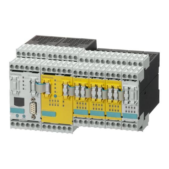
Page 38: A Typical System Configuration Of The Mss 3Rk3 Main System
• Maximum of 7 for MSS 3RK3 Basic • Maximum of 9 for MSS 3RK3 Advanced ⑬ Memory module Figure 3-1 A typical system configuration of the MSS 3RK3 main system SIRIUS 3RK3 Modular Safety System Equipment Manual, 07/2020, NEB926253002000/RS-AC/006... -
Page 39: A Typical Configuration Of The Subsystem With As-Interface
12 safety-related signals bidirectionally with an AS‑i safety monitor. Moreover, the MSS 3RK3 Advanced can mutually independently control up to 12 safety-related AS-i outputs (with up to 4 outputs). SIRIUS 3RK3 Modular Safety System Equipment Manual, 07/2020, NEB926253002000/RS-AC/006... - Page 40 Moreover, the MSS 3RK3 Advanced can mutually independently control up to 12 safety-related AS-i outputs (with up to 4 outputs). Up to 12 safety-related signals can be transmitted by the MSS 3RK3 Advanced to an F‑PLC over the F‑Link. SIRIUS 3RK3 Modular Safety System Equipment Manual, 07/2020, NEB926253002000/RS-AC/006...
- Page 41 Data exchange between MSS 3RK3 Advanced and a safety monitor ⑦ AS-i power section ⑧ ⑫ Safety-related and non-safety-related AS-i slaves Figure 3-3 A typical system configuration with MSS 3RK3 Advanced on an F‑PLC SIRIUS 3RK3 Modular Safety System Equipment Manual, 07/2020, NEB926253002000/RS-AC/006...
-
Page 42: Mss 3Rk3 System Components
Simulation of AS‑i slaves Expansion modules You need expansion modules to adapt the MSS 3RK3 to the required application. You thereby supplement the 3RK3 central unit with additional inputs and outputs. SIRIUS 3RK3 Modular Safety System Equipment Manual, 07/2020, NEB926253002000/RS-AC/006... - Page 43 3RK3 central unit or, if there is one, to the interface module. • If required, a PC or programming device can be connected to the diagnostics display. SIRIUS 3RK3 Modular Safety System Equipment Manual, 07/2020, NEB926253002000/RS-AC/006...
- Page 44 Round: – 3UF7931-0AA00-0: 0.1 m, (flat) – 3UF7935-0AA00-0: 0.3 m, (flat) – 3UF7932-0AA00-0: 0.5 m, (flat) – 3UF7932-0BA00-0: 0.5 m, (round) – 3UF7937-0BA00-0: 1 m, (round) – 3UF7933-0BA00-0: 2.5 m, (round) SIRIUS 3RK3 Modular Safety System Equipment Manual, 07/2020, NEB926253002000/RS-AC/006...
- Page 45 – Seal to protect interface against unauthor‐ ized access • Article number: 3UF7950-0AA00-0 Door adapter • For bringing out the device interface, e.g. out of a control cabinet • Article number: 3UF7920-0AA00-0 SIRIUS 3RK3 Modular Safety System Equipment Manual, 07/2020, NEB926253002000/RS-AC/006...
- Page 46 Push-in lugs for mounting the device on a level mounting the PROFI‐ surface: NET interface – 2 units for devices with width 22.5 mm – Contents 10 units • Article number: 3ZY1311-0AA00 SIRIUS 3RK3 Modular Safety System Equipment Manual, 07/2020, NEB926253002000/RS-AC/006...
-
Page 47: Features And Functions Of The Mss 3Rk3
AS-i Power24V suitable Diagnostics Diagnostics using LEDs ✓ ✓ ✓ ✓ Diagnostics using Safety ES ✓ ✓ ✓ ✓ Diagnostics using PROFINET ✓ ✓ ✓ Diagnostics using PROFIBUS ✓ ✓ ✓ ✓ SIRIUS 3RK3 Modular Safety System Equipment Manual, 07/2020, NEB926253002000/RS-AC/006... - Page 48 Control functions ✓ ✓ ✓ ✓ • Device command Logic functions • ✓ ✓ ✓ ✓ ✓ ✓ ✓ ✓ • ✓ ✓ ✓ ✓ • ✓ ✓ ✓ ✓ • NAND SIRIUS 3RK3 Modular Safety System Equipment Manual, 07/2020, NEB926253002000/RS-AC/006...
- Page 49 • Standard output ✓ ✓ ✓ ✓ ✓ ✓ ✓ ✓ • F output • Standard output delayed • F output delayed ‑ ✓ ✓ ✓ • AS‑i 1 ... 4F‑DO SIRIUS 3RK3 Modular Safety System Equipment Manual, 07/2020, NEB926253002000/RS-AC/006...
-
Page 50: Safety Systems - General Information
The safety relays described in this manual are evaluation units for safety functions. Reacting (actuators): • Switching off the hazard by means of downstream actuators Detecting Evaluating Reacting (sensors) (safety relay) (actuators) SIRIUS 3RK3 Modular Safety System Equipment Manual, 07/2020, NEB926253002000/RS-AC/006... -
Page 51: What Is Safety
The first step is, therefore, to identify the risk of a use case. In order to make a reliable assessment regarding the application, each individual function of a machine or plant must be analyzed for potential hazards. You can find further information on the Siemens Safety Integrated (http://www.siemens.com/ safety) Internet page. -
Page 52: Cross-Circuit Detection
NO contacts. An individual enabling circuit with two channels that is configured accordingly in the safety relay can be used for applications up to SILCL 3 / PL e / Kat. 4. SIRIUS 3RK3 Modular Safety System Equipment Manual, 07/2020, NEB926253002000/RS-AC/006... -
Page 53: Solid-State Signaling Output
This reset is generally performed by operating a button. SIRIUS 3RK3 Modular Safety System Equipment Manual, 07/2020, NEB926253002000/RS-AC/006... - Page 54 Safety devices for inaccessible danger zones can use the automatic start function if this does not pose any risk. Note An automatic start is not permitted for EMERGENCY STOP devices. SIRIUS 3RK3 Modular Safety System Equipment Manual, 07/2020, NEB926253002000/RS-AC/006...
- Page 55 (misuse). For PL e n accordance with EN ISO 13849‑1 as well as SILCL 3 in accordance with EN 62061, monitored start must be used in the case of EMERGENCY STOP. For SIRIUS 3RK3 Modular Safety System Equipment Manual, 07/2020, NEB926253002000/RS-AC/006...
-
Page 56: Two-Hand Operation/Synchronism
Note The two-hand circuit must be marked in compliance with EN 574 or EN ISO 13851. You can find information on determining the response time in Section Response times (Page 171). SIRIUS 3RK3 Modular Safety System Equipment Manual, 07/2020, NEB926253002000/RS-AC/006... -
Page 57: Discrepancy Monitoring
Unauthorized manipulation of the protection equipment can also be detected through startup testing. The plant operator decides whether startup testing should be performed (risk assessment). No general statements apply. SIRIUS 3RK3 Modular Safety System Equipment Manual, 07/2020, NEB926253002000/RS-AC/006... -
Page 58: Series Connection Of Sensors
For safety level SILCL3 in accordance with EN 62061, SIL3 in accordance with IEC 61508, and PL e (Cat. 4) in accordance with ISO 13849-1, however, they must never be connected in series, because every hazardous error must be detected (independently of the operating personnel). SIRIUS 3RK3 Modular Safety System Equipment Manual, 07/2020, NEB926253002000/RS-AC/006... - Page 59 Overview 3.7 Safety systems - General information ① Mechanical position switch ② Closed ③ Open ④ Safety relay SIRIUS 3RK3 Modular Safety System Equipment Manual, 07/2020, NEB926253002000/RS-AC/006...
- Page 60 Overview 3.7 Safety systems - General information SIRIUS 3RK3 Modular Safety System Equipment Manual, 07/2020, NEB926253002000/RS-AC/006...
-
Page 61: Getting Started With Mss 3Rk3 Basic
(MSS 3RK3) using an example demonstrating how to protect a metalworking press. The essential steps for commissioning the MSS 3RK3 are as follows: 1. Installation 2. Wiring 3. Configuring 4. Function test SIRIUS 3RK3 Modular Safety System Equipment Manual, 07/2020, NEB926253002000/RS-AC/006... -
Page 62: Hardware And Software Requirements
Safety ES (software) 3ZS1316-* To configure the modules, you need a programming device or PC with Safety ES. You will find further information in the attached README file of Safety ES. SIRIUS 3RK3 Modular Safety System Equipment Manual, 07/2020, NEB926253002000/RS-AC/006... -
Page 63: Task And Structure Of The Example
To enable switch-on by two-hand operation, the start pushbutton must be pressed after unlocking the pressed EMERGENCY STOP. ① Start pushbutton ② Two-hand operator panel ③ EMERGENCY STOP control device ④ Light curtain (ESPE) Figure 4-1 Typical system configuration SIRIUS 3RK3 Modular Safety System Equipment Manual, 07/2020, NEB926253002000/RS-AC/006... -
Page 64: Installation Of The Mss 3Rk3 Basic
Establish a connection between the 3RK3 Basic central unit (system interface X2) and the expansion module (system interface X1) by means of a connection cable (0.025 m). Figure 4-2 MSS 3RK3 configuration SIRIUS 3RK3 Modular Safety System Equipment Manual, 07/2020, NEB926253002000/RS-AC/006... -
Page 65: Wiring Of The Mss 3Rk3 Basic
Please refer here to the operating instruc‐ tions for the light curtain. Connect the EMERGENCY STOP control de‐ vice to the 3RK3 Basic central unit, with: • NC 1: Terminal T1/IN3 • NC 2: Terminal T2/IN4 SIRIUS 3RK3 Modular Safety System Equipment Manual, 07/2020, NEB926253002000/RS-AC/006... - Page 66 NO pushbutton 1: Terminal T1/IN5 • NC pushbutton 2: Terminal T2/IN8 NO pushbutton 2: Terminal T1/IN7 Connect the Start pushbutton on the expan‐ sion module 2/4 F‑DI 2F‑DO, with: • NO contact: Terminal T1/IN1 SIRIUS 3RK3 Modular Safety System Equipment Manual, 07/2020, NEB926253002000/RS-AC/006...
- Page 67 Contactor / coil QB: Terminal Q2 Connect the feedback circuit of the contac‐ tors QA and QB on the expansion module 2/4 F‑DI 2F‑DO, with: • Contactor / NC QA / QB: Terminal IN3 SIRIUS 3RK3 Modular Safety System Equipment Manual, 07/2020, NEB926253002000/RS-AC/006...
-
Page 68: Configuration Of The Mss 3Rk3 Basic
(under the 3RK3 central unit added in Step 7) in the work space for the hardware configuration. On the left of the navigation window, select the "Logic" directory and then the "Diagram 1" sub‐ directory. SIRIUS 3RK3 Modular Safety System Equipment Manual, 07/2020, NEB926253002000/RS-AC/006... -
Page 69: Creating The Safety Program
– Activate cross-circuit detection. • Select the following in the "Parameter > Start" directory: – The "Type of start" parameter, and define this as "Monitored". • Close the window by clicking "OK". SIRIUS 3RK3 Modular Safety System Equipment Manual, 07/2020, NEB926253002000/RS-AC/006... - Page 70 "SLOT3_F‑IN6". – The "IN3" parameter, and connect this to "SLOT3_F-IN7". – The "IN4" parameter is automatically set to "SLOT3F-IN8". – Activate cross-circuit detection • Close the window by clicking "OK". SIRIUS 3RK3 Modular Safety System Equipment Manual, 07/2020, NEB926253002000/RS-AC/006...
- Page 71 • Select the following in the "Parameter" direc‐ tory: – The "Number of logic inputs" parameter, and define this as "3". • Close the window by clicking "OK". SIRIUS 3RK3 Modular Safety System Equipment Manual, 07/2020, NEB926253002000/RS-AC/006...
- Page 72 (feedback circuit) of the F output. • Connect the output of the input cell "SLOT4_F-IN1" with the input "Start" of the EMERGENCY STOP monitoring function. For a clearer display, choose "Edit" > "Realign graphic". SIRIUS 3RK3 Modular Safety System Equipment Manual, 07/2020, NEB926253002000/RS-AC/006...
-
Page 73: Function Test Of The Mss 3Rk3 Basic
Place a suitable object in the protection zone of the If the two-hand operator panel is pressed again while the ESPE. light curtain is interrupted, contactors QA and QB do not pick up. SIRIUS 3RK3 Modular Safety System Equipment Manual, 07/2020, NEB926253002000/RS-AC/006... - Page 74 Set the communications interface and confirm with "OK". The project opens online. Activate the menu command "Target system" > "Safety The message "Activate safety mode" appears. mode". Confirm with "Yes". The MSS 3RK3 switches to safety mode without pass‐ word protection. SIRIUS 3RK3 Modular Safety System Equipment Manual, 07/2020, NEB926253002000/RS-AC/006...
-
Page 75: Description Of The Hardware
The 3RK3 central units have a RESET button on the front with the following functions: • Acknowledging messages • Restoring the basic factory settings • Transfer of the code tables for central units with AS-i interface SIRIUS 3RK3 Modular Safety System Equipment Manual, 07/2020, NEB926253002000/RS-AC/006... -
Page 76: 3Rk3 Basic Central Unit
• 8 safety-related, freely parameterizable sensor inputs • 1 safety-related two-channel relay output • 1 safety-related two-channel semiconductor output • 2 test outputs for sensor supply and monitoring when used with safety-related sensor inputs SIRIUS 3RK3 Modular Safety System Equipment Manual, 07/2020, NEB926253002000/RS-AC/006... - Page 77 Connection of a memory module (X3, sealable) ⑦ Label ⑧ Display LEDs ⑨ Connection of PC or programming device, 3RK3111-1AA10 interface module, diagnostics display (X1) Internal circuit diagram Figure 5-3 MSS 3RK3 Basic internal circuit diagram SIRIUS 3RK3 Modular Safety System Equipment Manual, 07/2020, NEB926253002000/RS-AC/006...
- Page 78 Confirm the acknowledgeable errors with this button. • Factory setting • Refer to Chapter "Restoring factory settings (Page 347)" Displays of the 3RK3 Basic central unit Element Meaning DEVICE Device status Group error SIRIUS 3RK3 Modular Safety System Equipment Manual, 07/2020, NEB926253002000/RS-AC/006...
- Page 79 Q1, Q2 Status of the safety-related outputs Connecting inputs and outputs You will find further information on connecting inputs and outputs in Chapter "Wiring rules for inputs and outputs (Page 134)." SIRIUS 3RK3 Modular Safety System Equipment Manual, 07/2020, NEB926253002000/RS-AC/006...
-
Page 80: Startup / Self-Test Of The Mss 3Rk3 Basic
• The 3RK3 Advanced central unit can be parameterized using Safety ES. • An additional interface module (e.g. DP interface) can be used to exchange process data with a PLC. Diagnostic data of the MSS 3RK3 are also transmitted to the PLC. SIRIUS 3RK3 Modular Safety System Equipment Manual, 07/2020, NEB926253002000/RS-AC/006... - Page 81 • Monitoring of up to 14 non-safety-related AS-i slaves • Monitoring of up to 31 safety-related AS-i input slaves You will find further information in Chapter "Connecting to the AS-i master via AS-Interface (Page 202)." SIRIUS 3RK3 Modular Safety System Equipment Manual, 07/2020, NEB926253002000/RS-AC/006...
- Page 82 Test output for inputs IN1, • Test outputs with different test signals IN3, IN5, IN7 • Connection for sensor contacts for detecting cross- Test output for inputs IN2, circuits IN4, IN6, IN8 SIRIUS 3RK3 Modular Safety System Equipment Manual, 07/2020, NEB926253002000/RS-AC/006...
- Page 83 Application of code se‐ (Page 208)" quences Displays of the 3RK3 Advanced central unit Element Meaning DEVICE Status AS‑i AS‑i error TEACH Status of the teaching of code sequences Group error SIRIUS 3RK3 Modular Safety System Equipment Manual, 07/2020, NEB926253002000/RS-AC/006...
- Page 84 Q1, Q2 Status of the safety-related outputs Connecting inputs and outputs You will find further information on connecting inputs and outputs in Chapter "Wiring rules for inputs and outputs (Page 134)." SIRIUS 3RK3 Modular Safety System Equipment Manual, 07/2020, NEB926253002000/RS-AC/006...
-
Page 85: Startup / Self-Test Of The Mss 3Rk3 Advanced
AS‑i slaves also remains active. Only when a new configuration is loaded onto the device will the period for transmission stop the simulation of AS‑i slaves and it will not be started again until the new configuration has been evaluated and accepted. SIRIUS 3RK3 Modular Safety System Equipment Manual, 07/2020, NEB926253002000/RS-AC/006... -
Page 86: 3Rk3 Asisafe Basic Central Unit
Inputs and outputs The 3RK3 ASIsafe basic central unit has the following inputs and outputs: • 2 safety-related, freely parameterizable sensor inputs • 6 standard inputs • 1 safety-related two-channel relay output SIRIUS 3RK3 Modular Safety System Equipment Manual, 07/2020, NEB926253002000/RS-AC/006... - Page 87 RESET button ④ Removable terminal block A ⑤ External memory module (X3; sealable) ⑥ Label ⑦ Display LEDs ⑧ Connection of PC or programming device, interface module, diagnostics display (X1) 3RK3121-1AC00 SIRIUS 3RK3 Modular Safety System Equipment Manual, 07/2020, NEB926253002000/RS-AC/006...
- Page 88 Connection of PC or programming device, interface mod‐ ule, diagnostics display External memory module Slot for external memory module with parameterization data The memory module is sealable with the 3RK3 central unit or the control cabinet. SIRIUS 3RK3 Modular Safety System Equipment Manual, 07/2020, NEB926253002000/RS-AC/006...
- Page 89 Q1, Q2 Status of the safety-related outputs Connecting inputs and outputs You will find further information on connecting inputs and outputs in Chapter "Wiring rules for inputs and outputs (Page 134)." SIRIUS 3RK3 Modular Safety System Equipment Manual, 07/2020, NEB926253002000/RS-AC/006...
-
Page 90: Startup/Self-Test Of The Mss 3Rk3 Asisafe Basic
• Connection of the diagnostics display is possible as an option for time-saving diagnostics. • Connection to AS-Interface is possible for safety-related and non-safety-related data exchange. • The 3RK3 ASIsafe extended central unit is suitable for AS-i Power 24 V. SIRIUS 3RK3 Modular Safety System Equipment Manual, 07/2020, NEB926253002000/RS-AC/006... - Page 91 • Monitoring of up to 14 non-safety-related AS-i slaves • Monitoring of up to 31 safety-related AS-i input slaves You will find further information in Chapter "Connecting to the AS-i master via AS-Interface (Page 202)." SIRIUS 3RK3 Modular Safety System Equipment Manual, 07/2020, NEB926253002000/RS-AC/006...
- Page 92 Terminal Meaning Description Test output for inputs • Test outputs with different test signals F‑IN1, F‑IN3 • Connection for sensor contacts for detecting cross- Test output for inputs circuits F‑IN2, F‑IN4 SIRIUS 3RK3 Modular Safety System Equipment Manual, 07/2020, NEB926253002000/RS-AC/006...
- Page 93 Displays of the 3RK3 ASIsafe extended central unit Element Meaning DEVICE Device status AS‑i AS‑i error TEACH Status of the teaching of code sequences Group error F‑IN1 ... F‑IN4 Status of the sensor inputs SIRIUS 3RK3 Modular Safety System Equipment Manual, 07/2020, NEB926253002000/RS-AC/006...
- Page 94 Q1, Q2 Status of the safety-related outputs Connecting inputs and outputs You will find further information on connecting inputs and outputs in Chapter "Wiring rules for inputs and outputs (Page 134)." SIRIUS 3RK3 Modular Safety System Equipment Manual, 07/2020, NEB926253002000/RS-AC/006...
-
Page 95: Startup/Self-Test Of The Mss 3Rk3 Asisafe Extended
Startup/self-test of the MSS 3RK3 ASIsafe extended The startup process is similar to the startup of the MSS 3RK3 Advanced, as described in Chapter "Startup / self-test of the MSS 3RK3 Advanced (Page 85)." SIRIUS 3RK3 Modular Safety System Equipment Manual, 07/2020, NEB926253002000/RS-AC/006... -
Page 96: General Information On Expansion Modules
LEDs of the 3RK3 central unit and the expansion modules light up (lamp test). When the system has powered up, the self-test is complete, and the device is in safety or test mode, the LEDs light up in accordance with the pending signals. SIRIUS 3RK3 Modular Safety System Equipment Manual, 07/2020, NEB926253002000/RS-AC/006... -
Page 97: Expansion Module 4/8F-Di
Removable terminal block D ② Removable terminal block C ③ System interface (X2) ④ Label ⑤ Removable terminal block A ⑥ Removable terminal block B ⑦ Display LEDs ⑧ System interface (X1) SIRIUS 3RK3 Modular Safety System Equipment Manual, 07/2020, NEB926253002000/RS-AC/006... - Page 98 Connection of expansion module Displays of the expansion module 4/8F-DI Element Meaning SF / IN1 Group error / status of the sensor input IN2 ... IN8 Status of the sensor inputs SIRIUS 3RK3 Modular Safety System Equipment Manual, 07/2020, NEB926253002000/RS-AC/006...
- Page 99 Description of the hardware 5.1 Description of the individual modules Connecting inputs and outputs You will find further information on connecting inputs and outputs in Chapter "Wiring rules for inputs and outputs (Page 134)." SIRIUS 3RK3 Modular Safety System Equipment Manual, 07/2020, NEB926253002000/RS-AC/006...
-
Page 100: Expansion Module 2/4F-Di 1/2F-Ro
Removable terminal block D ② Removable terminal block C ③ System interface (X2) ④ Label ⑤ Removable terminal block A ⑥ Removable terminal block B ⑦ Display LEDs ⑧ System interface (X1) SIRIUS 3RK3 Modular Safety System Equipment Manual, 07/2020, NEB926253002000/RS-AC/006... - Page 101 Displays of the expansion module 2/4F‑DI 1/2F‑RO Element Meaning SF / IN1 Group error / status of the sensor input IN2, IN3, IN4 Status of the sensor inputs Q1, Q2 State of the relay outputs SIRIUS 3RK3 Modular Safety System Equipment Manual, 07/2020, NEB926253002000/RS-AC/006...
- Page 102 Description of the hardware 5.1 Description of the individual modules Connecting inputs and outputs You will find further information on connecting inputs and outputs in Chapter "Wiring rules for inputs and outputs (Page 134)." SIRIUS 3RK3 Modular Safety System Equipment Manual, 07/2020, NEB926253002000/RS-AC/006...
-
Page 103: Expansion Module 2/4F-Di 2F-Do
Removable terminal block D ② Removable terminal block C ③ System interface (X2) ④ Label ⑤ Removable terminal block A ⑥ Removable terminal block B ⑦ Display LEDs ⑧ System interface (X1) SIRIUS 3RK3 Modular Safety System Equipment Manual, 07/2020, NEB926253002000/RS-AC/006... - Page 104 Displays of the expansion module 2/4F‑DI 2F‑DO Element Meaning SF / IN1 Group error / status of the sensor input IN2, IN3, IN4 Status of the sensor inputs Q1, Q2 State of semiconductor outputs SIRIUS 3RK3 Modular Safety System Equipment Manual, 07/2020, NEB926253002000/RS-AC/006...
- Page 105 Description of the hardware 5.1 Description of the individual modules Connecting inputs and outputs You will find further information on connecting inputs and outputs in Chapter "Wiring rules for inputs and outputs (Page 134)." SIRIUS 3RK3 Modular Safety System Equipment Manual, 07/2020, NEB926253002000/RS-AC/006...
-
Page 106: Expansion Module 4F-Do
Removable terminal block D ② Removable terminal block C ③ System interface (X2) ④ Label ⑤ Removable terminal block A ⑥ Removable terminal block B ⑦ Display LEDs ⑧ System interface (X1) SIRIUS 3RK3 Modular Safety System Equipment Manual, 07/2020, NEB926253002000/RS-AC/006... - Page 107 Q2, Q3, Q4 State of the semiconductor outputs Connecting inputs and outputs You will find further information on connecting inputs and outputs in Chapter "Wiring rules for inputs and outputs (Page 134)." SIRIUS 3RK3 Modular Safety System Equipment Manual, 07/2020, NEB926253002000/RS-AC/006...
-
Page 108: Expansion Module 4/8F-Ro
Removable terminal block C ③ System interface (X2) ④ Removable terminal block A ⑤ Label ⑥ Display LEDs ⑦ System interface (X1) Internal circuit diagram Figure 5-15 4/8F‑RO internal circuit diagram SIRIUS 3RK3 Modular Safety System Equipment Manual, 07/2020, NEB926253002000/RS-AC/006... - Page 109 Q2 ... Q8 State of the relay outputs Connecting inputs and outputs You will find further information on connecting inputs and outputs in Chapter "Wiring rules for inputs and outputs (Page 134)." SIRIUS 3RK3 Modular Safety System Equipment Manual, 07/2020, NEB926253002000/RS-AC/006...
-
Page 110: Expansion Module 8Di
Removable terminal block D ② Removable terminal block C ③ System interface (X2) ④ Label ⑤ Removable terminal block A ⑥ Removable terminal block B ⑦ Display LEDs ⑧ System interface (X1) SIRIUS 3RK3 Modular Safety System Equipment Manual, 07/2020, NEB926253002000/RS-AC/006... - Page 111 IN2 ... IN8 Status of the sensor inputs Connecting inputs and outputs You will find further information on connecting inputs and outputs in Chapter "Wiring rules for inputs and outputs (Page 134)." SIRIUS 3RK3 Modular Safety System Equipment Manual, 07/2020, NEB926253002000/RS-AC/006...
-
Page 112: Expansion Module 8Do
System interface (X2) ④ Label ⑤ Removable terminal block A ⑥ Removable terminal block B ⑦ Display LEDs ⑧ System interface (X1) Internal circuit diagram Figure 5-17 8DO internal circuit diagram SIRIUS 3RK3 Modular Safety System Equipment Manual, 07/2020, NEB926253002000/RS-AC/006... -
Page 113: 3Sk25 Profinet Interface Module
State of the semiconductor outputs (non-safety-related) Connecting inputs and outputs You will find further information on connecting inputs and outputs in Chapter "Wiring rules for inputs and outputs (Page 134)." 5.1.16 3SK25 PROFINET interface module SIRIUS 3RK3 Modular Safety System Equipment Manual, 07/2020, NEB926253002000/RS-AC/006... - Page 114 PC/PG (sealable). • The PROFINET interface module can be used to link non-safety-related signals of a higher- level controller with the safety relay logic. SIRIUS 3RK3 Modular Safety System Equipment Manual, 07/2020, NEB926253002000/RS-AC/006...
- Page 115 Top connections (removable terminals) ④ Labeling of top terminals, visible when cover tilted open ⑤ System interface (X2) ⑥ Labeling of bottom terminals, visible when cover tilted open ⑦ Label ⑧ PROFINET interface (X3) SIRIUS 3RK3 Modular Safety System Equipment Manual, 07/2020, NEB926253002000/RS-AC/006...
- Page 116 Connection of PC / PG, diagnostics display System interface Safety relay connection Ethernet RJ45 PROFINET connection Display elements of the PROFINET interface module Element Meaning DEVICE Status PORT PROFINET connection status Bus error Group error SIRIUS 3RK3 Modular Safety System Equipment Manual, 07/2020, NEB926253002000/RS-AC/006...
-
Page 117: 3Rk35 Dp Interface Module
• Integration into the higher-level control is performed by means of a GSD file. • The properties of the DP interface are set with Safety ES. The address can also be set directly on the device. SIRIUS 3RK3 Modular Safety System Equipment Manual, 07/2020, NEB926253002000/RS-AC/006... - Page 118 Removable terminal block A ⑥ SET and MODE keys for operating the device display ⑦ Label ⑧ LCD display ⑨ Display LEDs ⑩ Connection of PC / PG, diagnostics display (X1) SIRIUS 3RK3 Modular Safety System Equipment Manual, 07/2020, NEB926253002000/RS-AC/006...
- Page 119 Operating the display See Chapter "Operating the 3RK35 DP interface (Page 197)". MODE Operating the display Display elements of the DP interface module Element Meaning DEVICE Status Bus error Group error SIRIUS 3RK3 Modular Safety System Equipment Manual, 07/2020, NEB926253002000/RS-AC/006...
-
Page 120: 3Sk26 Diagnostics Display
MSS 3RK3 Basic is supported by the 3RK36 diagnostics display as from product version E01 and higher and/or the 3SK26 diagnostics display. Diagnostics display 3SK26 3RK36 3RK36 V1.0 / E01 V1.1 / E03 V1.0 / as from E01 3SK2 3RK3 Basic 3RK3 Advanced / ASIsafe SIRIUS 3RK3 Modular Safety System Equipment Manual, 07/2020, NEB926253002000/RS-AC/006... - Page 121 ④ Park position for interface cov‐ ⑤ Keys for menu navigation ⑥ Display LED ⑦ Functional ground ⑧ System interface (X2) for connection to safety relay Rear view: or interface module SIRIUS 3RK3 Modular Safety System Equipment Manual, 07/2020, NEB926253002000/RS-AC/006...
- Page 122 Meaning Keys Navigation in the operator control menu/error acknowledge‐ ment Displays Element Meaning DEVICE Status Bus error Group error Operating the diagnostics display See Chapter "Diagnostics with diagnostics display (Page 328)". SIRIUS 3RK3 Modular Safety System Equipment Manual, 07/2020, NEB926253002000/RS-AC/006...
-
Page 123: Mounting / Installing / Attaching
Can Cause Death, Serious Injury, or Damage to Property. Hazardous voltages can cause electric shock, burns and damage to property. Turn off and lock out all power supplying the system and device before working on the device. SIRIUS 3RK3 Modular Safety System Equipment Manual, 07/2020, NEB926253002000/RS-AC/006... - Page 124 Maximum of 2 for MSS 3RK3 ASIsafe extended • Maximum of 7 for MSS 3RK3 Basic • Maximum of 9 for MSS 3RK3 Advanced ⑨ Memory module Figure 5-23 Maximum cable lengths of the MSS 3RK3 SIRIUS 3RK3 Modular Safety System Equipment Manual, 07/2020, NEB926253002000/RS-AC/006...
-
Page 125: Mounting The Central Unit, Expansion Module, Or Dp Interface Module On A Din Rail
• Two screws with a maximum thread diameter of 4.8 mm • Two push-in lugs for screw fixing Refer to the accessories list for the relevant article number in Section "MSS 3RK3 system components (Page 42)". SIRIUS 3RK3 Modular Safety System Equipment Manual, 07/2020, NEB926253002000/RS-AC/006... -
Page 126: Mounting The Profinet Interface On A Standard Mounting Rail
Mounting the PROFINET interface on a standard mounting rail Requirements • A horizontal 35 mm wide mounting rail in accordance with EN 60715 has been properly secured at the installation location. SIRIUS 3RK3 Modular Safety System Equipment Manual, 07/2020, NEB926253002000/RS-AC/006... -
Page 127: Mounting The Profinet Interface On A Level Surface
• Two M4 x 12 head screws to fit the holes in accordance with DIN 784 • Two push-in lugs for screw fixing Refer to the accessories list for the relevant article number in the chapter "MSS 3RK3 system components (Page 42)". SIRIUS 3RK3 Modular Safety System Equipment Manual, 07/2020, NEB926253002000/RS-AC/006... -
Page 128: Installing The Diagnostics Display In A Control Cabinet Door / Switchboard
The degree of protection IP54 on the front is only guaranteed if: • The device has been properly installed with the fixing elements supplied. • The device interface on the front is covered with an interface cover. SIRIUS 3RK3 Modular Safety System Equipment Manual, 07/2020, NEB926253002000/RS-AC/006... -
Page 129: Removing The Central Unit, Expansion Module, Or Dp Interface Module From A Level Surface
Can Cause Death, Serious Injury, or Property Damage. Before starting work, therefore, disconnect the system and devices from the power supply. Requirements • The interface connections are disconnected. • The terminal blocks have been removed or disconnected. SIRIUS 3RK3 Modular Safety System Equipment Manual, 07/2020, NEB926253002000/RS-AC/006... -
Page 130: Removing The Central Unit, Expansion Module, Or Dp Interface Module From A Din Rail
Can Cause Death, Serious Injury, or Property Damage. Before starting work, therefore, disconnect the system and devices from the power supply. Requirements • The interface connections are disconnected. • The terminal blocks have been removed or disconnected. SIRIUS 3RK3 Modular Safety System Equipment Manual, 07/2020, NEB926253002000/RS-AC/006... -
Page 131: Removing The Diagnostics Display
Unscrew the screws of the four fixing brackets on the rear. Remove the fixing brackets. Pull the diagnostics display out of the mounting cut-out from the front. SIRIUS 3RK3 Modular Safety System Equipment Manual, 07/2020, NEB926253002000/RS-AC/006... -
Page 132: Disassembling The Profinet Interface From A Level Surface
Disassembling devices from a standard mounting rail WARNING Hazardous Voltage Can Cause Death, Serious Injury, or Property Damage. Before starting work, therefore, disconnect the system and devices from the power supply. SIRIUS 3RK3 Modular Safety System Equipment Manual, 07/2020, NEB926253002000/RS-AC/006... - Page 133 Procedure Step Instructions Figure Press the device downwards. Pull the lower half of the device away from the DIN rail. Lift the device from the upper edge of the DIN rail. SIRIUS 3RK3 Modular Safety System Equipment Manual, 07/2020, NEB926253002000/RS-AC/006...
-
Page 134: Connecting / Wiring
Can Cause Death, Serious Injury, or Property Damage. A two-channel safety application that is parameterized with two separate monitoring functions does not achieve the same safety integrity level as a redundantly parameterized monitoring function. SIRIUS 3RK3 Modular Safety System Equipment Manual, 07/2020, NEB926253002000/RS-AC/006... - Page 135 For this purpose, separate cables must be laid to actuators/contactors. In the associated function element "F output," the output type "F output redundant" must be chosen. SIRIUS 3RK3 Modular Safety System Equipment Manual, 07/2020, NEB926253002000/RS-AC/006...
-
Page 136: Guidelines For Wiring The Mss 3Rk3
10.Since a cross-circuit is a fault that requires acknowledgment, a cross-circuit that has been rectified must be acknowledged by resetting. Wiring sensors Chapters "Connecting safety-related inputs (Page 138)" and "Connecting non-safety-related inputs (Page 139)" describe how to connect the sensors to the safety relay. SIRIUS 3RK3 Modular Safety System Equipment Manual, 07/2020, NEB926253002000/RS-AC/006... - Page 137 Wiring actuators Chapters "Connecting safety-related semiconductor outputs (Page 140)," "Connecting safety- related relay outputs (Page 141)," and "Connecting non-safety-related outputs (Page 143)" describe how to connect the actuators to the safety relay. SIRIUS 3RK3 Modular Safety System Equipment Manual, 07/2020, NEB926253002000/RS-AC/006...
-
Page 138: Connecting Safety-Related Inputs
Single-channel and two-channel sen‐ sor mixed* T1 test output for IN1, 3, 5, 7 T2 test output for IN2, 4, 6, 8 IN1 ... IN5 sensor inputs Two-channel sensors are monitored for cross-circuits SIRIUS 3RK3 Modular Safety System Equipment Manual, 07/2020, NEB926253002000/RS-AC/006... -
Page 139: Connecting Non-Safety-Related Inputs
Non-safety-related signals such as start buttons can be supplied on modules with test outputs not only in a non-floating implementation via L+ but also via the test outputs T1 / T2, just like single-channel sensors. SIRIUS 3RK3 Modular Safety System Equipment Manual, 07/2020, NEB926253002000/RS-AC/006... -
Page 140: Connecting Safety-Related Semiconductor Outputs
SIL 3 per EN 61508 or PL e per EN ISO 13849-1. Connection options Single-channel actuator wiring Two-channel actuator wiring via Two-channel actuator wiring via 1 safety-related output* 2 safety-related outputs QA/QB contactors Q1, Q2 safety-related semiconductor outputs SIRIUS 3RK3 Modular Safety System Equipment Manual, 07/2020, NEB926253002000/RS-AC/006... -
Page 141: Connecting Safety-Related Relay Outputs
A suitable protective circuit is needed for inductive loads. In this way, electromagnetic interference can be suppressed and service life increased. You will find further information in Chapter "Requirements for actuators (Page 188)." SIRIUS 3RK3 Modular Safety System Equipment Manual, 07/2020, NEB926253002000/RS-AC/006... - Page 142 If this is not possible, the actuators must be wired via two safety-related outputs; see the right- hand image. For this purpose, separate cables must be laid to actuators/contactors. In the associated function element "F output," the output type "F output redundant" must be chosen. SIRIUS 3RK3 Modular Safety System Equipment Manual, 07/2020, NEB926253002000/RS-AC/006...
-
Page 143: Connecting Non-Safety-Related Outputs
The 8DO expansion module has 8 non-safety-related semiconductor outputs. These can be used for signaling purposes, to signal system states, for example. The safety-related outputs can also be used for signaling purposes. SIRIUS 3RK3 Modular Safety System Equipment Manual, 07/2020, NEB926253002000/RS-AC/006... -
Page 144: Connecting The Central Unit, Expansion Module, Or Dp Interface
Maximum number of cables x ca‐ Maximum number of cables x ca‐ ble cross-section: ble cross-section: 1 x 0.5 … 4.0 mm 2 x 0.25 … 1.5 mm 2 x 0.5 … 2.5 mm SIRIUS 3RK3 Modular Safety System Equipment Manual, 07/2020, NEB926253002000/RS-AC/006... -
Page 145: Connecting Terminal Blocks
• Flexible cables must be fitted with end sleeves or cable lugs for connection to screw-type terminal blocks. For suitable connection cross-sections of the cables, see Chapter Connection data for terminal blocks (Page 144). SIRIUS 3RK3 Modular Safety System Equipment Manual, 07/2020, NEB926253002000/RS-AC/006... - Page 146 Insert the cable into the oval opening as far as it will go. Hold the cable in the spring-loaded terminal. ~10° Remove the screwdriver. Pull on the cable to ensure it is tight. SIRIUS 3RK3 Modular Safety System Equipment Manual, 07/2020, NEB926253002000/RS-AC/006...
-
Page 147: Connect The Interfaces (X1, X2)
• The connection cables are available as adjacent versions (0.025 m). Connection cables up to max. 2.5 m in length are available for connecting to the diagnostics display. Note Reverse polarity protection Observe the color coding and mechanical coding on the connection cables. SIRIUS 3RK3 Modular Safety System Equipment Manual, 07/2020, NEB926253002000/RS-AC/006... - Page 148 Maximum of 9 for MSS 3RK3 Advanced • 0 for MSS 3RK3 ASIsafe basic • Maximum of 2 for MSS 3RK3 ASIsafe extended ⑬ Memory module Figure 5-24 Maximum cable lengths of the MSS 3RK3 SIRIUS 3RK3 Modular Safety System Equipment Manual, 07/2020, NEB926253002000/RS-AC/006...
- Page 149 Insert the cable connector into the con‐ ① nector slot. Engage the locking mechanisms Pull on the connection cable to ensure the lock‐ ing element has engaged. Close unused interfaces with interface covers. Observe the mechanical coding. SIRIUS 3RK3 Modular Safety System Equipment Manual, 07/2020, NEB926253002000/RS-AC/006...
-
Page 150: Connecting A Diagnostics Display
You will find further information in Chapter "Grounding (Page 158)". Note ① Only the safety relay or interface module may be connected to the system interface X2 on the rear of the diagnostics display. SIRIUS 3RK3 Modular Safety System Equipment Manual, 07/2020, NEB926253002000/RS-AC/006... -
Page 151: Establishing A Profibus Dp Connection
The front cover offers the option of sealing the device interface of the diagnostics display in order to prevent unauthorized access to the system. 5.3.3.5 Establishing a PROFIBUS DP connection Configuration guidelines You can find information about the installation guidelines in Chapter "Additional documentation (Page 15)". SIRIUS 3RK3 Modular Safety System Equipment Manual, 07/2020, NEB926253002000/RS-AC/006... - Page 152 Tighten the screws on the PROFIBUS DP connec‐ tor. If the device is located at the end of the PROFI‐ BUS DP cable, switch on the terminating resistor on the PROFIBUS DP connector. SIRIUS 3RK3 Modular Safety System Equipment Manual, 07/2020, NEB926253002000/RS-AC/006...
-
Page 153: Connecting The As-I Bus
Connect AS-Interface to the AS-i terminals on the 3RK3 central unit. The blue conductor of the AS-i cable is connected to the ① terminal "ASi-" and the brown conductor to the ter‐ ② minal "ASi+" SIRIUS 3RK3 Modular Safety System Equipment Manual, 07/2020, NEB926253002000/RS-AC/006... -
Page 154: Disconnecting
Remove the PROFIBUS DP connector. Disconnecting system interfaces Step Instructions Figure Press the locking element apart and then pull the connection cable out of the connector slot of the system interface. SIRIUS 3RK3 Modular Safety System Equipment Manual, 07/2020, NEB926253002000/RS-AC/006... - Page 155 Lift the terminal block out of the mechanically ③ coded guiderail of the device Disconnecting screw-type terminals Step Instructions Figure Unscrew the screw of the screw-type terminal. Remove the cable from the unscrewed screw terminal. SIRIUS 3RK3 Modular Safety System Equipment Manual, 07/2020, NEB926253002000/RS-AC/006...
-
Page 156: Plugging In Terminal Blocks
A, B, C or D on the inside. Only use the slots shown in the diagram below. Note Plug-in sequence Connect terminal block B before terminal block A, and D before C. SIRIUS 3RK3 Modular Safety System Equipment Manual, 07/2020, NEB926253002000/RS-AC/006... -
Page 157: Inserting And Sealing The Memory Module
Depending on the specific requirements, the memory module can be sealed with a sealing wire and a suitable crimp seal: • Sealing with the control cabinet • Sealing with the 3RK3 central unit SIRIUS 3RK3 Modular Safety System Equipment Manual, 07/2020, NEB926253002000/RS-AC/006... -
Page 158: Grounding
The following components must be grounded: • FE contacts of the devices, if present • The shield, if shielded sensor and actuator cables are used SIRIUS 3RK3 Modular Safety System Equipment Manual, 07/2020, NEB926253002000/RS-AC/006... -
Page 159: Connect 3Sk25 Profinet Interface
• To ensure protection against the hazard of electric shock when the terminal cover is open, screw in all terminal screws that are not needed to clamp conductors. • Close the terminal covers and always keep them closed during operation. SIRIUS 3RK3 Modular Safety System Equipment Manual, 07/2020, NEB926253002000/RS-AC/006... -
Page 160: Terminal Assignment
With the PROFINET interface, the inside faces of the terminal covers are labeled with the designations of the relevant terminals. Assignment of the markings to the terminals is shown schematically in the two illustrations below. Figure 5-26 Upper terminal cover Figure 5-27 Lower terminal cover SIRIUS 3RK3 Modular Safety System Equipment Manual, 07/2020, NEB926253002000/RS-AC/006... -
Page 161: Terminal Coding
You can provide the terminals with coding pins (3ZY1440-1AA00). These assist you when replacing devices so as to avoid confusing terminals. Figure 5-28 Module with coding pins Figure 5-29 Stud position rotated by 60° in each case SIRIUS 3RK3 Modular Safety System Equipment Manual, 07/2020, NEB926253002000/RS-AC/006... -
Page 162: Connecting The Screw-Type Terminals
Pull on the cable to ensure it is screwed tight. 5.3.4.5 Disconnecting the screw-type terminals WARNING Hazardous Voltage Can Cause Death, Serious Injury, or Property Damage. Before starting work, therefore, disconnect the system and devices from the power supply. SIRIUS 3RK3 Modular Safety System Equipment Manual, 07/2020, NEB926253002000/RS-AC/006... -
Page 163: Connecting The Push-In Terminals
To make optimum use of available terminal area, you are advised to choose a form of crimping that creates a corresponding rectangular contour. Trapezoidal crimping is generally very highly suitable in this case. SIRIUS 3RK3 Modular Safety System Equipment Manual, 07/2020, NEB926253002000/RS-AC/006... - Page 164 • Screwdriver DIN 5264 of the size 0.5 x 3 mm (for finely-stranded conductors only) • For suitable connection cross-sections of the cables, see Section Connecting the push-in terminals (Page 163). SIRIUS 3RK3 Modular Safety System Equipment Manual, 07/2020, NEB926253002000/RS-AC/006...
-
Page 165: Disconnecting The Push-In Terminals
Can Cause Death, Serious Injury, or Property Damage. Before starting work, therefore, disconnect the system and devices from the power supply. Requirements • Screwdriver DIN 5264 of the size 0.5 x 3 mm SIRIUS 3RK3 Modular Safety System Equipment Manual, 07/2020, NEB926253002000/RS-AC/006... -
Page 166: Attaching The Terminals
Before starting work, therefore, disconnect the system and devices from the power supply. Requirements • You must have removed the terminal blocks, for the purpose of replacing a device, for example. SIRIUS 3RK3 Modular Safety System Equipment Manual, 07/2020, NEB926253002000/RS-AC/006... -
Page 167: Removing The Terminals
Slide the terminal back until it audibly engages. 5.3.4.9 Removing the terminals WARNING Hazardous Voltage Can Cause Death, Serious Injury, or Property Damage. Before starting work, therefore, disconnect the system and devices from the power supply. SIRIUS 3RK3 Modular Safety System Equipment Manual, 07/2020, NEB926253002000/RS-AC/006... -
Page 168: Establishing A 3Sk25 Profinet Interface Connection
PROFINET IO RJ45 connecting cable is available. Note Bending radii of the PN cables The bending radii that are specified in the documentation of the connecting cable must be complied with. SIRIUS 3RK3 Modular Safety System Equipment Manual, 07/2020, NEB926253002000/RS-AC/006... - Page 169 Description of the hardware 5.3 Connecting / wiring How to connect to PROFINET Step Instructions Figure Plug the PROFINET connector into the PROFINET interface until it audibly clicks into place. SIRIUS 3RK3 Modular Safety System Equipment Manual, 07/2020, NEB926253002000/RS-AC/006...
-
Page 170: Disassembly Of The Profinet Connector
PROFINET connector. Unlock the connector by pressing the handle of the screwdriver to the left. Press and hold the handle of the screwdriver to the left and pull the PROFINET connector off. SIRIUS 3RK3 Modular Safety System Equipment Manual, 07/2020, NEB926253002000/RS-AC/006... -
Page 171: Operation
If field bus signals are logically combined, runtime synchronism must be considered. It is the responsibility of the manufacturer to ensure that the system or machine is functioning properly as a whole. SIRIUS 3RK3 Modular Safety System Equipment Manual, 07/2020, NEB926253002000/RS-AC/006... -
Page 172: Reaction Time Of The Logic (In Error-Free Operation)
Reaction time of the logic (in error-free operation) Program cycle time of the MSS 3RK3 CYCL Input delay for monitoring functions and input cells at the inputs DELAY Timer functions in the logic (timer) TIMER SIRIUS 3RK3 Modular Safety System Equipment Manual, 07/2020, NEB926253002000/RS-AC/006... -
Page 173: Fault Reaction Time Of The Logic (Single-Channel Actuator Circuit)
Fault reaction time of the logic for a two-channel actuator circuit Fault reaction time of the logic (two- = (2 x t ) + t FRL2 CYCL DELAY TIMER channel actuator circuit) SIRIUS 3RK3 Modular Safety System Equipment Manual, 07/2020, NEB926253002000/RS-AC/006... -
Page 174: Reaction Times "Sensor - Actuator
– "OFF signal" means the change from the ON state to the OFF state (1 → 0). – "ON signal" means the change from the OFF state to the ON state (0 → 1). SIRIUS 3RK3 Modular Safety System Equipment Manual, 07/2020, NEB926253002000/RS-AC/006... - Page 175 In this case, the reaction time of input terminals t or the reaction time of the output terminals t is 256 x t + 16 s. CYCLasi Figure 6-4 Reaction times "sensor - actuator" - Part 1 SIRIUS 3RK3 Modular Safety System Equipment Manual, 07/2020, NEB926253002000/RS-AC/006...
- Page 176 Reaction time of the system from a sensor (S) to an actuator (A) (in error-free operation) Fault reaction time of the system from a sensor (S) to an actuator (A) FRSA SIRIUS 3RK3 Modular Safety System Equipment Manual, 07/2020, NEB926253002000/RS-AC/006...
- Page 177 Reaction time of the MSS 3RK3 in case of an error on the AS-i bus: Max. 32 ms FAULTasi Reaction time of the AS-i actuator in case of an error on the AS-i bus: see the documen‐ FAULTasi-A tation of the AS-i actuator SIRIUS 3RK3 Modular Safety System Equipment Manual, 07/2020, NEB926253002000/RS-AC/006...
-
Page 178: Examples Of The Total Response Time With Mss 3Rk3 Advanced
MSS 3RK3 Advanced transmits a signal to the safety-related AS-i output that shuts down the system. In this way, MSS 3RK3 controls a safety-related AS-i output. SIRIUS 3RK3 Modular Safety System Equipment Manual, 07/2020, NEB926253002000/RS-AC/006... - Page 179 Transmission duration from the logic of the MSS 3RK3 to the input terminal on the safety- related AS-i output (ASI Q) Reaction time of the logic of the MSS 3RK3 in error-free operation SIRIUS 3RK3 Modular Safety System Equipment Manual, 07/2020, NEB926253002000/RS-AC/006...
- Page 180 After taking input delay times and timer functions in the logic into account, the MSS 3RK3 Advanced opens the contactors of the system down via a safety-related output. SIRIUS 3RK3 Modular Safety System Equipment Manual, 07/2020, NEB926253002000/RS-AC/006...
- Page 181 For the reaction time of the sensor (S), see the documentation of the sensor. (If an immediate response cannot be assumed for the AS-i slave, the reaction time of the AS- i slave must also be considered at this point. Note also example 3.) SIRIUS 3RK3 Modular Safety System Equipment Manual, 07/2020, NEB926253002000/RS-AC/006...
- Page 182 After taking input delay times and timer functions in the logic into account, the second MSS 3RK3 Advanced opens the contactors of the system via two safety- related outputs. SIRIUS 3RK3 Modular Safety System Equipment Manual, 07/2020, NEB926253002000/RS-AC/006...
- Page 183 Set cycle time of MSS 3RK3 Advanced No. 1 CYCL_1 When AS-i is used, values between 15 ms and 60 ms can be set. Reaction time of the logic of the MSS 3RK3 in error-free operation SIRIUS 3RK3 Modular Safety System Equipment Manual, 07/2020, NEB926253002000/RS-AC/006...
- Page 184 RL_2 in error-free operation "sensor - actuator" (in error-free operation) Subsystem 2 Fault reaction time "sensor - ac‐ FRSA_3-1 RSA_3-1 tuator"; for two-channel actuator wiring identical to t RSA_1 Subsystem 2 SIRIUS 3RK3 Modular Safety System Equipment Manual, 07/2020, NEB926253002000/RS-AC/006...
-
Page 185: Parameterizing In Safety Es
"Central unit properties - MSS Slot 3" dialog box. – 3RK3 Basic: 10 ... 60 ms – 3RK3 Advanced/ 3RK3 ASIsafe basic/ 3RK3 ASIsafe extended: 15 ... 60 ms (With deactivated AS-Interface: 10 ... 60 ms) SIRIUS 3RK3 Modular Safety System Equipment Manual, 07/2020, NEB926253002000/RS-AC/006... - Page 186 In Safety ES there are various timer functions with which delay times can be parameterized in the logic: • With ON delay • With ON delay (trigger) • Passing make contact • Passing make contact (trigger) • With OFF delay • With OFF delay (trigger) • Clocking SIRIUS 3RK3 Modular Safety System Equipment Manual, 07/2020, NEB926253002000/RS-AC/006...
- Page 187 The delay time must be an integer multiple of the program cycle time. If that is not the case, MSS 3RK3 rounds down the delay time to an integer multiple of the program cycle time for safety reasons and Safety ES outputs a warning. SIRIUS 3RK3 Modular Safety System Equipment Manual, 07/2020, NEB926253002000/RS-AC/006...
-
Page 188: Selection Of Sensors And Actuators
The outputs of the MSS 3RK3 do not feature internal inductive interference protection. If inductive loads are operated at the solid-state outputs of the MSS 3RK3, they must be provided with inductive interference protection; see Chapter "Guidelines for inductive loads (Page 190)." SIRIUS 3RK3 Modular Safety System Equipment Manual, 07/2020, NEB926253002000/RS-AC/006... -
Page 189: Dark Test
The maximum read-back time is different on different devices: Device Maximum read-back time MSS 3RK3 central units 1 ms 2/4 F-DI 2F-DO expansion module 1 ms 4F-DO expansion module 5 ms SIRIUS 3RK3 Modular Safety System Equipment Manual, 07/2020, NEB926253002000/RS-AC/006... -
Page 190: Guidelines For Capacitive Loads
The effectiveness of a protective circuit depends on the respective application and must always be checked on a case-by-case basis. The components in a protective circuit must always be rated in line with the relevant application. SIRIUS 3RK3 Modular Safety System Equipment Manual, 07/2020, NEB926253002000/RS-AC/006... - Page 191 The diagrams show examples of protective circuits Example: for inductive loads. You will find details of protec‐ Protective circuit for an inductive load tive circuits from SIEMENS in the catalog and the relevant documentation. SIRIUS 3RK3 Modular Safety System Equipment Manual, 07/2020, NEB926253002000/RS-AC/006...
-
Page 192: Commissioning
Test mode can only be accessed online from configuration mode using a PG/PC and a password- protected command. You can switch to test mode even if the configuration has not been released. SIRIUS 3RK3 Modular Safety System Equipment Manual, 07/2020, NEB926253002000/RS-AC/006... - Page 193 • The memory module (45 mm unit) is missing or defective: In this case, only the diagnostics of the safety relay is possible (DEVICE LED flashes red, SF LED lights up red). SIRIUS 3RK3 Modular Safety System Equipment Manual, 07/2020, NEB926253002000/RS-AC/006...
-
Page 194: Integrating Into Dp Master Systems
Safety ES. If you operate several safety relays in one PROFIBUS network, you must assign a separate password for each safety relay to prevent confusion when accessing via PROFIBUS. In other words, the passwords must not be identical. SIRIUS 3RK3 Modular Safety System Equipment Manual, 07/2020, NEB926253002000/RS-AC/006... -
Page 195: Configuring In Step 7 With Gsd File
You require a GSD file for the DP interface. You can download this file from the Internet (http:// support.automation.siemens.com/WW/view/en/113630): If you want to use the DP interface as a DP slave, your configuring tool must support GSD files - Rev. 5. SIRIUS 3RK3 Modular Safety System Equipment Manual, 07/2020, NEB926253002000/RS-AC/006... -
Page 196: Failure And Restoration In The Case Of Profibus
"0" for the PROFIBUS logic inputs. Safety mode is not exited. The bus failure can be diagnosed in Safety ES. Indication failure PROFIBUS DP interface DP interface display Safety relay DEVICE Green Green DPXXX SIRIUS 3RK3 Modular Safety System Equipment Manual, 07/2020, NEB926253002000/RS-AC/006... -
Page 197: Operating The 3Rk35 Dp Interface
Figure 6-18 DP interface module Display The display has two device statuses: • Standard mode with status display • Menu mode: – Setting the DP address – Resetting to factory settings SIRIUS 3RK3 Modular Safety System Equipment Manual, 07/2020, NEB926253002000/RS-AC/006... -
Page 198: Standard Mode With Status Display
To scroll through the messages, press "MODE". A corrected error is automatically deleted from the display. If you do not press any buttons for 30 seconds, the display automatically returns to the error with the highest priority. SIRIUS 3RK3 Modular Safety System Equipment Manual, 07/2020, NEB926253002000/RS-AC/006... -
Page 199: Menu Of The Dp Interface
Restoring the factory settings is not possible since the DP interface is in cyclic data exchange with a DP master. Figure 6-19 DP interface menu 6.4.4.4 Setting the PROFIBUS address Note Only addresses 1 to 126 can be set. Other addresses are not possible. SIRIUS 3RK3 Modular Safety System Equipment Manual, 07/2020, NEB926253002000/RS-AC/006... - Page 200 "SET" or "MODE". The display then returns to standard mode. The set PROFIBUS address is applied immediately on the bus side. You do not need to switch the power OFF / ON. SIRIUS 3RK3 Modular Safety System Equipment Manual, 07/2020, NEB926253002000/RS-AC/006...
-
Page 201: Restoring Factory Settings
Display Action 1st line: not flashing Restoring the factory settings is not permissible RST• 2nd line: flashing since the DP interface is in cyclic data exchange LOCK with a DP master. SIRIUS 3RK3 Modular Safety System Equipment Manual, 07/2020, NEB926253002000/RS-AC/006... -
Page 202: Connecting To The As-I Master Via As-Interface
The examples in this chapter are all represented with a 3RK3 Advanced central unit. However, they apply equally to all other central units with AS-i interface. However, you must note the limitations on the number of expansion modules. SIRIUS 3RK3 Modular Safety System Equipment Manual, 07/2020, NEB926253002000/RS-AC/006... -
Page 203: Communication Of Mss 3Rk3 With As-I Interface
Communication of MSS 3RK3 Advanced Reference You will find further information on AS-Interface in " AS-Interface system manual (edition 11/2008) with expansions (edition 09/2010 - for displaying and configuring see Entry ID 44365425) (http://support.automation.siemens.com/WW/view/en/26250840)." SIRIUS 3RK3 Modular Safety System Equipment Manual, 07/2020, NEB926253002000/RS-AC/006... -
Page 204: Asisafe
An MSS 3RK3 with AS-i interface can perform any function of these safe AS-i components: SIRIUS 3RK3 Modular Safety System Equipment Manual, 07/2020, NEB926253002000/RS-AC/006... -
Page 205: Addressing And Configuring As-I Components In Safety Es
In Safety ES, the real AS-i slaves are communicated to the MSS 3RK3 in the subsystem (navigation window). The hardware catalog contains all supported SIEMENS AS‑i components. Just like in the main system they can be dragged into the work space and have their AS‑i address assigned. -
Page 206: Overview Of Possible Incoming And Outgoing As-I Signals
Safety ES MSS 3RK3 ASI#xx(AB)_INc Sensor input Monitoring of non-safety-rela‐ ted AS-i slaves ASI#xx(AB)_Qc Output (master call) ASI#xx(AB)_Qc* Master call to the channel that is not part of the slave profile SIRIUS 3RK3 Modular Safety System Equipment Manual, 07/2020, NEB926253002000/RS-AC/006... - Page 207 The process image of the master call may contain more channels than the slave profile of the corresponding AS-i slave. The channels addressed here are not processed on the AS-i slave but can be used for special solutions. y.z: Defines bit position in CTT2 frame SIRIUS 3RK3 Modular Safety System Equipment Manual, 07/2020, NEB926253002000/RS-AC/006...
-
Page 208: Teaching The Code Sequences
Once the actual expanded configuration has been determined, it is compared with the predefined target configuration. AS-i slaves that were not found or that have been stored with a non-matching code sequence are calculated in the logic processing with the substitute value SIRIUS 3RK3 Modular Safety System Equipment Manual, 07/2020, NEB926253002000/RS-AC/006... - Page 209 Device in configuring mode/safety mode/test mode ering green AS-i AS‑i bus ok, code table complete TEACH yellow The code sequences have been recorded and checked and can now be stored. No error SIRIUS 3RK3 Modular Safety System Equipment Manual, 07/2020, NEB926253002000/RS-AC/006...
- Page 210 LED display after successful teaching of code sequences Behavior Explanation DEVICE yellow/green/flick‐ Device in configuring mode/safety mode/test mode ering green AS‑i AS‑i bus ok, all safety-related AS-i slaves have been taught TEACH Teaching over No error SIRIUS 3RK3 Modular Safety System Equipment Manual, 07/2020, NEB926253002000/RS-AC/006...
-
Page 211: Canceling Teaching Of Code Sequences
The resulting code sequence is checked for correctness. As soon as all code sequences have been determined, they are checked for uniqueness. SIRIUS 3RK3 Modular Safety System Equipment Manual, 07/2020, NEB926253002000/RS-AC/006... - Page 212 Double code sequences on the AS-i bus If the code sequence that a newly inserted safety-related AS‑i slave outputs is identical to an existing code sequence, the substitute value "0" is used for both slaves. SIRIUS 3RK3 Modular Safety System Equipment Manual, 07/2020, NEB926253002000/RS-AC/006...
- Page 213 When a new slave with a correct new code sequence has been inserted, the existing code sequence error must be acknowledged with the RESET button. Only then can the new code sequence be stored. SIRIUS 3RK3 Modular Safety System Equipment Manual, 07/2020, NEB926253002000/RS-AC/006...
-
Page 214: Functions Of The Mss 3Rk3 On The As-I Bus
The MSS 3RK3 is always a physical bus load from an A/B slave on the AS‑i bus. This bus load does not depend on how many slaves can be simulated by the MSS 3RK3 or whether only AS-i slaves are monitored. SIRIUS 3RK3 Modular Safety System Equipment Manual, 07/2020, NEB926253002000/RS-AC/006... -
Page 215: Safety-Related Data Exchange, For Example, In Multiple Subnetworks
It is possible to operate multiple AS‑i devices with monitor functionality on one AS‑i line. That way, they can monitor different groups of AS-i slaves on the same AS‑i line (subnets) that contain SIRIUS 3RK3 Modular Safety System Equipment Manual, 07/2020, NEB926253002000/RS-AC/006... -
Page 216: Simulated As-I Slaves
No AS‑i slaves are simulated while a new configuration is being downloaded. Therefore no simulated slaves are visible. Only after the correctness of the configuration has been evaluated are the AS‑i slaves in the new configuration simulated on the bus again. SIRIUS 3RK3 Modular Safety System Equipment Manual, 07/2020, NEB926253002000/RS-AC/006... -
Page 217: Simulation Of Non-Safety-Related As-I Slaves
(AB): A or B can be entered here if the monitored slave is an A/B slave. This identifier is omitted for standard slaves. MSS 3RK3 supports only standard slaves for CTT2. c: Channel number of AS-i slave process image y.z: Defines bit position in CTT2 frame SIRIUS 3RK3 Modular Safety System Equipment Manual, 07/2020, NEB926253002000/RS-AC/006... - Page 218 Simulation of non-safety-related AS‑i slaves In this case, the input and output terminals of the logic diagram in Safety ES have the following designations: Figure 6-24 Simulation of non-safety-related AS-i slaves in the logic diagram SIRIUS 3RK3 Modular Safety System Equipment Manual, 07/2020, NEB926253002000/RS-AC/006...
-
Page 219: Simulation Of Safety-Related As-I Input Slaves
AS-i bus. Terminal designation of the output cell Explanation SLOT3_ASI#xx-F-S1&2 Sensor signal from MSS 3RK3 to AS‑i master that can be eval‐ uated by an AS-i safety monitor xx: AS-i address SIRIUS 3RK3 Modular Safety System Equipment Manual, 07/2020, NEB926253002000/RS-AC/006... -
Page 220: Control Of Safety-Related As-I Outputs
• The MSS 3RK3 ASIsafe basic can simulate up to 8 safety-related AS‑i output slaves. • The MSS 3RK3 ASIsafe extended can simulate up to 10 safety-related AS‑i output slaves. • The MSS 3RK3 Advanced can simulate up to 12 safety-related AS‑i output slaves. SIRIUS 3RK3 Modular Safety System Equipment Manual, 07/2020, NEB926253002000/RS-AC/006... - Page 221 Interconnection in the logic diagram The AS‑i outputs are set or reset in the interconnection logic either by means of an "output cell" (Q1 only) or by means of the function element "AS‑i 1..4F‑DO." SIRIUS 3RK3 Modular Safety System Equipment Manual, 07/2020, NEB926253002000/RS-AC/006...
- Page 222 Setting/resetting of safety-related AS-i output In this case, the input and output terminals of the logic diagram in Safety ES have the following designations: Figure 6-28 Setting/resetting of safety-related AS-i output in the logic diagram SIRIUS 3RK3 Modular Safety System Equipment Manual, 07/2020, NEB926253002000/RS-AC/006...
- Page 223 AS-i output or auxiliary signals (AUX) and to monitor the switching status. Another method of interconnecting the signals in the logic is demonstrated below: Figure 6-29 Controlling safety-related AS‑i outputs using function element AS‑i 1..4F‑DO SIRIUS 3RK3 Modular Safety System Equipment Manual, 07/2020, NEB926253002000/RS-AC/006...
-
Page 224: Representation Of Safety-Related As-I Outputs
Auxiliary signal 1 or 2 xx: AS-i address c: Channel number of the AS-i slave process image, here the identifier OUT is selected as it is not a sensor value but a preprocessed signal. SIRIUS 3RK3 Modular Safety System Equipment Manual, 07/2020, NEB926253002000/RS-AC/006... - Page 225 In this case, the input and output terminals of the logic diagram in Safety ES of the right-hand MSS 3RK3 Advanced have the following designations: Figure 6-31 Evaluation of safety-related AS-i output in the logic diagram SIRIUS 3RK3 Modular Safety System Equipment Manual, 07/2020, NEB926253002000/RS-AC/006...
-
Page 226: Mss 3Rk3 Advanced As The Safety Monitor
MSS 3RK3. There are no asynchronous dependencies between the cycle time of the MSS 3RK3 and the cycle time of the AS-i bus. Reference You will find additional information on ASIsafe on the Internet (http:// support.automation.siemens.com/WW/view/en/12834652/133300). SIRIUS 3RK3 Modular Safety System Equipment Manual, 07/2020, NEB926253002000/RS-AC/006... -
Page 227: Monitoring Of Non-Safety-Related As-I Slaves
The process image of the master call may contain more channels than the slave profile of the corresponding AS-i slave. The channels addressed here are not processed on the AS-i slave but can be used in the logic. SIRIUS 3RK3 Modular Safety System Equipment Manual, 07/2020, NEB926253002000/RS-AC/006... - Page 228 In this case, the input and output terminals of the logic diagram in Safety ES have the following designations: Figure 6-33 Evaluation of the non-safety-related AS-i slave in the logic diagram SIRIUS 3RK3 Modular Safety System Equipment Manual, 07/2020, NEB926253002000/RS-AC/006...
-
Page 229: Monitoring Of Safety-Related As-I Input Slaves
AS‑i input slave is nevertheless to be used in one channel only, the second input must be bridged or assigned two single-channel sensors so that the entire code sequence can be viewed. SIRIUS 3RK3 Modular Safety System Equipment Manual, 07/2020, NEB926253002000/RS-AC/006... - Page 230 In this case, the input and output terminals of the logic diagram in Safety ES have the following designations: Figure 6-35 Evaluation of the safety-related AS‑i input slave in the logic diagram SIRIUS 3RK3 Modular Safety System Equipment Manual, 07/2020, NEB926253002000/RS-AC/006...
- Page 231 ⑤ AS‑i master Figure 6-36 Evaluation of a safety-related AS‑i input slave In this case, the input and output terminals of the logic diagram in Safety ES have the following designations: SIRIUS 3RK3 Modular Safety System Equipment Manual, 07/2020, NEB926253002000/RS-AC/006...
-
Page 232: Behavior On Failure Of As-I Components
On failure of an AS-i component, the AS‑i-LED flashes red and a warning is generated. If errors are pending on the AS-i bus (e.g. code sequence errors), the AS-i-LED lights up red. The error must be acknowledged once it has been rectified. SIRIUS 3RK3 Modular Safety System Equipment Manual, 07/2020, NEB926253002000/RS-AC/006... -
Page 233: Failure Of An As-I Slave
This can take up to 30 s. In this case, the process values of all configured AS-i slaves are assigned the substitute value "0." SIRIUS 3RK3 Modular Safety System Equipment Manual, 07/2020, NEB926253002000/RS-AC/006... - Page 234 You will find additional information in Chapter " Failure of an AS-i slave (Page 233)." SIRIUS 3RK3 Modular Safety System Equipment Manual, 07/2020, NEB926253002000/RS-AC/006...
-
Page 235: Integration Into Profinet Master Systems
3SK25 PROFINET interface / safety relay are valid. In SIRIUS Safety ES, the access paths via PROFINET services can be blocked in the "Properties interface module" in "Configuration". SIRIUS 3RK3 Modular Safety System Equipment Manual, 07/2020, NEB926253002000/RS-AC/006... -
Page 236: Setting And Transferring Device Names
Safety ES. If you operate several safety relays in one fieldbus network, you must assign a separate password for each safety relay to prevent confusion when accessing via the fieldbus. In other words, the passwords must not be identical. SIRIUS 3RK3 Modular Safety System Equipment Manual, 07/2020, NEB926253002000/RS-AC/006... - Page 237 00‑0E‑8C‑BD‑1F‑27) printed on the front of the PROFINET interface, the device can be accessible via LAN. The device name is linked with the MAC address and thus represents the MAC address. SIRIUS 3RK3 Modular Safety System Equipment Manual, 07/2020, NEB926253002000/RS-AC/006...
-
Page 238: Setting And Transferring The Ip Parameters
Note Restart of the communication Each change to the device name requires that the communication interface be restarted. A new start interrupts all Ethernet and PROFINET links and reestablishes them afterward. SIRIUS 3RK3 Modular Safety System Equipment Manual, 07/2020, NEB926253002000/RS-AC/006... - Page 239 "Ethernet addresses - Change authorizations" to "Can be changed without restrictions". The setting of the change authorizations can be changed in SIRIUS Safety ES in the "Properties interface module" dialog. SIRIUS 3RK3 Modular Safety System Equipment Manual, 07/2020, NEB926253002000/RS-AC/006...
-
Page 240: Configuring In Step 7 With Gsd File
The specification version used in the GSD file is specified in the file name. Make sure that the engineering system supports this or a newer version of the specification. Example: GSD-V2.33- SIEMENS-SIRIUS_3SK2PN-yymmdd.xml. SIRIUS 3RK3 Modular Safety System Equipment Manual, 07/2020, NEB926253002000/RS-AC/006... -
Page 241: Failure And Restoration In The Case Of Profinet
After installation of the GSD, you will find the PROFINET interface in the hardware catalog of STEP 7 V5 under "HW Catalog" > "Other Field Devices" >"PROFINET IO" > "Switching Devices" > "Siemens AG" > "Safety Switching Devices". Insert the PROFINET interface into the PROFINET IO system. - Page 242 Once the PROFINET connection has been restored, the safety relay will work with the real values again. Indication restoration PROFINET PN interface Safety relay DEVICE Green Green PORT LED Green ‑ SIRIUS 3RK3 Modular Safety System Equipment Manual, 07/2020, NEB926253002000/RS-AC/006...
-
Page 243: Operating The 3Sk25 Profinet Interface
Group error 6.7.2 Defining PROFINET communication parameters The PROFINET communication parameters of the interface module are defined in the SIRIUS Safety ES software or in automation software, e.g. STEP 7 (TIA Portal). SIRIUS 3RK3 Modular Safety System Equipment Manual, 07/2020, NEB926253002000/RS-AC/006... -
Page 244: Restoring Factory Settings
STEP 7 (TIA Portal). During this, the communication parameters, such as IP addresses or device name, station change authorizations, diagnostics deselection and, if applicable, the I&M data are deleted. The safety application is not deleted. SIRIUS 3RK3 Modular Safety System Equipment Manual, 07/2020, NEB926253002000/RS-AC/006... -
Page 245: Diagnostics / Service
A number of methods are available for diagnosing errors: • Diagnostics with Safety ES • Diagnostics with LEDs • Diagnostics via fieldbus • Diagnostics with diagnostics display • Diagnosis using AS-Interface (CTT2 protocol) SIRIUS 3RK3 Modular Safety System Equipment Manual, 07/2020, NEB926253002000/RS-AC/006... -
Page 246: Troubleshooting Procedure
3. Troubleshooting via CTT2 protocol – Via a simulated CTT2 slave that is interconnected in the logic of the MSS 3RK3, you can transfer messages to a AS-i master. SIRIUS 3RK3 Modular Safety System Equipment Manual, 07/2020, NEB926253002000/RS-AC/006... -
Page 247: Diagnostics Concept
DS92. This status is then indicated by the LEDs. Data set 92 can be read out via the diagnostics via PROFIBUS. Figure 7-1 MSS 3RK3 diagnostics concept SIRIUS 3RK3 Modular Safety System Equipment Manual, 07/2020, NEB926253002000/RS-AC/006... -
Page 248: Display Philosphy
A device error causes the system to stop. Communication between the modules is not possible. The cause of such an error is either internal system error or a defective 3RK3 central unit. SIRIUS 3RK3 Modular Safety System Equipment Manual, 07/2020, NEB926253002000/RS-AC/006... - Page 249 • yellow (in test mode) • Coming out of test mode: Following error correction, you can change back to test mode. Reset or restart leads to configuring mode. SIRIUS 3RK3 Modular Safety System Equipment Manual, 07/2020, NEB926253002000/RS-AC/006...
- Page 250 Acknowledgment is not necessary. When the logic is cor‐ ing state rect, the error is automatically canceled. flashing red The warning is signaled when the LEDs of the corresponding inputs start flash‐ ing. SIRIUS 3RK3 Modular Safety System Equipment Manual, 07/2020, NEB926253002000/RS-AC/006...
- Page 251 Display on the central unit Remedy Display DEVICE Yellow Acknowledgment is not necessary. When the parameteriza‐ tion is correct, the error is automatically canceled. SIRIUS 3RK3 Modular Safety System Equipment Manual, 07/2020, NEB926253002000/RS-AC/006...
- Page 252 Safety ES and the MSS 3RK3. The MSS 3RK3 changes from test mode to configuring mode. Display on the central unit Remedy Display DEVICE Yellow Acknowledgment is not necessary. The error is automatically canceled when a connection is re-established. SIRIUS 3RK3 Modular Safety System Equipment Manual, 07/2020, NEB926253002000/RS-AC/006...
-
Page 253: Diagnostics With Leds
To allow diagnosis by LED, only func‐ function immediately switches off all tion elements with one input and one its outputs. output can be interconnected between the input cell and the function input. SIRIUS 3RK3 Modular Safety System Equipment Manual, 07/2020, NEB926253002000/RS-AC/006... - Page 254 • Muting functions • Sequence condition not fulfilled flashing green. (muting) The sequence condition was not The error was detected at this input. fulfilled in accordance with the pa‐ rameter assignment. SIRIUS 3RK3 Modular Safety System Equipment Manual, 07/2020, NEB926253002000/RS-AC/006...
- Page 255 The way the IN LEDs flash depends on the signal that is present at the input: • Input signal present: 1.75 s ON/0.25 s OFF • Input signal not present: 0.75 s ON/1.25 s OFF SIRIUS 3RK3 Modular Safety System Equipment Manual, 07/2020, NEB926253002000/RS-AC/006...
-
Page 256: Sf" On The Expansion Module Lights Up Red
• "SF" fective and must be replaced. lights up red are off lights up red • "IN" or "Qx" • "IN" or "Q" • "DEVICE" are off are off flashes red SIRIUS 3RK3 Modular Safety System Equipment Manual, 07/2020, NEB926253002000/RS-AC/006... -
Page 257: Leds On The Modules
/ discrepancy error / feedback circuit error / sequence error / error on / 1.25 s off) during startup test) Input signal not present Q1, Q2 Output signal not present green Output signal present Please note the safety information below. SIRIUS 3RK3 Modular Safety System Equipment Manual, 07/2020, NEB926253002000/RS-AC/006... - Page 258 Reference You will find further information on the LED display during startup in Chapter "Startup / self-test of the MSS 3RK3 Basic (Page 80)" SIRIUS 3RK3 Modular Safety System Equipment Manual, 07/2020, NEB926253002000/RS-AC/006...
-
Page 259: Displays On The 3Rk3 Advanced Central Unit
/ discrepancy error / feedback circuit error / sequence error / error on / 1.25 s off) during startup test) Input signal not present Q1, Q2 Output signal not present green Output signal present Please note the safety information below. SIRIUS 3RK3 Modular Safety System Equipment Manual, 07/2020, NEB926253002000/RS-AC/006... -
Page 260: Displays On The 3Rk3 Asisafe Basic Central Unit
SET ≠ TARGET AS-i expansion TEACH Code sequences complete Flashing yellow Teaching of code sequences in progress yellow Teaching of code sequences successfully completed, code sequence ta‐ bles can now be applied SIRIUS 3RK3 Modular Safety System Equipment Manual, 07/2020, NEB926253002000/RS-AC/006... - Page 261 Reference You will find further information on the LED display during startup in Chapter "Startup / self-test of the MSS 3RK3 Advanced (Page 85)" SIRIUS 3RK3 Modular Safety System Equipment Manual, 07/2020, NEB926253002000/RS-AC/006...
-
Page 262: Displays On The 3Rk3 Asisafe Extended Central Unit
Error detected (cross-circuit at input / wirebreak / short-circuit to power (0.75 s ON/ cable / discrepancy error / feedback circuit error / sequence error / error 1.25 s OFF) during startup test) Input signal not present SIRIUS 3RK3 Modular Safety System Equipment Manual, 07/2020, NEB926253002000/RS-AC/006... - Page 263 Reference You will find further information on the LED display during startup in Chapter "Startup / self-test of the MSS 3RK3 Advanced (Page 85)" SIRIUS 3RK3 Modular Safety System Equipment Manual, 07/2020, NEB926253002000/RS-AC/006...
-
Page 264: Displays On The Expansion Module 4/8F-Di
Error detected (cross-circuit at input / wirebreak / short-circuit to power (0.75 s cable / discrepancy error / feedback circuit error / sequence error / error on / 1.25 s off) during startup test) Input signal not present SIRIUS 3RK3 Modular Safety System Equipment Manual, 07/2020, NEB926253002000/RS-AC/006... -
Page 265: Displays On Expansion Module 2/4F-Di 1/2F-Ro
/ discrepancy error / feedback circuit error / sequence error / error on / 1.25 s off) during startup test) Input signal not present Q1, Q2 Output signal not present green Output signal present SIRIUS 3RK3 Modular Safety System Equipment Manual, 07/2020, NEB926253002000/RS-AC/006... -
Page 266: Displays On Expansion Module 2/4F-Di 2F-Do
Device defective or error on the system bus (see also Chapter ""SF" on the expansion module lights up red (Page 256)") Q2, Q3, Output signal not present Green Output signal present SIRIUS 3RK3 Modular Safety System Equipment Manual, 07/2020, NEB926253002000/RS-AC/006... -
Page 267: Displays On Expansion Module 4/8F-Ro
Device defective or error on the system bus (see also Chapter ""SF" on the expansion module lights up red (Page 256)") Q2, Q3, Output signal not present Q4, Q5, green Output signal present Q6, Q7, SIRIUS 3RK3 Modular Safety System Equipment Manual, 07/2020, NEB926253002000/RS-AC/006... -
Page 268: Displays On The Profinet Interface
PROFINET interface in device power-up • PROFINET error, e.g. wrong IP address (PROFINET module is not ad‐ dressed) Red flashing PROFINET parameterization error 0.5 Hz (ratio 1:1) No group error Group error (communications error, etc.) SIRIUS 3RK3 Modular Safety System Equipment Manual, 07/2020, NEB926253002000/RS-AC/006... -
Page 269: Displays On The Dp Interface
Error, e.g. incorrect PROFIBUS address Red flashing Parameterization or configuration error 0.5 Hz (ratio 1:1) No group error Group error (communications error, etc.) Red flashing Group error: logic error (sequence, etc.) 0.5 Hz (ratio 1:1) SIRIUS 3RK3 Modular Safety System Equipment Manual, 07/2020, NEB926253002000/RS-AC/006... -
Page 270: Led Response For Various Element Functions
"1" is present for all function inputs moni‐ NCNO. tored (set as part of configuring). Cross-circuit at input A cross-circuit was detected at input x. The IN LEDs of the sensor are flashing green. SIRIUS 3RK3 Modular Safety System Equipment Manual, 07/2020, NEB926253002000/RS-AC/006... -
Page 271: Emergency Stop
"1" is present for all function inputs monitored (set as part of con‐ figuring). Cross-circuit at input x A cross-circuit was detected at input x. red The IN LEDs of the sensor are flashing green. SIRIUS 3RK3 Modular Safety System Equipment Manual, 07/2020, NEB926253002000/RS-AC/006... -
Page 272: Espe
"1" is present for all function inputs monitored (set as part of config‐ uring). Cross-circuit at input x A cross-circuit was detected at input x. red The IN LEDs of the sensor are flashing green. SIRIUS 3RK3 Modular Safety System Equipment Manual, 07/2020, NEB926253002000/RS-AC/006... -
Page 273: Protective Door
The IN LEDs of the sensor are off. This message is automatically reset if The IN2-LED is green on input type the value "1" is present for all function NCNO. inputs monitored (set as part of con‐ figuring). SIRIUS 3RK3 Modular Safety System Equipment Manual, 07/2020, NEB926253002000/RS-AC/006... -
Page 274: Protective Door With Lock
• The signal states of the inputs moni‐ tored had not all previously been reset simultaneously to the value "0" when they are set to "1" SIRIUS 3RK3 Modular Safety System Equipment Manual, 07/2020, NEB926253002000/RS-AC/006... - Page 275 Interlock not possible because Interlock not possible because the protec‐ flashes red The corresponding IN LEDs of the protective door is open tive door is open. the sensor (protective door monitoring) are flashing green. SIRIUS 3RK3 Modular Safety System Equipment Manual, 07/2020, NEB926253002000/RS-AC/006...
-
Page 276: Safety Shutdown Mat With Nc Principle
• The value "1" is not present simul‐ taneously at all available (parame‐ terized) function inputs (IN1, ...) • A cross-circuit is present in the case of cross-circuit monitoring SIRIUS 3RK3 Modular Safety System Equipment Manual, 07/2020, NEB926253002000/RS-AC/006... -
Page 277: Safety Shutdown Mat With Cross-Circuit Principle
• The value "1" is not present simulta‐ neously at all available (parameter‐ ized) function inputs (IN1, ...) • A cross-circuit is present SIRIUS 3RK3 Modular Safety System Equipment Manual, 07/2020, NEB926253002000/RS-AC/006... -
Page 278: Two-Hand Operation
Do not release both push‐ The two pushbuttons were not re‐ flashes red The IN LEDs of the sensor are buttons simultaneously leased simultaneously. flashing green. (not in the case of 3RK3 Basic) SIRIUS 3RK3 Modular Safety System Equipment Manual, 07/2020, NEB926253002000/RS-AC/006... -
Page 279: Enabling Button
The "1 out of 2...5 selection monitor‐ The IN LEDs of the sen‐ ing" has detected after the contact sor are flashing green. switchover time has elapsed: The value "1" is present at more than one input. SIRIUS 3RK3 Modular Safety System Equipment Manual, 07/2020, NEB926253002000/RS-AC/006... -
Page 280: Muting Functions
(negation) have been placed between the input cell and the element input in the logic. SIRIUS 3RK3 Modular Safety System Equipment Manual, 07/2020, NEB926253002000/RS-AC/006... -
Page 281: Output Functions
"0" is pending at the function input (IN). Start signal duration inva‐ Only with start type "Moni‐ ‑ ‑ tored start": The start signal time moni‐ toring element detected a vi‐ olation. SIRIUS 3RK3 Modular Safety System Equipment Manual, 07/2020, NEB926253002000/RS-AC/006... -
Page 282: Messages For As-I 1
Start signal duration invalid Only with start type "Moni‐ ‑ ‑ tored start": The start signal time moni‐ toring element detected a vi‐ olation. SIRIUS 3RK3 Modular Safety System Equipment Manual, 07/2020, NEB926253002000/RS-AC/006... -
Page 283: Diagnostics Via Profinet
Reading data sets with STEP 7 You can access the data sets from the user program. You will find further information on this in the document Reading data sets (https:// support.industry.siemens.com/cs/document/59192926/simatic-s7-1500-et-200mp-et-200sp- et-200al-et-200pro-diagnostics?dti=0&lc=en-WW) SIRIUS 3RK3 Modular Safety System Equipment Manual, 07/2020, NEB926253002000/RS-AC/006... - Page 284 (Page 357)". Additional information You will find more information about the SFCs and SFBs • Reference manual "System Software for S7-300/400, System and Standard Functions" • In the STEP7 online help SIRIUS 3RK3 Modular Safety System Equipment Manual, 07/2020, NEB926253002000/RS-AC/006...
-
Page 285: Description Of The Diagnostic Data Sets
Checking the bus system • PROFINET error • Check device configuration • Error on the fieldbus interface Actuator warning Group prewarning from the user program Eliminate cause of warning and ac‐ knowledge SIRIUS 3RK3 Modular Safety System Equipment Manual, 07/2020, NEB926253002000/RS-AC/006... - Page 286 Memory module defective • Programming error • Memory module too small • Self-test error (device error) • System interface configuration error Safety-related tripping Logic error (user program) Eliminate cause of message SIRIUS 3RK3 Modular Safety System Equipment Manual, 07/2020, NEB926253002000/RS-AC/006...
- Page 287 Error in configuration • Safety protocol error • Handshake error • TARGET≠ACTUAL configuration • TARGET≠ACTUAL slot expanded configura‐ tion • Memory module defective • Programming error • System interface configuration error SIRIUS 3RK3 Modular Safety System Equipment Manual, 07/2020, NEB926253002000/RS-AC/006...
-
Page 288: Diagnostics Using Profibus
You can access the data sets from the user program. Reading data sets: • S7-DPV1 master: by calling SFB 52 "RDREC" or SFC 59 "RD_REC • S7 master: by calling SFC 59 SIRIUS 3RK3 Modular Safety System Equipment Manual, 07/2020, NEB926253002000/RS-AC/006... - Page 289 ‑ Channel-specific diagnosis ‑ ID-specific diagnosis ‑ Module status ‑ Channel-specific diagnosis ‑ Byte arrangements When data longer than one byte is stored, the bytes are arranged as follows ("big endian"): SIRIUS 3RK3 Modular Safety System Equipment Manual, 07/2020, NEB926253002000/RS-AC/006...
-
Page 290: Structure Of The Diagnostics Frame
Structure of the diagnostics frame Diagnostics concept via PROFIBUS Figure 7-3 Diagnostics pyramid Byte Length Diagnostics block 0 ... 5 6 bytes Standard diagnostics DPV0 standard 6 ... 11 6 bytes ID-related diagnosis SIRIUS 3RK3 Modular Safety System Equipment Manual, 07/2020, NEB926253002000/RS-AC/006... - Page 291 CRC • Invalid parameter value • Interconnection rule violated (not in the case of MSS 3RK3 Basic) • Data structure incorrect (not in the case of MSS 3RK3 Basic) SIRIUS 3RK3 Modular Safety System Equipment Manual, 07/2020, NEB926253002000/RS-AC/006...
- Page 292 Handshake error (MSS 3RK3 Basic) Actuator warning Group warning (MSS 3RK3 Basic) or group pre‐ Eliminate cause of warning and ac‐ warning (MSS 3RK3 Advanced, MSS 3RK3 ASI‐ knowledge safe) from the user program SIRIUS 3RK3 Modular Safety System Equipment Manual, 07/2020, NEB926253002000/RS-AC/006...
- Page 293 (not for MSS 3RK3 Basic) • ASIsafe 7x4-bit code sequence errors (not for MSS 3RK3 Basic) • System interface configuration error Safety-related shutdown Logic error (user program) Eliminate cause of message SIRIUS 3RK3 Modular Safety System Equipment Manual, 07/2020, NEB926253002000/RS-AC/006...
-
Page 294: Data Set 0
0000 CPU Channel information available DS1 exists User information available Always 1 for MSS 3RK3 because diagnostics information is available via DS92 Diagnostic interrupt from substitute Not set by MS 3RK3. Reserved=0 SIRIUS 3RK3 Modular Safety System Equipment Manual, 07/2020, NEB926253002000/RS-AC/006... -
Page 295: Data Set 0 In Dp Interface
Data set 1 in the 3RK3 central unit The content of DS1 for the 3RK3 central unit is described below: Byte Meaning Note Diagnostics data part 1 ... 3 Same as DS0 Diagnostics data part 2 SIRIUS 3RK3 Modular Safety System Equipment Manual, 07/2020, NEB926253002000/RS-AC/006... - Page 296 External fault e.g. memory module not plugged in Unclear error e.g. configuration error Reserved = 0 Wiring error Logic error Configuring / test mode active ... 1 Reserved = 0 SIRIUS 3RK3 Modular Safety System Equipment Manual, 07/2020, NEB926253002000/RS-AC/006...
-
Page 297: Data Set 1 In Dp Interface
... 6 number of channels (1 channel) [1] (channel 0) module faulty (error present) [0] module OK ... 11 Reserved = 0 Unclear error e.g. configuration error ... 15 Reserved = 0 SIRIUS 3RK3 Modular Safety System Equipment Manual, 07/2020, NEB926253002000/RS-AC/006... -
Page 298: Diagnosis Using As-Interface (Ctt2 Protocol)
The diagnostic data signal the status and the operating state of the MSS 3RK3 to a higher-level control. The MSS 3RK3 can be acknowledged with RESET via the control data. SIRIUS 3RK3 Modular Safety System Equipment Manual, 07/2020, NEB926253002000/RS-AC/006... - Page 299 The acyclic CTT2 data transmission consists of up to 200 bytes of input and output data. The transmission duration of the acyclic data transmission depends on the number of AS‑i slaves and can be up to 16 s. SIRIUS 3RK3 Modular Safety System Equipment Manual, 07/2020, NEB926253002000/RS-AC/006...
-
Page 300: Cyclic Data
: user program is active ... 1 Reserved = 0 [0]: fix ... 7 SLOT3_ASI#xx-S2.0 ‑ Signal from simulated CTT2 slave of MSS 3RK3 to AS‑i master SLOT3_ASI#xx-S7.7 xx: AS-i address SIRIUS 3RK3 Modular Safety System Equipment Manual, 07/2020, NEB926253002000/RS-AC/006... - Page 301 ... 1 Reserved=0 [0]: fix ... 7 SLOT3_ASI#xx-Q2.0 ‑ Master call (CTT2 protocol) from AS-i master to simulated non-safety-related SLOT3_ASI#xx-Q7.7 AS-i slave (CTT2) of the MSS 3RK3 xx: AS-i address SIRIUS 3RK3 Modular Safety System Equipment Manual, 07/2020, NEB926253002000/RS-AC/006...
-
Page 302: Acyclic Data Transmission With Function Block
Note This FC ASi_3422 is not supported by all SIEMENS AS-i masters. You will find additional information in the documentation of the FC ASi_3422. If you are not using the FC ASi_3422, refer to the documentation of the master used and the following chapter on CTT2.. -
Page 303: Ctt2 Data Exchange
The second example below demonstrates the writing of a data set using data set DS3 "Command interface: element accesses" when there is a transmission error due to incorrect data set number (DS 4). SIRIUS 3RK3 Modular Safety System Equipment Manual, 07/2020, NEB926253002000/RS-AC/006... - Page 304 The third example below demonstrates the writing of a data set using data set DS3 "Command interface: element accesses" when an unknown CTT2 code (1E ) has been rejected: ① ② AS-i master ③ MSS 3RK3 with AS-i interface SIRIUS 3RK3 Modular Safety System Equipment Manual, 07/2020, NEB926253002000/RS-AC/006...
- Page 305 Diagnostics / service 7.6 Diagnosis using AS-Interface (CTT2 protocol) Write DS2 Read DS2 Figure 7-5 Example of transmission without error SIRIUS 3RK3 Modular Safety System Equipment Manual, 07/2020, NEB926253002000/RS-AC/006...
- Page 306 7.6 Diagnosis using AS-Interface (CTT2 protocol) ① ② AS-i master ③ MSS 3RK3 with AS-i interface Write DS2 Read DS2 Figure 7-6 Example of transmission with error because of incorrect DS number SIRIUS 3RK3 Modular Safety System Equipment Manual, 07/2020, NEB926253002000/RS-AC/006...
- Page 307 7.6 Diagnosis using AS-Interface (CTT2 protocol) ① ② AS-i master ③ MSS 3RK3 with AS-i interface Write DS2 Read DS2 Figure 7-7 Example of transmission with error because of incorrect CTT2 code SIRIUS 3RK3 Modular Safety System Equipment Manual, 07/2020, NEB926253002000/RS-AC/006...
-
Page 308: Structure Of The Transfer Protocol
You will find additional information in Chapter " Reading / writing data set 3 (Page 310)." CTT2 code Data set Command Byte exchange 29 DS3 - command interface "element Elements with errors: Read messag‐ accesses" Elements with prewarnings: Read messages SIRIUS 3RK3 Modular Safety System Equipment Manual, 07/2020, NEB926253002000/RS-AC/006... -
Page 309: Error Codes "Ctt2 Error Code
A data set that can only be read is missible in current device/ to be written system operating mode • A parameter has been changed even though it may only be changed in a particular operating mode SIRIUS 3RK3 Modular Safety System Equipment Manual, 07/2020, NEB926253002000/RS-AC/006... -
Page 310: Diagnostics Using The Ctt2 Protocol
1. Element data block Net (useful) data: The structure of the element data blocks is written in Chap‐ ter "Structure of the element data blocks (Page 311)." x+1 to x+y 2. Element data block SIRIUS 3RK3 Modular Safety System Equipment Manual, 07/2020, NEB926253002000/RS-AC/006... -
Page 311: Structure Of The Element Data Blocks
Acknowledgment button 4070 0FE6 Mode selector switch 12540 30FC Counter functions 12550 3106 Timer functions 12560 3110 Start functions 13002 32CA Muting functions 16501 4075 Switching output 17002 426A AS‑i 1...4F‑DO SIRIUS 3RK3 Modular Safety System Equipment Manual, 07/2020, NEB926253002000/RS-AC/006... -
Page 312: Element Messages
Cross-circuit at input 2 A cross-circuit was detected at input 2. Wiring error ... 7 Reserved=0 Start signal duration Only with start type "Monitored start": -‑ ‑ invalid The start signal time monitoring element detected a violation. SIRIUS 3RK3 Modular Safety System Equipment Manual, 07/2020, NEB926253002000/RS-AC/006... - Page 313 A cross-circuit was detected at input 2. Wiring error ... 1 Reserved=0 Start signal duration in‐ Only with start type "Monitored start": ‑ ‑ valid The start signal time monitoring element detec‐ ted a violation. SIRIUS 3RK3 Modular Safety System Equipment Manual, 07/2020, NEB926253002000/RS-AC/006...
- Page 314 A cross-circuit was detected at input 2. Wiring error ... 7 Reserved=0 Start signal duration invalid Only with start type "Monitored start": ‑ ‑ The start signal time monitoring element de‐ tected a violation. SIRIUS 3RK3 Modular Safety System Equipment Manual, 07/2020, NEB926253002000/RS-AC/006...
- Page 315 • The value "1" is not present simultaneously at all available (parameterized) function inputs (IN1, ...) • A cross-circuit is present in the case of cross-circuit monitoring ... 8 Reserved=0 SIRIUS 3RK3 Modular Safety System Equipment Manual, 07/2020, NEB926253002000/RS-AC/006...
- Page 316 A cross-circuit was detected at in‐ Wiring error put 2..7 Reserved=0 Start signal duration in‐ Only with start type "Monitored ‑ ‑ valid start": The start signal time monitoring element detected a violation. SIRIUS 3RK3 Modular Safety System Equipment Manual, 07/2020, NEB926253002000/RS-AC/006...
- Page 317 ‑ Reserved=0 Lock engaged The lock is engaged. ‑ ‑ Lock released The lock is released. ‑ ‑ Cross-circuit at input 1 A cross-circuit was detected at input 1. Wiring error SIRIUS 3RK3 Modular Safety System Equipment Manual, 07/2020, NEB926253002000/RS-AC/006...
- Page 318 Reserved = 0 SIRIUS 3RK3 Modular Safety System Equipment Manual, 07/2020, NEB926253002000/RS-AC/006...
- Page 319 The value "1" is not present si‐ multaneously at all available (parameterized) function in‐ puts (IN1, ...) • A cross-circuit is present in the case of cross-circuit monitor‐ ... 8 Reserved=0 SIRIUS 3RK3 Modular Safety System Equipment Manual, 07/2020, NEB926253002000/RS-AC/006...
- Page 320 • The value "1" is not present si‐ multaneously at all available (parameterized) function in‐ puts (IN1, ...) • A cross-circuit is present ... 8 Reserved=0 SIRIUS 3RK3 Modular Safety System Equipment Manual, 07/2020, NEB926253002000/RS-AC/006...
- Page 321 Cross-circuit at input 3 A cross-circuit was detected at in‐ Wiring error put 3..9 Reserved=0 Cross-circuit at input 4 A cross-circuit was detected at in‐ Wiring error put 4..9 Reserved=0 SIRIUS 3RK3 Modular Safety System Equipment Manual, 07/2020, NEB926253002000/RS-AC/006...
- Page 322 Cyclic data sition Reserved=0 Switchover time exceeded The "1 out of 2...5 selection moni‐ ‑ ‑ toring" has detected the value "0" at all inputs after the contact switchover time has elapsed. SIRIUS 3RK3 Modular Safety System Equipment Manual, 07/2020, NEB926253002000/RS-AC/006...
- Page 323 The sequence condition was not ob‐ Logic error filled served. Reserved=0 Muting display lamp defec‐ The muting display lamp - monitoring Wiring error tive function has detected an error..7 Reserved=0 SIRIUS 3RK3 Modular Safety System Equipment Manual, 07/2020, NEB926253002000/RS-AC/006...
- Page 324 Function output 1 is switch‐ ‑ ‑ ed on. Output 2 active Function output 2 is switch‐ ‑ ‑ ed on. Output 3 active Function output 3 is switch‐ ‑ ‑ ed on. SIRIUS 3RK3 Modular Safety System Equipment Manual, 07/2020, NEB926253002000/RS-AC/006...
- Page 325 Invalid output selection The value "1" was detected Logic error on more than one input IN1 ... 4 by the "1 out of 4 - selection monitoring." ... 7 Reserved=0 SIRIUS 3RK3 Modular Safety System Equipment Manual, 07/2020, NEB926253002000/RS-AC/006...
-
Page 326: Element Status
The input delay time is an exception to this because this timer is always active. Function element wait‐ A startup test is required for the corresponding function element. ‑ ing for startup test Read the element messages. SIRIUS 3RK3 Modular Safety System Equipment Manual, 07/2020, NEB926253002000/RS-AC/006... - Page 327 If an element has multiple input terminals, work continues with the substitute value for the failed terminal only. The real value is used for all the other input terminals. Read the element messages..7 reserved to x reserved SIRIUS 3RK3 Modular Safety System Equipment Manual, 07/2020, NEB926253002000/RS-AC/006...
-
Page 328: Diagnostics With Diagnostics Display
It can also be shown by selecting the menu command "Display settings / Identification" (see also Section "Display settings (Page 344)"). Diagnostics display 3SK26 3RK36 3RK36 V1.0 / E01 V1.1 / E03 V1.0 / as from E01 3SK2 SIRIUS 3RK3 Modular Safety System Equipment Manual, 07/2020, NEB926253002000/RS-AC/006... -
Page 329: Displays
Displays You can read current operating and diagnostics data, as well as status information of the safety relay in plain text, via the display. SIRIUS 3SK2 DEVICE X X X X SIRIUS 3RK3 Modular Safety System Equipment Manual, 07/2020, NEB926253002000/RS-AC/006... -
Page 330: Operator Controls And Displays On The Diagnostics Display
Display and operating elements on the diagnostics display ① Two arrow keys They serve to navigate the menu or change the display settings, e.g. to change the contrast setting or to scroll through displayed content. SIRIUS 3RK3 Modular Safety System Equipment Manual, 07/2020, NEB926253002000/RS-AC/006... - Page 331 The current assigned functions are displayed on the bottom left or right of the display. ③ LED displays Meaning DEVICE Status Bus error Group error Reference You will find additional information in Section "Displays on diagnostic display (Page 269)". SIRIUS 3RK3 Modular Safety System Equipment Manual, 07/2020, NEB926253002000/RS-AC/006...
-
Page 332: Menus
If multiple messages are pending, they are displayed as a list that is visible on the scrollbar on the right side of the display. You can scroll to the individual messages with the arrow keys. SIRIUS 3RK3 Modular Safety System Equipment Manual, 07/2020, NEB926253002000/RS-AC/006... - Page 333 You will find detailed information in Section "Display settings (Page 344)" ⑥ About SIRIUS Safety The menu option "About SIRIUS Safety" provides more information on the safety relay. SIRIUS 3RK3 Modular Safety System Equipment Manual, 07/2020, NEB926253002000/RS-AC/006...
-
Page 334: Messages
• Bus errors ⑤ • Group warning ⑥ • Group prewarning If multiple errors from different categories are pending, you can switch between the individual error categories with the arrow keys. SIRIUS 3RK3 Modular Safety System Equipment Manual, 07/2020, NEB926253002000/RS-AC/006... - Page 335 In the "Status" menu, you can acknowledge the error after having dealt with it with the right key (reset). ② Device errors Possible causes for device errors/self-test errors are: • Output wiring error • Faulty input or output • Defective device SIRIUS 3RK3 Modular Safety System Equipment Manual, 07/2020, NEB926253002000/RS-AC/006...
- Page 336 Different error causes are possible. The cause is displayed by pressing the right key (OK). Pressing the right key (OK) switches the diagnostics display directly to the relevant function element in the status menu. 3RK3 only 3RK3 Advanced and 3RK3 ASIsafe only SIRIUS 3RK3 Modular Safety System Equipment Manual, 07/2020, NEB926253002000/RS-AC/006...
- Page 337 Group prewarning from user At least 1 configured function element has a group prewarning. program Pressing the right key (OK) switches the diagnostics display directly to the element in the status menu. SIRIUS 3RK3 Modular Safety System Equipment Manual, 07/2020, NEB926253002000/RS-AC/006...
-
Page 338: Status
Safety ES. The name remains in the first line when navigating the submenu. Status information and error acknowledgment You can select the marked function element with the right key (OK) to display status information and any pending messages. SIRIUS 3RK3 Modular Safety System Equipment Manual, 07/2020, NEB926253002000/RS-AC/006... - Page 339 • Group warning • Group prewarning Possible element messages The following element messages can be diagnosed: • Pushbutton stuck • Do not release both pushbuttons • Safety sensor triggered • Protective door closed SIRIUS 3RK3 Modular Safety System Equipment Manual, 07/2020, NEB926253002000/RS-AC/006...
- Page 340 • Switchover time exceeded • Invalid operating mode selection • Incoming/outgoing alarm • Counter limit value exceeded/undershot • Last count pulse was up/down • OFF delay active • ON delay active SIRIUS 3RK3 Modular Safety System Equipment Manual, 07/2020, NEB926253002000/RS-AC/006...
-
Page 341: System Configuration
System configuration Structure of the menu Pressing of the softkeys Pressing of the arrow keys Figure 7-14 Second level of the menu of the diagnostics display - "System configuration" menu option SIRIUS 3RK3 Modular Safety System Equipment Manual, 07/2020, NEB926253002000/RS-AC/006... - Page 342 • Number of slot modules • Number of elements Slot 2 (interface module) The following information on the DP interface is available: • Reference designation (BMK) • Article number • DP address SIRIUS 3RK3 Modular Safety System Equipment Manual, 07/2020, NEB926253002000/RS-AC/006...
- Page 343 This information is only relevant in conjunction with an MSS 3RK3: The following information is available on the 3RK3 expansion modules: • Reference designation (BMK) • Article number • FW revision level SIRIUS 3RK3 Modular Safety System Equipment Manual, 07/2020, NEB926253002000/RS-AC/006...
-
Page 344: Display Settings
"Factory settings" menu option. You can access the individual submenus by pressing the right key (OK): ② • Identification ③ • Languages ④ • Contrast ⑤ • Lighting SIRIUS 3RK3 Modular Safety System Equipment Manual, 07/2020, NEB926253002000/RS-AC/006... - Page 345 This menu option specifies how long the backlit display will remain on after the last keystroke and enables permanent activation or deactivation of the backlit display. The following settings are possible: • Off • 3 s • 10 s (default setting) • 1 min SIRIUS 3RK3 Modular Safety System Equipment Manual, 07/2020, NEB926253002000/RS-AC/006...
- Page 346 The desired setting can be marked with the arrow keys. The right key (OK) selects the marked setting. A prompt for confirmation then follows that also has to be confirmed with the right key (OK). SIRIUS 3RK3 Modular Safety System Equipment Manual, 07/2020, NEB926253002000/RS-AC/006...
-
Page 347: Restoring Factory Settings
• The DP address is deleted and set to DP address 126. • For 3RK3 central units with AS-i interface, the saved code sequence table is also deleted. Note Alternatively, the factory settings can be restored by Safety ES. SIRIUS 3RK3 Modular Safety System Equipment Manual, 07/2020, NEB926253002000/RS-AC/006... - Page 348 The factory settings for the diagnostics display can also be restored; see Chapter "Display settings (Page 344)." Note Factory settings for DP interface The factory settings for the DP interface can also be restored; see Chapter "Restoring factory settings (Page 201)." SIRIUS 3RK3 Modular Safety System Equipment Manual, 07/2020, NEB926253002000/RS-AC/006...
-
Page 349: Module Replacement
Connect or disconnect the external memory module only when the power is switched off. 1. Disconnect the defective 3RK3 central unit. 2. Remove the defective 3RK3 central unit. 3. Remove the memory module with the device configuration. 4. Install the new 3RK3 central unit. SIRIUS 3RK3 Modular Safety System Equipment Manual, 07/2020, NEB926253002000/RS-AC/006... - Page 350 Take appropriate measures (e.g. start button with monitored starting) to prevent unintentional restarting and to ensure a defined start of the system. SIRIUS 3RK3 Modular Safety System Equipment Manual, 07/2020, NEB926253002000/RS-AC/006...
-
Page 351: Replacement Of As-I Components
A complete function test consists of the following tests: • Configuration test (test of the configuration) • System test (wiring test of the connected sensors and actuators) Addressing the new slave SIRIUS 3RK3 Modular Safety System Equipment Manual, 07/2020, NEB926253002000/RS-AC/006... - Page 352 Other code sequence on the AS-i bus TEACH yellow Code sequences can be applied No group error You will find further information in Chapter "Teaching the code sequences (Page 208)". SIRIUS 3RK3 Modular Safety System Equipment Manual, 07/2020, NEB926253002000/RS-AC/006...
-
Page 353: Replacing An As-I Slave In Different Subnetworks
Another code sequence in another subnet is not evalu‐ ated as an error TEACH yellow Code sequences can be applied No group error You will find further information in Chapter "Teaching the code sequences (Page 208)". SIRIUS 3RK3 Modular Safety System Equipment Manual, 07/2020, NEB926253002000/RS-AC/006... -
Page 354: Replacement Of Multiple As-I Slaves During Running Operation
3 s or by pressing the "Adopt code tables" button in the "Target system" > "ASIsafe code tables" dialog box in Safety You will find further information in Chapter "Teaching the code sequences (Page 208)". SIRIUS 3RK3 Modular Safety System Equipment Manual, 07/2020, NEB926253002000/RS-AC/006... -
Page 355: Additional As-I Slave In Running Operation
Replacement of MSS 3RK3 with AS-i interface Replacement of all 3RK3 central units is identical. Because the code sequences are stored on the memory module, the code sequences do not have to be taught as new. SIRIUS 3RK3 Modular Safety System Equipment Manual, 07/2020, NEB926253002000/RS-AC/006... - Page 356 Diagnostics / service 7.10 Replacement of AS-i components Reference You will find a description of how to replace the 3RK3 central units in Chapter "Module replacement (Page 349)." SIRIUS 3RK3 Modular Safety System Equipment Manual, 07/2020, NEB926253002000/RS-AC/006...
-
Page 357: Description Of The Diagnostic Data Sets
Reserved = 0 Operating mode change re‐ The operating status could not be ✓ ✓ jected changed. Access path closed An access path in the device is not ✓ ✓ open. SIRIUS 3RK3 Modular Safety System Equipment Manual, 07/2020, NEB926253002000/RS-AC/006... - Page 358 Reserved = 0 Release denied due to incor‐ Incorrect configuring CRC, or other F24, F16 SF, PF F24, F16 rect configuration CRC incorrect entries, e.g. no time stamp, name or description of company SIRIUS 3RK3 Modular Safety System Equipment Manual, 07/2020, NEB926253002000/RS-AC/006...
- Page 359 CRC non- matching. Factory settings restored The device contains the factory ✓ ✓ settings..23 Reserved = 0 24 ... 25 Reserved = 0 SIRIUS 3RK3 Modular Safety System Equipment Manual, 07/2020, NEB926253002000/RS-AC/006...
- Page 360 DP process data exchange Process data exchange with DP ✓ ✓ stopped master stopped. DP communication OK DP communication is OK ✓ ✓ ... 37 Reserved = 0 AS-i fieldbus interface SIRIUS 3RK3 Modular Safety System Equipment Manual, 07/2020, NEB926253002000/RS-AC/006...
- Page 361 ASIsafe 7x4-bit code se‐ At least one safety-related AS-i out‐ ‑ ✓ quence monitor active put is being simulated ... 48 Reserved = 0 SIRIUS 3RK3 Modular Safety System Equipment Manual, 07/2020, NEB926253002000/RS-AC/006...
- Page 362 System interface: (SC = system interface) SC bus error Communication error SF, BF F24, F19 SF, BF F24, F19 SC parameterization error Error occurred during the transfer ✓ ‑ of parameters to expansion mod‐ ule. SIRIUS 3RK3 Modular Safety System Equipment Manual, 07/2020, NEB926253002000/RS-AC/006...
- Page 363 • [0]: for now error • [1 ... 32767]: element no. 96 … 199 Reserved = 0 ✓: Supported ‑: Not supported SIRIUS 3RK3 Modular Safety System Equipment Manual, 07/2020, NEB926253002000/RS-AC/006...
- Page 364 Diagnostics / service 7.11 Description of the diagnostic data sets SIRIUS 3RK3 Modular Safety System Equipment Manual, 07/2020, NEB926253002000/RS-AC/006...
-
Page 365: Technical Data
Technical data Technical data in Siemens Industry Online Support Technical data sheet You can also find the technical data of the product at Siemens Industry Online Support (https:// support.industry.siemens.com/cs/ww/en/ps/16392/td). 1. Enter the full article number of the desired device in the "Product" field, and confirm with the Enter key. -
Page 366: General Technical Data
Severity level A (industry) Vibrations in accordance with EN 60068-2-6 5 ... 500 Hz • Frequency 0.75 mm • Amplitude Diagnostics display: 0 ... 60 ℃ Diagnostics display: -20 ... 70 °C SIRIUS 3RK3 Modular Safety System Equipment Manual, 07/2020, NEB926253002000/RS-AC/006... -
Page 367: 3Rk3 Basic Central Unit
Safety data according to EN ISO 13849-1 Probability of a dangerous failure per hour (PFH 5.14 x 10 Probability of a dangerous failure on demand (PFD) 1.28 x 10 Characteristic values for cables SIRIUS 3RK3 Modular Safety System Equipment Manual, 07/2020, NEB926253002000/RS-AC/006... - Page 368 Time from instant an output is switched off to the instant the output reaches a state that permits it to be switched on again. The mechanical durability may be reduced, depending on the contact load. SIRIUS 3RK3 Modular Safety System Equipment Manual, 07/2020, NEB926253002000/RS-AC/006...
-
Page 369: 3Rk3 Advanced Central Unit
Safety data according to EN ISO 13849-1 Probability of a dangerous failure per hour (PFH 2.8 x 10 1/h (without use of AS-i) 3.8 x 10 1/h (with use of AS-i) SIRIUS 3RK3 Modular Safety System Equipment Manual, 07/2020, NEB926253002000/RS-AC/006... - Page 370 Time from instant an output is switched off to the instant the output reaches a state that permits it to be switched on again. The mechanical durability may be reduced, depending on the contact load. SIRIUS 3RK3 Modular Safety System Equipment Manual, 07/2020, NEB926253002000/RS-AC/006...
-
Page 371: 3Rk3 Asisafe Basic Central Unit
Max. protection of relay contacts with fuses NH type 3NA, DIAZED type 5SB, NEOZED type 5SE • Operating class gL/gG • Operating class quick response Safety data according to EN ISO 13849-1 SIRIUS 3RK3 Modular Safety System Equipment Manual, 07/2020, NEB926253002000/RS-AC/006... - Page 372 Time from instant an output is switched off to the instant the output reaches a state that permits it to be switched on again. The mechanical durability may be reduced, depending on the contact load. SIRIUS 3RK3 Modular Safety System Equipment Manual, 07/2020, NEB926253002000/RS-AC/006...
-
Page 373: 3Rk3 Asisafe Extended Central Unit
Max. protection of relay contacts with fuses NH type 3NA, DIAZED type 5SB, NEOZED type 5SE • Operating class gL/gG • Operating class quick response Safety data according to EN ISO 13849-1 SIRIUS 3RK3 Modular Safety System Equipment Manual, 07/2020, NEB926253002000/RS-AC/006... - Page 374 Time from instant an output is switched off to the instant the output reaches a state that permits it to be switched on again. The mechanical durability may be reduced, depending on the contact load. SIRIUS 3RK3 Modular Safety System Equipment Manual, 07/2020, NEB926253002000/RS-AC/006...
-
Page 375: Em 4/8F-Di
Characteristic values for cables Max. permissible cable resistance 100 Ω Max. permissible cable length from device to sensor 1000 m (for CU 1.5 mm and 150 nF/km) Max. permissible cable capacitance 330 nF SIRIUS 3RK3 Modular Safety System Equipment Manual, 07/2020, NEB926253002000/RS-AC/006... -
Page 376: Em 2/4F-Di 1/2F-Ro
Max. permissible cable length from device to sensor 1000 m (for CU 1.5 mm and 150 nF/km) Max. permissible cable capacitance 330 nF Protective separation, reinforced insulation 4 kV between input circuit and output contact current paths. SIRIUS 3RK3 Modular Safety System Equipment Manual, 07/2020, NEB926253002000/RS-AC/006... - Page 377 Technical data 8.8 EM 2/4F‑DI 1/2F‑RO Time from instant an output is switched off to the instant the output reaches a state that permits it to be switched on again. SIRIUS 3RK3 Modular Safety System Equipment Manual, 07/2020, NEB926253002000/RS-AC/006...
-
Page 378: Em 2/4F-Di 2F-Do
Dark period semiconductor outputs < 1 ms Time from instant an output is switched off to the instant the output reaches a state that permits it to be switched on again. SIRIUS 3RK3 Modular Safety System Equipment Manual, 07/2020, NEB926253002000/RS-AC/006... -
Page 379: Em 4F-Do
Dark period semiconductor outputs < 1 ms Time from instant an output is switched off to the instant the output reaches a state that permits it to be switched on again. SIRIUS 3RK3 Modular Safety System Equipment Manual, 07/2020, NEB926253002000/RS-AC/006... -
Page 380: Em 4/8F-Ro
Protective separation, reinforced insulation 4 kV between input circuit and output contact current paths. Time from instant an output is switched off to the instant the output reaches a state that permits it to be switched on again. SIRIUS 3RK3 Modular Safety System Equipment Manual, 07/2020, NEB926253002000/RS-AC/006... -
Page 381: Em 8Di
Characteristic values for cables Max. permissible cable resistance 100 Ω Max. permissible cable length from device to sensor 1000 m (for CU 1.5 mm and 150 nF/km) Max. permissible cable capacitance 330 nF SIRIUS 3RK3 Modular Safety System Equipment Manual, 07/2020, NEB926253002000/RS-AC/006... -
Page 382: Em 8Do
(semiconductor outputs) 0.5 A; short-circuit-proof up to 10 A • DC 13 at 24 V Max. switching frequency z at rated operational current 1000 1/h Conventional thermal current I 0.5 A SIRIUS 3RK3 Modular Safety System Equipment Manual, 07/2020, NEB926253002000/RS-AC/006... -
Page 383: Profinet Interface Module
Power supply / rated control supply voltage Us 24 V DC (to IEC 61131‑2) Operating range 0.85 to 1.2 x Us Rated insulation voltage U 50 V Rated impulse voltage U 800 V Rated power at U SIRIUS 3RK3 Modular Safety System Equipment Manual, 07/2020, NEB926253002000/RS-AC/006... -
Page 384: Dp Interface Module
(to IEC 61131‑2) Work area 0.85 to 1.15 x Us Rated insulation voltage U 50 V Rated impulse voltage U 500 V Total power consumption 100 mA Rated power at U 2.4 W SIRIUS 3RK3 Modular Safety System Equipment Manual, 07/2020, NEB926253002000/RS-AC/006... -
Page 385: Diagnostics Display
= 24 V DC Work area 0.85 to 1.15 x U Rated insulation voltage U 50 V Rated impulse voltage U 500 V Total power consumption 24 mA Rated power at U 0.6 W SIRIUS 3RK3 Modular Safety System Equipment Manual, 07/2020, NEB926253002000/RS-AC/006... -
Page 386: Memory Module
8.17 Memory module 8.17 Memory module Technical data of the memory module Device data Electronic supply From the 3RK3 central unit EEPROM Data storage > 40 years Deletion/write cycles 100 000 SIRIUS 3RK3 Modular Safety System Equipment Manual, 07/2020, NEB926253002000/RS-AC/006... -
Page 387: Dimension Drawings
Dimension drawings Dimension drawing of 45-mm enclosure with screw-type terminals SIRIUS 3RK3 Modular Safety System Equipment Manual, 07/2020, NEB926253002000/RS-AC/006... - Page 388 Dimension drawings Dimension drawing of 45-mm enclosure with spring-loaded terminals SIRIUS 3RK3 Modular Safety System Equipment Manual, 07/2020, NEB926253002000/RS-AC/006...
- Page 389 Dimension drawings Drilling plan for 45-mm enclosure SIRIUS 3RK3 Modular Safety System Equipment Manual, 07/2020, NEB926253002000/RS-AC/006...
- Page 390 Dimension drawings Dimension drawing: Enclosure 22.5 mm with screw terminals 14,4 22,5 SIRIUS 3RK3 Modular Safety System Equipment Manual, 07/2020, NEB926253002000/RS-AC/006...
- Page 391 Dimension drawings Dimension drawing of 22.5-mm enclosure with spring-loaded terminals SIRIUS 3RK3 Modular Safety System Equipment Manual, 07/2020, NEB926253002000/RS-AC/006...
- Page 392 Dimension drawings Drilling plan for 22.5-mm enclosure 18,8 SIRIUS 3RK3 Modular Safety System Equipment Manual, 07/2020, NEB926253002000/RS-AC/006...
-
Page 393: Diagnostics Display
Dimension drawings 9.1 Diagnostics display Diagnostics display Diagnostics display SIRIUS 3SK2 DEVICE Cut-out for diagnostics display SIRIUS 3RK3 Modular Safety System Equipment Manual, 07/2020, NEB926253002000/RS-AC/006... -
Page 394: Profinet Interface
Dimension drawings 9.2 PROFINET interface PROFINET interface 3SK25 PROFINET interface dimension drawing PROFINET interface drilling plan SIRIUS 3RK3 Modular Safety System Equipment Manual, 07/2020, NEB926253002000/RS-AC/006... -
Page 395: Dp Interface
Dimension drawings 9.3 DP interface DP interface DP interface with screw terminals DP interface with spring-loaded terminals SIRIUS 3RK3 Modular Safety System Equipment Manual, 07/2020, NEB926253002000/RS-AC/006... - Page 396 Dimension drawings 9.3 DP interface Drilling plan DP interface SIRIUS 3RK3 Modular Safety System Equipment Manual, 07/2020, NEB926253002000/RS-AC/006...
-
Page 397: Index
AS-i interface, 34 System interfaces, 149 AS-i output, 208 Terminal blocks, 145 AS-i signals in the logic diagram, 206 Connection AS‑i 1..4F‑DO Inputs, 138 Messages, 324 Non-floating sensors, 139 Outputs, 140, 144 SIRIUS 3RK3 Modular Safety System Equipment Manual, 07/2020, NEB926253002000/RS-AC/006... - Page 398 EMERGENCY STOP Diagnostics with LED, 253 Messages, 313 3RK3 Advanced central unit, 259 EN 61508:2010, 25 3RK3 ASIsafe basic central unit, 260 EN ISO 13849-1:2008, 25 3RK3 ASIsafe extended central unit, 262 SIRIUS 3RK3 Modular Safety System Equipment Manual, 07/2020, NEB926253002000/RS-AC/006...
- Page 399 Safety-related, 229 Monitoring of simulated AS-i slaves, 226 Monitoring simulated AS-i slaves, 226 Monitoring Universal Handshake error, 252 Messages, 312 HW Config, 196, 241 MSS 3RK3 diagnostics concept, 247 Muting Messages, 323 SIRIUS 3RK3 Modular Safety System Equipment Manual, 07/2020, NEB926253002000/RS-AC/006...
- Page 400 Simulated AS-i slaves Removing Safety-related, 219 Diagnostics display, 131 Simulated slaves, 85, 216 Replacing Non-safety-related, 217 AS-i slave, 351, 353 Simulating a CTT2 slave, 217 AS-i slaves (more than one), 354 SIRIUS 3RK3 Modular Safety System Equipment Manual, 07/2020, NEB926253002000/RS-AC/006...
- Page 401 Error, 212 Technical data Central unit, 367, 369, 371, 373 Diagnostics display, 385 DP interface module, 384 EM 2/4F‑DI 1/2F‑RO, 376 EM 2/4F‑DI 2F-DO, 378 EM 4/8F-DI, 375 EM 4/8F-RO, 380 SIRIUS 3RK3 Modular Safety System Equipment Manual, 07/2020, NEB926253002000/RS-AC/006...
- Page 402 Index SIRIUS 3RK3 Modular Safety System Equipment Manual, 07/2020, NEB926253002000/RS-AC/006...
Need help?
Do you have a question about the SIRIUS 3RK3 and is the answer not in the manual?
Questions and answers