
Related Manuals for Siemens Cerberus PACE Compact


Summary of Contents for Siemens Cerberus PACE Compact
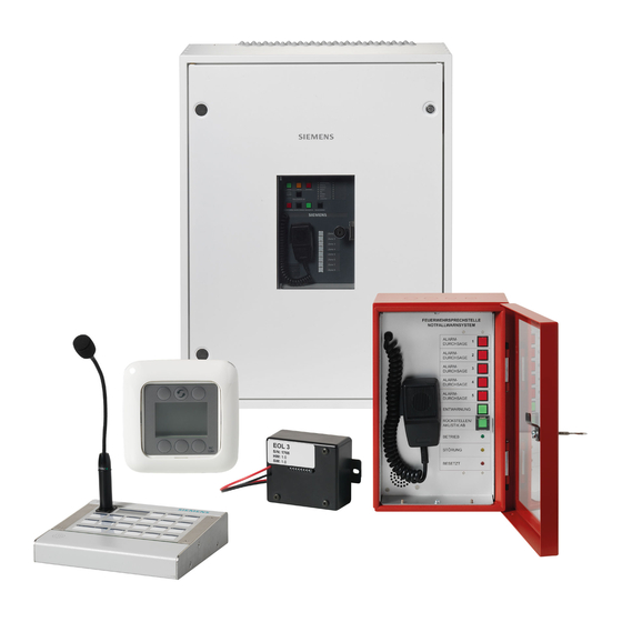
- Page 1 Cerberus PACE Compact Public Address and Controlled Evacuation Operation Manual A6V11899865_en--_b Smart Infrastructure 2021-03-12...
- Page 2 All rights created by patent grant or registration of a utility model or design patent are reserved. Issued by: Siemens Switzerland Ltd. Smart Infrastructure Global Headquarters Theilerstrasse 1a CH-6300 Zug Tel. +41 58 724-2424 www.siemens.com/buildingtechnologies Edition: 2021-03-12 Document ID: A6V11899865_en--_b © Siemens Switzerland Ltd, 2020 2 | 54 A6V11899865_en--_b...
-
Page 3: Table Of Contents
Table of contents About this document ..................5 Applicable documents ..................8 Technical terms and abbreviations ..............9 Revision history ....................9 Safety ......................10 Safety notes ....................10 Safety regulations for the method of operation ..........11 System owner ....................13 Function test / system acceptance / maintenance ........ - Page 4 12.1 Operating functions PT1001................42 12.2 Operation PT1001-A1 ................... 43 Remote control panel PT2006-A1 .............. 44 13.1 Operating functions PT2006-A1 ..............44 13.2 Operation PT2006-A1 ................... 45 Power supply in PC1002 ................46 System acceptance on site ................ 47 Commissioning and maintenance ............. 48 Appendix ......................
-
Page 5: About This Document
The information contained in this document is valid for Cerberus PACE Compact. WARNING The 'Cerberus PACE Compact' system is a Class A product. Operation of this equipment in a residential environment could cause radio interference. If so, the user must be required to take adequate measures. - Page 6 About this document Applicable documents Target groups The information in this document is intended for the following target groups: Target group Activity Qualification ● ● System owner According to EN 50110-1, 'This person can be the owner, 'nominated person with the overall employer, proprietor or a delegated responsibility to ensure the safe person.'...
- Page 7 About this document Applicable documents Source language and reference document ● The source/original language of this document is German (de). ● The reference version of this document is the international version in English. The international version is not localized. Document identification The document ID is structured as follows: ID code Examples...
-
Page 8: Applicable Documents
About this document Applicable documents 1.1 Applicable documents You will find more information on the Cerberus PACE Compact system and its components in the following documents: Title Document ID IT security policies Cerberus PACE Compact – IT security policies A6V11439692 System documentation Cerberus PACE Compact –... -
Page 9: Technical Terms And Abbreviations
About this document Technical terms and abbreviations 1.2 Technical terms and abbreviations You will find details of technical terms and abbreviations in the 'Glossary' chapter. 1.3 Revision history The reference document's version applies to all languages into which the reference document is translated. -
Page 10: Safety
Safety Safety notes 2 Safety 2.1 Safety notes Comply with the following safety notes to protect life, limb, and property. The safety notes in the document include the following elements: ● Symbol for hazard ● Signal word ● Type and source of hazard ●... -
Page 11: Safety Regulations For The Method Of Operation
2.2 Safety regulations for the method of operation National standards, regulations and legislation Siemens products are developed and produced in compliance with the relevant European and international safety standards. Should additional national or local safety standards or legislation concerning the planning, mounting, installation,... - Page 12 Siemens and the corresponding safety bodies for modifications or additions. Modules and spare parts ● Components and spare parts must comply with the technical specifications defined by Siemens. Only use products specified or recommended by Siemens. ● Only use fuses with the specified fuse characteristics. ●...
-
Page 13: System Owner
System owner Disregard of the safety regulations Before they are delivered, Siemens products are tested to ensure they function correctly when used properly. Siemens disclaims all liability for damage or injuries caused by the incorrect application of the instructions or the disregard of danger warnings contained in the documentation. -
Page 14: Standards And Directives Complied With
Safety Standards and directives complied with 2.5 Standards and directives complied with A list of the standards and directives complied with is available from your Siemens contact. 2.5.1 Multimedia equipment In the DIN EN 55032 standard (VDE 0878-32):2016-02; EN 55032:2015 'Electromagnetic compatibility of multimedia equipment –... -
Page 15: Cyber Security Disclaimer
Siemens’ portfolio undergoes continuous development to make it more secure. Siemens strongly recommends that updates are applied as soon as they are available and that the latest versions are used. Use of versions that are no longer supported, and failure to apply the latest updates may increase your exposure to cyber threats. -
Page 16: Operating Conditions
Operating conditions Operating condition indicators 3 Operating conditions The ↑ voice alarm control and indicating equipment (VACIE) or voice alarm system has the following operating conditions: ● Quiescent condition ● Voice alarm condition ● Fault warning condition 3.1 Operating condition indicators Indicating element colors The light-emitting indicating elements display the operating conditions as follows: ↑... -
Page 17: Operating Elements In The System
Operating and call stations 4 Operating elements in the system The operating elements in a Cerberus PACE Compact voice alarm system are the call stations and operating terminals with which you can make live announcements and play emergency tones and recorded messages in a targeted manner. - Page 18 EN 54-16-compliant indicator panel for visual and acoustic status messages and controlling voice alarms ● Call station with 8 configurable and illuminated zone buttons ● For installation in a Cerberus PACE Compact cabinet door ● Lockable viewing front door ● Insertable labels for custom button identification ●...
-
Page 19: Call Stations
4.2 Call stations PT2002-A1 'Fire brigade call station (AT)' ● Alarm call station with standard-compliant housing and control panel ● Full network participant in a Cerberus PACE Compact system ● 7 standardized and configurable buttons ● 3 standardized and preconfigured displays ●... - Page 20 'Desk call station (19 buttons)' ● Call station with electret condenser microphone and gooseneck ● Full network participant in a Cerberus PACE Compact system ● 2-line text display ● Buttons and status indicators to control and monitor the Cerberus PACE Compact system by users.
- Page 21 Operating elements in the system Call stations PT2009-A1 'Desk call station (RS485, 8+1)' ● Call station with 8 configurable, illuminated zone buttons plus talk button ● Buttons are freely operable ● Electret condenser microphone with gooseneck ● Monitored microphone ● Symmetrical audio transmission, analog ●...
-
Page 22: Access Levels
Access levels 5 Access levels The access level describes one of several conditions of voice alarm control and indicating equipment (VACIE) in which an appropriately authorized user can have access to or a view of the following functions on the system: ●... -
Page 23: Operating And Call Station Pt1002-A1
Operating and call station PT1002-A1 Call stations 6 Operating and call station PT1002-A1 System ON Reset Fault Fault 10 8 pre-defined status LEDs Voice Alarm 11 8 configurable status LEDs Buzzer 12 Microphone Silence Buzzer / LED Test 13 Push to Talk button on the side of the microphone (not displayed on the figure) Start Voice Alarm... -
Page 24: Operating Functions Pt1002-A1
Operating and call station PT1002-A1 Operating functions PT1002-A1 6.1 Operating functions PT1002-A1 Operate system Function Design ◈ Activate the alarm Press the red <Start Voice Alarm> button ◈ Reset the alarm manually Press the black <Reset Voice Alarm> button ◈ Silence the alarm manually Press the green <Silence Voice Alarm>... -
Page 25: Operation Pt1002-A1
Recur fault messages The LED Fault lights up again. The fault in the system has not been rectified. 1. Inform Siemens customer support. 2. Request that maintenance be carried out by technical personnel. Silence an active buzzer The buzzer is active ◈... - Page 26 Operating and call station PT1002-A1 Operation PT1002-A1 Transmit a manual announcement / Trigger an evacuation with a manual announcement 1. Select one zone or several zones by pressing the correspondingly labeled zone buttons. Selected zone buttons light up. 2. Remove the microphone from the housing. 3.
-
Page 27: Fire Brigade Call Station Pt2002-A1 And Pt2003-A1
Fire brigade call station PT2002-A1 and PT2003-A1 Operation PT1002-A1 7 Fire brigade call station PT2002-A1 and PT2003-A1 Microphone with talk button Reset button Speaker LED 'Operation' Configurable announcement LED 'Fault' buttons All-clear button LED 'Engaged' A6V11899865_en--_b 27 | 54... -
Page 28: Operating Functions Pt2002-A1 And Pt2003-A1
Fire brigade call station PT2002-A1 and PT2003-A1 Operating functions PT2002-A1 and PT2003-A1 7.1 Operating functions PT2002-A1 and PT2003-A1 Function Design Carry out a manual 1. Lift the microphone announcement / trigger an 2. Press and hold the talk button evacuation 3. - Page 29 The fault message is reset. Recur fault messages The LED 'FAULT' lights up again. The fault in the system has not been rectified. ◈ Inform Siemens customer support. Request that maintenance be carried out by technical personnel. A6V11899865_en--_b 29 | 54...
-
Page 30: Desk Call Station (19 Buttons) Pt2001-A1
Desk call station (19 buttons) PT2001-A1 Operating functions PT2001-A1 8 Desk call station (19 buttons) PT2001-A1 Microphone LED 'ONLINE' / Fault Display LED 'ON' / Operation Configurable buttons Speaker (below LED 'ON', not shown in the graphic) You can create and print the button identification in 'PACE-Design'. 8.1 Operating functions PT2001-A1 Function Design... -
Page 31: Operation Pt2001-A1
Desk call station (19 buttons) PT2001-A1 Operation PT2001-A1 8.2 Operation PT2001-A1 Transmit a manual announcement / Trigger an evacuation with a manual announcement ● Talk button configured as switch 1. Select a zone or several zones by pressing the relevant labeled buttons. ... - Page 32 The fault message is reset. Recur fault messages The LED 'FAULT' lights up again. The fault in the system has not been rectified. ◈ Inform Siemens customer support. Request that maintenance be carried out by technical personnel. 32 | 54 A6V11899865_en--_b...
-
Page 33: Indicator Pt2001-A1
Desk call station (19 buttons) PT2001-A1 Indicator PT2001-A1 8.3 Indicator PT2001-A1 Color Status Default Description LED ON (5) Green System is in regular operating mode Call station is in alarm mode with activated alarm key or station priority is configured to 8 or higher Call station is not working (no power) LED Online (4) Correct function must be configured with 'PACE-Design':... -
Page 34: Display Information Pt2001-A1
Desk call station (19 buttons) PT2001-A1 Display information PT2001-A1 Color Status Default Description PLAY Sound Button (3) is configured as 'PLAY Sound' Green Sound is active Sound is not activated STOP Sound Button (3) is configured as 'STOP Sound' Always Record buffer Button (3) is configured as 'Record buffer' Green... -
Page 35: Key Switch For Desk Call Station Pto2002/3-A1
Key switch for desk call station PTO2002/3-A1 Operating functions PTO2002/3-A1 9 Key switch for desk call station PTO2002/3-A1 Microphone LED 'ONLINE' / Fault Display LED 'ON' / Operation Configurable buttons Key switch You can create and print the button identification in 'PACE-Design'. 9.1 Operating functions PTO2002/3-A1 Unlock/lock the call station Function... -
Page 36: Desk Call Station (Rs485, 8+1) Pt2009-A1 And Call Station Extension (Rs485, 8) Pto2006-A1
Desk call station (RS485, 8+1) PT2009-A1 and Call station extension (RS485, 8) PTO2006-A1 Operating functions PT2009-A1 10 Desk call station (RS485, 8+1) PT2009-A1 and Call station extension (RS485, 8) PTO2006-A1 ZONE9 ZONE1 ZONE10 ZONE2 ZONE11 ZONE3 ZONE12 ZONE4 ZONE13 ZONE5 ZONE14 ZONE6 ZONE15... -
Page 37: Operation Pt2009-A1
Desk call station (RS485, 8+1) PT2009-A1 and Call station extension (RS485, 8) PTO2006-A1 Operation PT2009-A1 10.2 Operation PT2009-A1 Transmit a manual announcement / Trigger an evacuation with a manual announcement ● Talk button configured as switch 1. Select a zone or several zones by pressing the correspondingly labeled zone buttons. -
Page 38: Indicator Pt2009-A1
Desk call station (RS485, 8+1) PT2009-A1 and Call station extension (RS485, 8) PTO2006-A1 Indicator PT2009-A1 10.3 Indicator PT2009-A1 Color Status Default Description Zone Button (3) is configured as 'Zone' Green Zone is selected Green Zone is activated via the 'Talk' button and the station priority is set to 1-7 Zone is activated via the 'Talk' button and the station priority is set to 8 or higher... -
Page 39: Desk Call Station (Analog, 3+1) Pt2008-A1
Desk call station (analog, 3+1) PT2008-A1 Operating functions PT2008-A1 11 Desk call station (analog, 3+1) PT2008-A1 ZONE1 ZONE2 ZONE3 PT2008 Microphone Talk button Configurable buttons You can create and print the button identification in 'PACE-Design'. 11.1 Operating functions PT2008-A1 Function Design ◈... -
Page 40: Operation Pt2008-A1
Desk call station (analog, 3+1) PT2008-A1 Operation PT2008-A1 11.2 Operation PT2008-A1 Transmit a manual announcement ● Talk button configured as switch 1. Select a zone or several zones by pressing the relevant labeled buttons. Selected zone buttons light up. 2. -
Page 41: Indicator Pt2008-A1
Desk call station (analog, 3+1) PT2008-A1 Indicator PT2008-A1 11.3 Indicator PT2008-A1 Color Status Default Description Zone Button (3) is configured as 'Zone' Green Zone is selected Green Zone is activated via the 'Talk' button and the station priority is set to 1-7 Slow Zone is activated via the 'Logic input' and the station priority is set... -
Page 42: System Operating Unit Pt1001-A1
System operating unit PT1001-A1 Operating functions PT1001 12 System operating unit PT1001-A1 System ON Reset Voice Alarm Fault Silence Voice Alarm Voice Alarm Reset Fault Buzzer 10 8 pre-defined status LEDs Silence Buzzer / LED Test 11 8 configurable status LEDs Start Voice Alarm 12.1 Operating functions PT1001 Function... -
Page 43: Operation Pt1001-A1
Recur fault messages The LED Fault lights up again. The fault in the system has not been rectified. 1. Inform Siemens customer support. 2. Request that maintenance be carried out by technical personnel. Silence an active buzzer The buzzer is active ◈... -
Page 44: Remote Control Panel Pt2006-A1
Remote control panel PT2006-A1 Operating functions PT2006-A1 13 Remote control panel PT2006-A1 Player C VOL- MUTE VOL+ <Next channel in descending <Increase sound level> order> <Switch the output> <Mute> <Next channel in ascending order> 6 <Reduce sound level> 13.1 Operating functions PT2006-A1 Function Button Switch the output... -
Page 45: Operation Pt2006-A1
Remote control panel PT2006-A1 Operation PT2006-A1 13.2 Operation PT2006-A1 Switch the output ◈ Press the top middle button. Output is switched. Switch the channel ◈ Press the top right button. The next channel in ascending order is selected. ◈... -
Page 46: Power Supply In Pc1002
Power supply in PC1002 14 Power supply in PC1002 In case the power supply in PC1002-A3 (functioning the same as PP2004-A1) detects an error e.g. 'battery fault' when the batteries are switched off, the internal buzzer of the power supply becomes active, the yellow 'Fault' LED lights up and the error message E29 (configuration error) is displayed. -
Page 47: System Acceptance On Site
System acceptance on site 15 System acceptance on site The on-site system acceptance test includes all of the function tests in the maintenance table in chapter 'Commissioning and maintenance [➙ 48]'. A6V11899865_en--_b 47 | 54... -
Page 48: Commissioning And Maintenance
Commissioning and maintenance 16 Commissioning and maintenance The system requires commissioning and regular maintenance to ensure that it operates reliably. This is all the more true for systems with an evacuation function. Commission 'maintenance personnel' to perform maintenance work. The following list includes some examples of causes of faults that might be spotted during a function test being performed as part of the maintenance work: ●... - Page 49 Commissioning and maintenance Function test ● Carry out the function test at the specified intervals in accordance with the local requirements and standards. ● Perform the function test on site at the same time as the system acceptance test ● If the system is connected to a fire detection installation (FDI), the function test must be performed with the FDI connected.
-
Page 50: Appendix
Appendix Error list for power supply in PC1002 17 Appendix 17.1 Error list for power supply in PC1002 Error code Description Output(s) not disconnected Output(s) loaded Output(s) not connected Output circuit breaker(s) fault (OUT 1-6 or 1-12) Network controller 1 circuit breaker fault (AUX 1, 2) Network controller 2 circuit breaker fault (AUX 3, 4) External fault 1 *) open circuit on this input External fault 2 *) short circuit on this input... - Page 51 Appendix Error list for power supply in PC1002 Error code Description Internal temperature measurement error Battery 1 connector high current Battery 2 connector high current Battery 3 connector high current Battery 4 connector high current Battery 1 balancer system fault Battery 2 balancer system fault Battery 3 balancer system fault Battery 4 balancer system fault...
-
Page 52: Glossary
Glossary Glossary Fault warning condition Condition in which a fault is indicated. Functional condition Condition of the voice alarm control and indicating equipment, which is identified by its indication on the voice alarm control and indicating equipment. PACE 'Public Address and Controlled Evacuation' Quiescent condition The voice alarm system is supplied with energy and the voice alarm control and indicating equipment exhibits none of the following conditions: voice alarm condition, fault warning condition. -
Page 53: Index
Index Index Testing interval ..........49 Access levels ............22 Information technology equipment ....14 Access level 1 ........... 22 Access level 2 ........... 22 Maintenance intervals Access level 3 ........... 22 Function test ............. 48 Access level 4 ........... 22 Original language .......... - Page 54 Issued by Siemens Switzerland Ltd Smart Infrastructure Global Headquarters Theilerstrasse 1a CH-6300 Zug +41 58 724 2424 www.siemens.com/buildingtechnologies © Siemens Switzerland Ltd, 2020 Technical specifications and availability subject to change without notice. A6V11899865_en--_b...