
Related Manuals for Siemens FDM1101-Rx


Summary of Contents for Siemens FDM1101-Rx
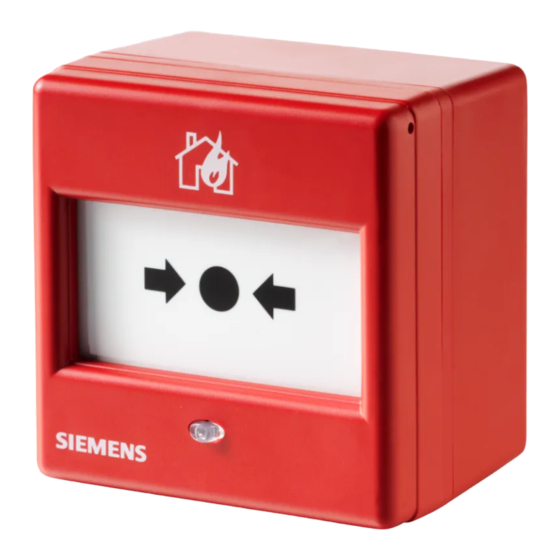
- Page 1 FDM1101-Rx Manual call point collective Technical manual Building Technologies Fire Safety & Security Products...
- Page 2 Technical specifications and availability subject to change without notice. © 2008 Copyright Siemens Switzerland Ltd We reserve all rights in this document and in the subject thereof. By acceptance of the document the recipient acknowledges these rights and undertakes not to publish the document nor the subject thereof in full or in part, nor to make them available to any third party without our...
-
Page 3: Table Of Contents
Table of contents About this document ..................5 Safety......................7 Safety notices....................7 Safety regulations for the method of operation ..........9 Standards and directives complied with............11 Structure and function................12 Overview .......................12 Setup ......................13 3.2.1 Connections ...................13 3.2.2 Indication elements................14 Function......................15 3.3.1 Danger levels .................15 3.3.2 Test mode ..................15 Accessories ....................16... - Page 4 Specifications ....................26 Technical data ....................26 Dimensions....................27 Environmental compatibility................27 Index ......................28 Building Technologies A6V10201150_a_en_-- Fire Safety & Security Products 05.06.2008...
-
Page 5: About This Document
About this document About this document Purpose of the document This document includes all information on the manual call points FDM1101-Rx. Consistent compliance with the instructions guarantees correct and safe use. Target audience This document and the information contained therein are aimed at the target groups defined below. - Page 6 About this document Conventions for text marking ⇨ Result 'Text' Exact wording Technical terms Term Explanation Line termination element (End Of Line) collective Unaddressed detector line Document identification Location Meaning Title page Short name Name in full Document purpose Last page, bottom left-hand Document no.
-
Page 7: Safety
Safety Safety Safety notices The safety notices must be observed in order to protect people and property. The safety notices in this document contain the following elements: Symbol for danger Signal word Nature and origin of the danger Consequences if the danger occurs Measures or prohibitions for danger avoidance Symbol for danger This is the symbol for danger. - Page 8 Safety Signal word The signal word classifies the danger as defined in the following table: Signal word Danger level DANGER DANGER identifies a dangerous situation, which will result directly in death or serious injury if this situation is not avoided. WARNING WARNING identifies a dangerous situation, which may result in death or serious injury if this situation is not avoided.
-
Page 9: Safety Regulations For The Method Of Operation
Safety regulations for the method of operation National standards, regulations and legislation Siemens products are developed and produced in compliance with the relevant European and international safety standards. Should additional country-specific or local safety standards or regulations concerning the project planning, assembly,... - Page 10 Changes to the system layout and products Modifications to the system and to individual products may lead to faults, malfunctioning and safety risks. The written consent of Siemens and the relevant safety bodies must be obtained for modifications or additions.
-
Page 11: Standards And Directives Complied With
We are grateful for suggestions for improvements. Standards and directives complied with A list of the standards and directives complied with is available from your Siemens contact. Building Technologies A6V10201150_a_en_-- Fire Safety &... -
Page 12: Structure And Function
Back box FDMH295-R or Back box FDMH295-S The manual call points FDM1101-Rx are for manually triggering alarms in the case of fire. They consist of a cover and a switching unit. Two back boxes are available as options for surface-mounted feed lines. Back box FDMH295-R does not have pre-drilled holes for surface-mounted feed lines. -
Page 13: Setup
Setup 3.2.1 Connections Manual call points FDM1101-Rx have 4 connection terminals on their rear for the detector line. At the end of the collective detector line, a control-panel specific line termination element (EOL) must be connected with the connection terminal. -
Page 14: Indication Elements
Structure and function 3.2.2 Indication elements Manual call points FDM1101-Rx have a red LED. Only the optical fiber can be seen from the outside. LED in manual call point FDM1101-Rx 1 Red LED for 'Alarm' LED red Meaning Normal operation... -
Page 15: Function
Structure and function Function 3.3.1 Danger levels Manual call points can transmit the following danger levels to the control panel: Danger level Meaning Comment No danger Normal condition Alarm Fire Comment The evaluation of the danger level and the decisions to be taken (e.g. activation of remote transmission) are configured in the control panel. -
Page 16: Accessories
A 'Not in Use' label is enclosed in the delivery of each manual call point. warning label for manual call points that are not in in different languages compatible with manual call points FDM1101-Rx / – FDM1101A-Rx / FDM225 / FDM226 3.4.1.3... -
Page 17: Optional Accessories
FDM1101A-Rx / FDM225-xx / FDM226-xx order no. (10 pcs. per pack): A5Q00013448 3.4.2.2 Protective cover FDMC295 protective cover against unwanted activation compatible with manual call points FDM1101-Rx / FDM1101A-Rx / FDM225-xx / FDM226-xx order no. (10 pcs. per pack): A5Q00013440 3.4.2.3 Plastic inserts FDMP295-x The following plastic inserts can be ordered (5 pcs. -
Page 18: Glass Inserts Fdmg295-X
– order no.: A5Q00013443 FDMG295-S 'Sweden' glass insert – order no.: A5Q00013444 compatible with manual call points FDM1101-Rx / FDM1101A-Rx / FDM225-xx / FDM226-xx 3.4.2.5 Back box FDMH295-R red back box for installation of the manual call point with surface-mounted feed lines... -
Page 19: Back Nut M20 X 1.5
Structure and function 3.4.2.8 Back nut M20 x 1.5 compatible with metal cable gland M20 x 1.5 order no. (100 pcs. per pack): A5Q00004479 3.4.2.9 Connection terminal DBZ1190-AB 3 poles for wire diameters 1 … 2.5 mm to connect the cable shieldings order no. -
Page 20: Project Engineering
Project engineering Project engineering Compatibility Compatible with all fire detection systems with collective/SynoLINE600 signal processing. Refer to 'List of compatibility' (doc. no. 008331) for details. Ranges of application The manual call points are intended for use in places where a fire can be detected by people who can manually trigger an alarm. -
Page 21: Mounting / Installation
Mounting / Installation Mounting / Installation Preparation If you use a back box FDMH295-R, you have to determine the positions of the lead-in openings. If the lead-in openings are on the top or bottom, you must determine them with the drilling jig (package insert). Procedure Installation Note the positive and negative poles! - Page 22 Deactivating the manual call points prevents alarms from being forwarded. The alarm does not take place. Deactivated manual call points must be labeled with the 'NOT IN USE' label! LINE LINE FDM1101-Rx Detector line connection diagram EOL Line termination element (End Of Line) Building Technologies A6V10201150_a_en_-- Fire Safety &...
-
Page 23: Commissioning
Commissioning Commissioning The collective detector line is commissioned on the control panel. The exact procedure is described in the control panel documentation. Building Technologies A6V10201150_a_en_-- Fire Safety & Security Products 05.06.2008... -
Page 24: Maintenance / Repair
Maintenance / Repair Maintenance / Repair Function check The devices are automatically subjected to a performance check during the self- test. Nevertheless, it is necessary to check the devices on site at regular intervals. Recommendation: Check the devices every year. Replace heavily soiled or damaged devices. -
Page 25: Replacing Broken Glass Insert
Maintenance / Repair Replacing broken glass insert The glass insert is covered by a foil layer. This holds the glass splinters together when the glass pane is pushed in, enabling trouble-free removal of the glass. Procedure Removing cover 1. Remove the cover of the manual call point using the key (movements A and B). 2. -
Page 26: Specifications
1 GHz … 2 GHz 10 V/m Mechanical data Dimensions (L x W x H): FDM1101-Rx 87 x 87 x 20 mm FDM1101-Rx with back box 87 x 87 x 53 mm FDMH295-R / FDMH295-S Weight: FDM1101-Rx 0.097 kg Back box FDMH295-R / FDMH295-S 0.057 kg... -
Page 27: Dimensions
ISO9001 ISO9004 CE conformity mark Dimensions 35,5 Dimensional drawings for FDM1101-Rx and back box FDMH295-R / FDMH295-S Environmental compatibility Electronic components and synthetic materials can be separated. The plastic parts are marked and can be disposed of correspondingly. Building Technologies A6V10201150_a_en_-- Fire Safety &... -
Page 28: Index
Index Index Alarm indicator Line termination element Red LED, 14 EOL, 13 Back box Manual call point Surface-mounted feed lines, 12 Test mode, 15 Broken glass insert Replacing glass insert, 26 Red LED Alarm indicator, 14 Collective Remove Communication, 12 Cover, 22 Communication Replacing... - Page 29 Index Building Technologies A6V10201150_a_en_-- Fire Safety & Security Products 05.06.2008...
- Page 30 Issued by © 2008 Copyright Siemens Switzerland Ltd Siemens Switzerland Ltd Technical specifications and availability subject to change without notice. Building Technologies Division International Headquarter Gubelstrasse 22 CH-6301 Zug Tel. +41 41-724 24 24 Fax +41 41-723 35 22 www.siemens.com/buildingtechnologies Document no.