
Related Manuals for HP Synergy 480 Gen10


Summary of Contents for HP Synergy 480 Gen10
- Page 1 HPE Synergy 480 Gen10 Compute Module User Guide HPE Synergy 480 Gen10 Compute Module User Guide Part Number: 30-AAD7A7A0-008 Published: June 2021 Edition: 8...
- Page 2 HPE Synergy 480 Gen10 Compute Module User Guide HPE Synergy 480 Gen10 Compute Module User Guide Abstract Abstract This document is for the person who installs, administers, and troubleshoots the HPE Synergy system. Hewlett Packard Enterprise assumes you are qualified in the servicing of computer equipment and trained in recognizing hazards in products with hazardous energy levels.
-
Page 3: Table Of Contents
Table of contents Table of contents 1 Component identification 1.1 Front panel components 1.1.1 Serial label pull tab information 1.2 Front panel LEDs and buttons 1.3 Drive numbering 1.4 Smart Carrier (SC) drive LED definitions 1.5 SFF flash adapter components and LED definitions 1.6 Smart Carrier NVMe (SCN) drive LED definitions 1.7 System board components 1.7.1 System maintenance switch... - Page 4 4.2 Installing SAS, SATA, or solid state drives 4.3 Installing the SFF flash adapter option 4.4 Installing the M.2 SSD flash drive and adapter board 4.5 Installing the controller option 4.6 Installing mezzanine card options 4.7 Installing the P416ie-m Controller mezzanine option 4.8 HPE Smart Storage Battery 4.9 HPE Smart Storage Hybrid Capacitor 4.9.1 Minimum firmware versions...
- Page 5 5.2 Energy pack option cabling 5.3 P416ie-m Smart Array Controller cabling 6 Removing and replacing the system battery 7 Electrostatic discharge 7.1 Preventing electrostatic discharge 7.2 Grounding methods to prevent electrostatic discharge 8 Specifications 8.1 Compute module environmental specifications 8.2 Compute module physical specifications 9 HPE Synergy documentation resources 9.1 HPE Synergy firmware update resources 10 HPE Synergy documentation map...
-
Page 6: Component Identification
Component identification Component identification Component identification... -
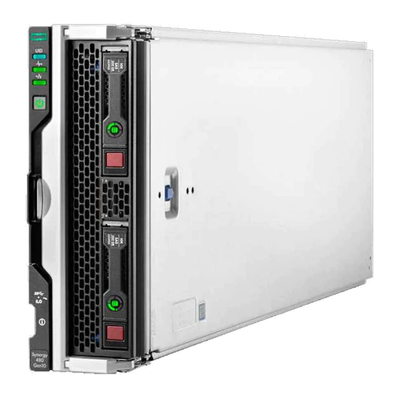
Page 7: Front Panel Components
Front panel components Front panel components Item Item Description Description Drive bay 1 Drive bay 2 External USB iLO Service Port (169.254.1.2) - located behind the Serial label pull tab External USB 3.0 connector (located behind the Serial label pull tab) Compute module handle release latch Compute module handle If uFF drives (the SFF Flash Storage Adapter) are installed in the drive bays, the drive bay numbering is different. -
Page 8: Serial Label Pull Tab Information
Serial label pull tab information Serial label pull tab information The serial label pull tab is on the front panel of the compute module. To locate the serial label pull tab, see Front panel components. The serial label pull tab provides the following information: Product serial number HPE iLO information Serial label pull tab information... -
Page 9: Front Panel Leds And Buttons
Front panel LEDs and buttons Front panel LEDs and buttons Item Item Description Description Status Status UID LED Solid blue = Activated Flashing blue (1 Hz/cycle per sec) = Remote management or firmware upgrade in progress Off = Deactivated Health status LED Solid green = Normal Flashing green (1 Hz/cycle per sec) = iLO is rebooting. - Page 10 Front panel LEDs and buttons...
-
Page 11: Drive Numbering
Drive numbering Drive numbering Depending on the configuration, this compute module can support hard drives, SSDs, NVMe drives, and uFF drives (supported in dual SFF flash adapters) in the drive bays. Depending on the device installed, the bay number might be different. Item Item Hard drive/SSD bay numbering... -
Page 12: Smart Carrier (Sc) Drive Led Definitions
Smart Carrier (SC) drive LED definitions Smart Carrier (SC) drive LED definitions Item Item Status Status Definition Definition Locate Solid blue The drive is being identified by a host application. Flashing blue The drive carrier firmware is being updated or requires an update. Activity Rotating green Drive activity... -
Page 13: Sff Flash Adapter Components And Led Definitions
SFF flash adapter components and LED definitions SFF flash adapter components and LED definitions Item Item Component Component Description Description Locate Off—Normal Solid blue—The drive is being identified by a host application. Flashing blue—The drive firmware is being updated or requires an update. -
Page 14: Smart Carrier Nvme (Scn) Drive Led Definitions
Smart Carrier NVMe (SCN) drive LED definitions Smart Carrier NVMe (SCN) drive LED definitions The NVMe drive is a PCIe bus device. A device attached to a PCIe bus cannot be removed without allowing the device and bus to complete and cease the signal/traffic flow. CAUTION: Do not remove an NVMe drive from the drive bay while the Do not remove LED is flashing. - Page 15 Smart Carrier NVMe (SCN) drive LED definitions...
-
Page 16: System Board Components
System board components System board components Item Item Description Description System battery Internal USB 3.0 connector Processor 1 DIMM slots (12) Processor 2 DIMM slots (12) Energy pack option connector Mezzanine connectors (M1, M2, and M3) Management/power connector System maintenance switch External USB iLO Service Port (169.254.1.2) - located behind the Serial label pull tab External USB 3.0 connector (located behind the Serial label pull tab) MicroSD connector... -
Page 17: System Maintenance Switch
System maintenance switch System maintenance switch Position Position Default Default Function Function Off = HPE iLO security is enabled. On = HPE iLO security is disabled. Reserved Reserved Reserved Off = Power-on password is enabled. On = Power-on password is disabled. Off = No function On = Reset configuration Reserved... -
Page 18: Processor, Heatsink, And Socket Components
Processor, heatsink, and socket components Processor, heatsink, and socket components Item Item Description Description Heatsink nuts Processor carrier Pin 1 indicator Heatsink guide/keying feature Alignment post Heatsink keying frame Symbol also on the processor and frame. Processor, heatsink, and socket components... -
Page 19: Mezzanine Connector Definitions
Hewlett Packard Enterprise recommends that you install P416ie-m on mezzanine 1. * When an NVIDIA Tesla M6 GPU FIO Adapter for HPE Synergy 480 Gen10 compute module is installed in mezzanine connector 1, mezzanine connector 2 is not available for additional mezzanine cards. -
Page 20: Dimm Slot Locations
DIMM slot locations DIMM slot locations DIMM slots are numbered sequentially (1 through 12) for each processor. For more information on DIMM population rules, see the HPE website (https://www.hpe.com/docs/memory-population-rules https://www.hpe.com/docs/memory-population-rules). The slots indicate the slot order within each channel: White—First slot of a channel Black—Second slot of a channel First socket channel Second socket channel... -
Page 21: Dimm Label Identification
DIMM label identification DIMM label identification To determine DIMM characteristics, see the label attached to the DIMM. The information in this section helps you to use the label to locate specific information about the DIMM. Item Item Description Description Example Example Capacity 8 GB... - Page 22 Item Item Description Description Example Example CAS latency P = CAS 15-15-15 T = CAS 17-17-17 U = CAS 20-18-18 V = CAS 19-19-19 (for RDIMM, LRDIMM) V = CAS 22-19-19 (for 3DS TSV LRDIMM) Y = CAS 21-21-21 (for RDIMM, LRDIMM) Y = CAS 24-21-21 (for 3DS TSV LRDIMM) DIMM type R = RDIMM (registered)
-
Page 23: Nvdimm Identification
NVDIMM identification NVDIMM identification NVDIMMs are supported only when first-generation Intel Xeon Scalable processors are installed on the compute module. NVDIMM boards are blue instead of green. This change to the color makes it easier to distinguish NVDIMMs from DIMMs. To determine NVDIMM characteristics, see the full product description as shown in the following example: Item Item... -
Page 24: Nvdimm 2D Data Matrix Barcode
NVDIMM 2D Data Matrix barcode NVDIMM 2D Data Matrix barcode The 2D Data Matrix barcode is on the right side of the NVDIMM label and can be scanned by a cell phone or other device. When scanned, the following information from the label can be copied to your cell phone or device: (P) is the module part number. -
Page 25: Nvdimm Led Identification
NVDIMM LED identification NVDIMM LED identification Item LED description Item LED description LED color LED color Power LED Green Function LED Blue NVDIMM LED identification... -
Page 26: Nvdimm-N Led Combinations
NVDIMM-N LED combinations NVDIMM-N LED combinations State State Definition Definition NVDIMM-N Power LED (green) NVDIMM-N Power LED (green) NVDIMM-N Function LED (blue) NVDIMM-N Function LED (blue) AC power is on (12V rail) but the NVM controller is not working or not ready. AC power is on (12V rail) and the NVM controller is ready. -
Page 27: Nvdimm Function Led Patterns
NVDIMM Function LED patterns NVDIMM Function LED patterns For the purpose of this table, the NVDIMM-N LED operates as follows: Solid indicates that the LED remains in the on state. Flashing indicates that the LED is on for 2 seconds and off for 1 second. Fast-flashing indicates that the LED is on for 300 ms and off for 300 ms. -
Page 28: Intel Optane Persistent Memory 100 Series For Hpe Label Identification
Intel Optane persistent memory 100 series Intel Optane persistent memory 100 series for HPE for HPE label identification label identification Item Item Description Description Example Example Unique ID number 8089-A2-1802-1234567 Model number NMA1XBD512G2S Capacity 128 GB 256 GB 512 GB QR code Includes part number and serial number For more information about product features, specifications, options, configurations, and compatibility, see the product QuickSpecs on... -
Page 29: Enterprise Midline Usb
Enterprise Midline USB Enterprise Midline USB Item Item Description Description microSD card slot microSD1 card microSD2 card Enterprise Midline USB... -
Page 30: Leds
LEDs LEDs Item Item Description Description Status Status Power LED Green: Device is on and at least one microSD card is functioning. Red: Both microSD cards have failed. SD2 LED On: microSD card has failed. Off: microSD card is healthy. SD1 LED On: microSD card has failed. -
Page 31: Component And Led Identification For Hpe Synergy Hardware
Component and LED identification for HPE Synergy Component and LED identification for HPE Synergy hardware hardware For more information about component and LED identification for HPE Synergy components, see the product-specific maintenance and service guide or the HPE Synergy 12000 Frame Setup and Installation Guide HPE Synergy 12000 Frame Setup and Installation Guide in the Hewlett Packard Enterprise Support Center. -
Page 32: Operations
Operations Operations Operations... -
Page 33: Powering Up The Compute Module
Powering up the compute module Powering up the compute module To power up the compute module, press the Power On/Standby button after the power button LED has turned amber. Powering up the compute module... -
Page 34: Powering Down The Compute Module
Powering down the compute module Powering down the compute module Before powering down the compute module for any upgrade or maintenance procedures, perform a backup of the system and all data. Then, shut down, as appropriate, applications and operating systems. A successful shutdown is indicated by the system power LED displaying amber. -
Page 35: Removing The Drive Blank
Removing the drive blank Removing the drive blank Remove the component as indicated. CAUTION: To prevent improper cooling and thermal damage, do not operate the compute module unless all bays are CAUTION: populated with either a component or a blank. Removing the drive blank... -
Page 36: Removing The Compute Module
Removing the compute module Removing the compute module Prerequisites Prerequisites CAUTION: CAUTION: Before removing the compute module, verify that the compute module is in standby mode. In standby mode, the system power LED is off or solid amber. Also, verify that the UID LED is off or solid blue. Procedure Procedure 1. -
Page 37: Removing The Compute Module End Cap
Removing the compute module end cap Removing the compute module end cap Procedure Procedure 1. Place the compute module on a flat, level work surface. 2. Remove the compute module end cap. Removing the compute module end cap... -
Page 38: Removing The Access Panel
Removing the access panel Removing the access panel Procedure Procedure 1. Power down the compute module. 2. Remove the compute module. 3. Place the compute module on a flat, level work surface. 4. Press the access panel release button. 5. Slide the access panel towards the rear of the compute module, and then lift up to remove the panel. Removing the access panel... -
Page 39: Removing The Dimm Baffle
Removing the DIMM baffle Removing the DIMM baffle Procedure Procedure 1. Power down the compute module. 2. Remove the compute module. 3. Place the compute module on a flat, level work surface. 4. Remove the access panel . IMPORTANT: When removing the right DIMM baffle, leave the Smart Storage Battery installed on the baffle. IMPORTANT: Use the blue pull tab to disconnect the Smart Storage Battery cable from the system board. -
Page 40: Removing The Front Panel/Drive Cage Assembly
Removing the front panel/drive cage assembly Removing the front panel/drive cage assembly Procedure Procedure 1. Power down the compute module. 2. Remove the compute module. 3. Place the compute module on a flat, level work surface. 4. Remove the access panel . 5. -
Page 41: Installing The Compute Module End Cap
Installing the compute module end cap Installing the compute module end cap Procedure Procedure 1. Place the compute module on a flat, level work surface. 2. Install the compute module end cap. Installing the compute module end cap... -
Page 42: Installing The Access Panel
Installing the access panel Installing the access panel Procedure Procedure 1. Place the access panel on top of the compute module. 2. Slide the access panel forward until it clicks into place. Installing the access panel... -
Page 43: Installing The Dimm Baffles
Installing the DIMM baffles Installing the DIMM baffles Procedure Procedure 1. Install the DIMM baffles. 2. Install the access panel . 3. Install the compute module. Installing the DIMM baffles... -
Page 44: Installing The Front Panel/Drive Cage Assembly
Installing the front panel/drive cage assembly Installing the front panel/drive cage assembly Procedure Procedure 1. Install the front panel/drive cage assembly. 2. Install all drives . 3. Install the access panel . 4. Install the compute module. Installing the front panel/drive cage assembly... -
Page 45: Setup
Setup Setup Setup... -
Page 46: Installation Overview
Installation overview Installation overview Use this section and the following procedure to install the HPE Synergy 480 Gen10 Compute Module in a frame for the first time. Procedure Procedure 1. Install supported options for the compute module. 2. Install the compute module. -
Page 47: Installing The Compute Module
Installing the compute module Installing the compute module Procedure Procedure 1. Verify that the device bay is configured for a half-height compute module. For more information, see the setup and installation guide for the frame on the Hewlett Packard Enterprise website Hewlett Packard Enterprise website . - Page 48 CAUTION: CAUTION: Before removing the compute module, be sure to verify that the compute module is in standby mode by observing that the system power LED is amber. Also, verify that the UID LED is not flashing blue. Installing the compute module...
-
Page 49: Completing The Configuration
Completing the configuration Completing the configuration When a compute module is added to an existing configuration, HPE OneView automatically detects the new hardware. HPE OneView is hosted on the HPE Synergy Composer appliance installed in the HPE Synergy 12000 Frame. You can use HPE OneView to comprehensively manage an HPE Synergy system throughout the hardware life cycle. -
Page 50: Hardware Options Installation
Hardware options installation This chapter provides detailed instructions on how to install hardware options. For more information on supported options, see the product QuickSpecs on the HPE Synergy 480 Gen10 Compute Module website at: http://www.hpe.com/info/synergy-docs To view the warranty for your server and supported options, see Warranty information. -
Page 51: Introduction
Introduction Introduction If more than one option is being installed, read the installation instructions for all the hardware options and identify similar steps to streamline the installation process. WARNING: To reduce the risk of personal injury from hot surfaces, allow the drives and the WARNING: internal system components to cool before touching them. -
Page 52: Installing Sas, Sata, Or Solid State Drives
Installing SAS, SATA, or solid state drives Installing SAS, SATA, or solid state drives Procedure Procedure 1. Remove the drive blank. 2. Prepare the drive. 3. Install the drive. 4. Determine the status of the drive from the drive LED definitions. Installing SAS, SATA, or solid state drives... -
Page 53: Installing The Sff Flash Adapter Option
Installing the SFF flash adapter option Installing the SFF flash adapter option CAUTION: To prevent improper cooling and thermal damage, do not operate the compute module or the enclosure CAUTION: unless all drive and device bays are populated with either a component or a blank. Prequisites Prequisites The SFF flash adapter option is supported when any of the following components are installed:... -
Page 54: Installing The M.2 Ssd Flash Drive And Adapter Board
Installing the M.2 SSD flash drive and adapter board Installing the M.2 SSD flash drive and adapter board Prerequisites Prerequisites To complete this procedure, you need a No. 1 Phillips screwdriver. Procedure Procedure 1. Power down the compute module. 2. Remove the compute module. 3. - Page 55 b. Press down where indicated on the adapter board to lower it down onto the system board connector until it is fully engaged. The adapter board clicks into place when fully engaged. Installing the M.2 SSD flash drive and adapter board...
-
Page 56: Installing The Controller Option
Installing the controller option Installing the controller option For more information about supported options, see the product QuickSpecs on the Hewlett Packard Enterprise website Hewlett Packard Enterprise website . CAUTION: Hewlett Packard Enterprise recommends performing a complete backup of all compute module data before CAUTION: installing or removing a controller or adapter. -
Page 57: Installing Mezzanine Card Options
Installing mezzanine card options Installing mezzanine card options Mezzanine options are classified as Type C and Type D mezzanine cards. The type of mezzanine card determines where the card can be installed in the compute module. Some mezzanine cards require an interconnect module to be installed in the associated ICM bay in the rear of the frame. -
Page 58: Installing The P416Ie-M Controller Mezzanine Option
Installing the P416ie-m Controller mezzanine option Installing the P416ie-m Controller mezzanine option IMPORTANT: IMPORTANT: For more information about the association between the mezzanine bay and the interconnect bays, see the HPE Synergy 12000 Frame Setup and Installation Guide (https://www.hpe.com/info/synergy-docs https://www.hpe.com/info/synergy-docs). Where you install the mezzanine card determines where you need to install the interconnect modules. - Page 59 9. Install the access panel . 10. Install the compute module. 11. Power up the compute module. More information More information Mezzanine connector definitions Installing the P416ie-m Controller mezzanine option...
-
Page 60: Hpe Smart Storage Battery
HPE Smart Storage Battery HPE Smart Storage Battery The HPE Smart Storage Battery supports the following devices: HPE Smart Array SR controllers A single 96W battery can support up to 24 devices. After the battery is installed, it might take up to two hours to charge. Controller features requiring backup power are not re-enabled until the battery is capable of supporting the backup power. -
Page 61: Hpe Smart Storage Hybrid Capacitor
HPE Smart Storage Hybrid Capacitor HPE Smart Storage Hybrid Capacitor The HPE Smart Storage Hybrid Capacitor supports the following devices: HPE Smart Array SR controllers The capacitor pack can support up to three devices. This server supports the HPE Smart Storage Hybrid Capacitor with the 260mm cable. Before installing the HPE Smart Storage Hybrid Capacitor, verify that the system BIOS meets the minimum firmware requirements to support the capacitor pack. -
Page 62: Minimum Firmware Versions
Minimum firmware versions Minimum firmware versions Product Product Minimum firmware version Minimum firmware version HPE Synergy 480 Gen10 Compute Module system ROM 2.00 HPE Smart Array SR controllers 1.90 Minimum firmware versions... -
Page 63: Installing The Energy Pack Option
Installing the energy pack option Installing the energy pack option Hewlett Packard Enterprise now offers two options as a centralized backup power source for backing up write cache content on Smart Array controllers if there is an unplanned server power loss. HPE Smart Storage Battery HPE Smart Storage Hybrid Capacitor IMPORTANT:... - Page 64 7. Install the left DIMM baffle . 8. Connect the left energy pack to the system board. To locate the energy pack option connector, see " System board components." 9. Install the access panel . 10. Install the compute module. 11.
-
Page 65: Memory Options
Memory options Memory options IMPORTANT: This compute module does not support mixing LRDIMMs and RDIMMs. Attempting to mix any IMPORTANT: combination of these DIMMs can cause the server to halt during BIOS initialization. All memory installed in the compute module must be of the same type. Memory options... -
Page 66: Dimm And Nvdimm Population Information
DIMM and NVDIMM population information DIMM and NVDIMM population information For specific DIMM and NVDIMM population information, see the DIMM population guidelines on the Hewlett Packard Enterprise website (https://www.hpe.com/docs/memory-population-rules https://www.hpe.com/docs/memory-population-rules). DIMM and NVDIMM population information... -
Page 67: Dimm-Processor Compatibility
DIMM-processor compatibility DIMM-processor compatibility The installed processor determines the type of DIMM that is supported in the compute module: First-generation Intel Xeon Scalable processors support DDR4-2666 DIMMs. Second-generation Intel Xeon Scalable processors support DDR4-2933 DIMMs. Mixing DIMM types is not supported. Install only the supported DDR4-2666 or DDR4-2933 DIMMs in the compute module. DIMM-processor compatibility... -
Page 68: Hpe Smartmemory Speed Information
HPE SmartMemory speed information HPE SmartMemory speed information For more information about memory speed information, see the Hewlett Packard Enterprise website (https://www.hpe.com/docs/memory-speed-table https://www.hpe.com/docs/memory-speed-table). HPE SmartMemory speed information... -
Page 69: Installing A Dimm
Installing a DIMM Installing a DIMM The server supports up to 24 DIMMs. Prerequisites Prerequisites Before installing this option, be sure you have the following: The components included with the hardware option kit For more information on specific options, see the compute module QuickSpecs on the Hewlett Packard Enterprise Hewlett Packard Enterprise website website. -
Page 70: Hpe 16Gb Nvdimm Option
HPE 16GB NVDIMM option HPE 16GB NVDIMM option HPE NVDIMMs are flash-backed NVDIMMs used as fast storage and are designed to eliminate smaller storage bottlenecks. The HPE 16GB NVDIMM for HPE ProLiant Gen10 servers is ideal for smaller database storage bottlenecks, write caching tiers, and any workload constrained by storage bottlenecks. -
Page 71: Server Requirements For Nvdimm Support
Server requirements for NVDIMM support Server requirements for NVDIMM support Before installing an HPE 16GB NVDIMM in a compute module, make sure that the following components and software are available: A supported HPE server using Intel Xeon Scalable Processors: For more information, see the NVDIMM QuickSpecs on the Hewlett Packard Enterprise website (https://www.hpe.com/info/qs https://www.hpe.com/info/qs). -
Page 72: Installing An Nvdimm
Installing an NVDIMM Installing an NVDIMM CAUTION: CAUTION: To avoid damage to the hard drives, memory, and other system components, the air baffle, drive blanks, and access panel must be installed when the server is powered up. CAUTION: CAUTION: To avoid damage to the hard drives, memory, and other system components, be sure to install the correct DIMM baffles for your server model. - Page 73 8. Install and connect the HPE Smart Storage Battery , if it is not already installed. 9. Install any components removed to access the DIMM slots and the HPE Smart Storage Battery. 10. Install the access panel . 11. Install the compute module. 12.
-
Page 74: Configuring The Compute Module For Nvdimms
Configuring the compute module Configuring the compute module for NVDIMMs for NVDIMMs After installing NVDIMMs, configure the compute module for NVDIMMs. For information on configuring settings for NVDIMMs, see the HPE 16GB NVDIMM User Guide on the Hewlett Packard Enterprise website ( https://www.hpe.com/info/nvdimm-docs https://www.hpe.com/info/nvdimm-docs). -
Page 75: Nvdimm Sanitization
NVDIMM sanitization NVDIMM sanitization Media sanitization is defined by NIST SP800-88 Guidelines for Media Sanitization (Rev 1, Dec 2014) as "a general term referring to the actions taken to render data written on media unrecoverable by both ordinary and extraordinary means." The specification defines the following levels: Clear: Overwrite user-addressable storage space using standard write commands;... -
Page 76: Nvdimm Relocation Guidelines
NVDIMM relocation guidelines NVDIMM relocation guidelines Requirements for relocating NVDIMMs or a set of NVDIMMs when the data must be preserved Requirements for relocating NVDIMMs or a set of NVDIMMs when the data must be preserved The destination compute module hardware must match the original compute module hardware configuration. All System Utilities settings in the destination compute module must match the original System Utilities settings in the original compute module. -
Page 77: Intel Optane Persistent Memory 100 Series For Hpe
Intel Optane persistent memory 100 series Intel Optane persistent memory 100 series for HPE for HPE Intel Optane persistent memory 100 series for HPE offers the flexibility to deploy as dense memory (Memory mode) or fast storage (App Direct mode) and enables per-socket memory capacity of up to 3.0 TB. Persistent memory modules, together with traditional volatile DRAM DIMMs, provide fast, high-capacity, cost-effective memory and storage to transform big data workloads and analytics by enabling data to be stored, moved, and processed quickly. -
Page 78: Persistent Memory Module-Processor Compatibility
Persistent memory module-processor compatibility Persistent memory module -processor compatibility Intel Optane persistent memory 100 series for HPE is supported only in servers with second-generation Intel Xeon Scalable processors installed. Persistent memory module-processor compatibility... -
Page 79: Persistent Memory Module Population Information
Persistent memory module population information Persistent memory module population information For specific population and configuration information, see the memory population guidelines on the Hewlett Packard Enterprise website (https://www.hpe.com/docs/memory-population-rules https://www.hpe.com/docs/memory-population-rules). Persistent memory module population information... -
Page 80: System Requirements For Persistent Memory Module Support
System requirements for persistent memory module System requirements for persistent memory module support support IMPORTANT: IMPORTANT: Hewlett Packard Enterprise recommends that you implement best-practice configurations such as clustered configurations for high availability (HA). Before installing persistent memory modules, make sure that the following components and software are available: A supported HPE ProLiant Gen10 server or Synergy compute module using second-generation Intel Xeon Scalable processors. -
Page 81: Installing Persistent Memory Modules
Installing persistent memory modules Installing persistent memory modules IMPORTANT: IMPORTANT: Hewlett Packard Enterprise recommends that you implement best-practice configurations such as clustered configurations for high availability (HA). Use this procedure only for new persistent memory module installations. If you are migrating this persistent memory module from another compute module, see the Intel Optane persistent memory 100 series for HPE User Guide on the Hewlett Packard Enterprise website (https://www.hpe.com/info/persistentmemory-docs https://www.hpe.com/info/persistentmemory-docs). -
Page 82: Configuring The Compute Module For Intel Optane Persistent Memory 100 Series For Hpe
8. Install any components removed to access the DIMM slots. 9. Install the access panel . 10. Slide or install the compute module into the frame. 11. If removed, reconnect all power cables. 12. Power up the compute module. 13. Configure the server for Intel Optane persistent memory for HPE. More information More information Persistent memory module population information... - Page 83 Configuring the compute module Configuring the compute module for for Intel Optane persistent memory Intel Optane persistent memory 100 series 100 series for HPE for HPE After installing persistent memory modules, configure the compute module for Intel Optane persistent memory for HPE. IMPORTANT: IMPORTANT: Always follow recommendations from your software application provider for high-availability best practices to ensure...
-
Page 84: Persistent Memory Module Relocation Guidelines
Persistent memory module relocation guidelines Persistent memory module relocation guidelines Observe the relocation guidelines when doing the following: When relocating persistent memory modules to another DIMM slot on the compute module. When relocating persistent memory modules to another compute module. When reinstalling persistent memory modules after replacing the compute module system board. - Page 85 Review and configure the system settings for Intel Optane persistent memory for HPE. For more information, see the Intel Optane persistent memory 100 series for HPE User Guide on the Hewlett Packard Enterprise website (https://www.hpe.com/info/persistentmemory-docs https://www.hpe.com/info/persistentmemory-docs). Persistent memory module relocation guidelines...
-
Page 86: Migrating A Persistent Memory Module
Migrating a persistent memory module Migrating a persistent memory module IMPORTANT: IMPORTANT: When data must be preserved, Hewlett Packard Enterprise strongly recommends that you perform a manual backup of all user data on the persistent memory modules before changing the goal configuration or performing relocation procedures. -
Page 87: Installing The Processor Heatsink Option
Installing the processor heatsink option Installing the processor heatsink option The server supports installation of 1–4 processors. IMPORTANT: IMPORTANT: Existing HPE ProLiant and HPE Synergy Gen10 server products containing first-generation Intel Xeon Scalable processors may not be upgraded to second-generation Intel Xeon Scalable processors at this time. For more information, see the product QuickSpecs on the Hewlett Packard Enterprise website (https://www.hpe.com/info/qs https://www.hpe.com/info/qs). - Page 88 8. Align the processor heatsink assembly with the alignment pins and gently lower it down until it sits evenly on the socket. The heatsink alignment pins are keyed. The processor will only install one way. A standard heatsink is shown. Your heatsink might look different. 9.
- Page 89 10. Install all DIMM baffles . 11. Install the access panel . 12. Install supported hardware options for the compute module. Installing the processor heatsink option...
-
Page 90: Hpe Trusted Platform Module 2.0 Gen10 Option
HPE Trusted Platform Module 2.0 Gen10 option HPE Trusted Platform Module 2.0 Gen10 option HPE Trusted Platform Module 2.0 Gen10 option... -
Page 91: Overview
Overview Overview Use these instructions to install and enable an HPE TPM 2.0 Gen10 Kit in a supported compute module. This option is not supported on a Gen9 and earlier compute module. This procedure includes three sections: 1. Installing the Trusted Platform Module board. 2. -
Page 92: Hpe Trusted Platform Module 2.0 Guidelines
HPE Trusted Platform Module 2.0 guidelines Trusted Platform Module 2.0 guidelines CAUTION: Always observe the guidelines in this document. Failure to follow these guidelines can cause hardware CAUTION: damage or halt data access. Hewlett Packard Enterprise SPECIAL REMINDER: Hewlett Packard Enterprise SPECIAL REMINDER: Before enabling TPM functionality on this system, you must ensure that your intended use of TPM complies with relevant local laws, regulations and policies, and approvals or licenses must be obtained if applicable. -
Page 93: Installing And Enabling The Hpe Tpm 2.0 Gen10 Option
Installing and enabling the HPE TPM 2.0 Gen10 option Installing and enabling the HPE TPM 2.0 Gen10 option Installing and enabling the HPE TPM 2.0 Gen10 option... -
Page 94: Installing The Trusted Platform Module Board
Installing the Trusted Platform Module board Installing the Trusted Platform Module board Installing the Trusted Platform Module board... -
Page 95: Preparing The Compute Module For Installation
Preparing the compute module Preparing the compute module for installation for installation Procedure Procedure 1. Observe the following warnings: WARNING: The front panel Power On/Standby button does not shut off system power. WARNING: Portions of the power supply and some internal circuitry remain active until AC power is removed. -
Page 96: Installing The Tpm Board And Cover
Installing the TPM board and cover Installing the TPM board and cover Procedure Procedure 1. Observe the following alerts: CAUTION: If the TPM is removed from the original compute module and powered up on a different compute module, CAUTION: data stored in the TPM including keys will be erased. CAUTION: The TPM is keyed to install only in the orientation shown. - Page 97 4. Proceed to Preparing the compute module for operation. Installing the TPM board and cover...
-
Page 98: Preparing The Compute Module For Operation
Preparing the compute module Preparing the compute module for operation for operation Procedure Procedure 1. Install any options or cables previously removed to access the TPM connector. 2. Install the access panel. 3. Do one of the following: Slide or install the server into the rack. Install the compute module into the frame. -
Page 99: Enabling The Trusted Platform Module
Enabling the Trusted Platform Module Enabling the Trusted Platform Module When enabling the Trusted Platform module, observe the following guidelines: By default, the Trusted Platform Module is enabled as TPM 2.0 when the compute module is powered on after installing it. In UEFI Boot Mode, the Trusted Platform Module can be configured to operate as TPM 2.0 (default) or TPM 1.2. -
Page 100: Enabling The Trusted Platform Module As Tpm 2.0
Enabling the Trusted Platform Module as TPM 2.0 Enabling the Trusted Platform Module as TPM 2.0 Procedure Procedure 1. During the compute module startup sequence, press the F9 key to access System Utilities. 2. From the System Utilities screen, select System Configuration > BIOS/Platform Configuration (RBSU) > Server Security > Trusted Platform Module options. - Page 101 Enabling the Trusted Platform Module as TPM 1.2 Enabling the Trusted Platform Module as TPM 1.2 Procedure Procedure 1. During the compute module startup sequence, press the F9 key to access System Utilities. 2. From the System Utilities screen select System Configuration > BIOS/Platform Configuration (RBSU) > Server Security > Trusted Platform Module options.
-
Page 102: Retaining The Bitlocker Recovery Key/Password
Retaining the BitLocker recovery key/password Retaining the BitLocker recovery key/password The recovery key/password is generated during BitLocker setup, and can be saved and printed after BitLocker is enabled. When using BitLocker, always retain the recovery key/password. The recovery key/password is required to enter Recovery Mode after BitLocker detects a possible compromise of system integrity. -
Page 103: Cabling
Cabling Cabling Cabling... -
Page 104: Cabling Resources
Cabling resources Cabling resources Cabling configurations and requirements vary depending on the product and installed options. For more information about product features, specifications, options, configurations, and compatibility, see the product QuickSpecs on the Hewlett Packard Enterprise website (https://www.hpe.com/info/qs https://www.hpe.com/info/qs). Cabling resources... -
Page 105: Energy Pack Option Cabling
Energy pack option cabling Energy pack option cabling Energy pack option cabling... -
Page 106: P416Ie-M Smart Array Controller Cabling
P416ie-m Smart Array Controller cabling P416ie-m Smart Array Controller cabling Port 3i connector Mezzanine option card in mezzanine slot 1 SAS cable connector P416ie-m Smart Array Controller cabling... -
Page 107: Removing And Replacing The System Battery
Removing and replacing the system battery Removing and replacing the system battery The system battery provides power to the real-time clock. Under normal use, battery life is 5 to 10 years. If the compute module no longer automatically displays the correct date and time, then the system battery needs to be replaced. WARNING: The computer contains an internal lithium manganese dioxide, a vanadium WARNING: pentoxide, or an alkaline battery pack. -
Page 108: Electrostatic Discharge
Electrostatic discharge Electrostatic discharge Electrostatic discharge... -
Page 109: Preventing Electrostatic Discharge
Preventing electrostatic discharge Preventing electrostatic discharge To prevent damaging the system, be aware of the precautions you must follow when setting up the system or handling parts. A discharge of static electricity from a finger or other conductor may damage system boards or other static-sensitive devices. This type of damage may reduce the life expectancy of the device. -
Page 110: Grounding Methods To Prevent Electrostatic Discharge
Grounding methods to prevent electrostatic discharge Grounding methods to prevent electrostatic discharge Several methods are used for grounding. Use one or more of the following methods when handling or installing electrostatic-sensitive parts: Use a wrist strap connected by a ground cord to a grounded workstation or computer chassis. Wrist straps are flexible straps with a minimum of 1 megohm ±10 percent resistance in the ground cords. -
Page 111: Specifications
Specifications Specifications Specifications... -
Page 112: Compute Module Environmental Specifications
Compute module environmental specifications Compute module environmental specifications Specification Specification Value Value Temperature range* Temperature range* — — Operating 10°C to 35°C (50°F to 95°F) Non-operating -30°C to 60°C (-22°F to 140°F) Relative humidity Relative humidity — — (noncondensing)** (noncondensing)** Operating 8% to 90% @ -12 °C - 24°C (10.4°F - 75.2°F) Non-operating... -
Page 113: Compute Module Physical Specifications
Compute module physical specifications Compute module physical specifications The following details physical specifications for the HPE Synergy 480 Gen10 compute module. Specification Specification Value Value Height 63.60 mm (2.50 in) Depth 606.50 mm (23.88 in) Width 214.00 mm (8.43 in) Weight (maximum) 8.16 kg (18.00 lb) -
Page 114: Hpe Synergy Documentation Resources
HPE Synergy documentation resources HPE Synergy documentation resources The Hewlett Packard Enterprise Support Center provides a comprehensive, one stop location for all HPE Synergy documentation, including installation instructions, maintenance and service guides, best practices, and links to additional resources. It supports filtering to improve findability. -
Page 115: Hpe Synergy Firmware Update Resources
HPE Synergy firmware update resources HPE Synergy firmware update resources The HPE Synergy Software Release Information site ( https://www.hpe.com/info/synergy-sw-release-information https://www.hpe.com/info/synergy-sw-release-information) provides an interactive resource for firmware update information. HPE Synergy firmware update resources are also available within HPE OneView. HPE Synergy Software Release HPE Synergy Software Release Provides: Provides:... -
Page 116: Hpe Synergy Documentation Map
HPE Synergy documentation map HPE Synergy documentation map The Hewlett Packard Enterprise Support Center provides access to the HPE Synergy documentation. For quick links to different HPE Synergy document types, see the following website: http://www.hpe.com/info/synergy-docs http://www.hpe.com/info/synergy-docs. In addition, the HPE Synergy Software Release Information site ( https://www.hpe.com/info/synergy-sw-release-information https://www.hpe.com/info/synergy-sw-release-information) provides an interactive resource for software release information. -
Page 117: Websites
Websites Websites General websites General websites Single Point of Connectivity Knowledge (SPOCK) Storage compatibility matrix https://www.hpe.com/storage/spock https://www.hpe.com/storage/spock Storage white papers and analyst reports https://www.hpe.com/storage/whitepapers https://www.hpe.com/storage/whitepapers For additional websites, see Support and other resources. Websites... -
Page 118: Support And Other Resources
Support and other resources Support and other resources Support and other resources... -
Page 119: Accessing Hewlett Packard Enterprise Support
Accessing Hewlett Packard Enterprise Support Accessing Hewlett Packard Enterprise Support For live assistance, go to the Contact Hewlett Packard Enterprise Worldwide website: https://www.hpe.com/info/assistance https://www.hpe.com/info/assistance To access documentation and support services, go to the Hewlett Packard Enterprise Support Center website: https://www.hpe.com/support/hpesc https://www.hpe.com/support/hpesc Information to collect Information to collect... -
Page 120: Accessing Updates
Accessing updates Accessing updates Some software products provide a mechanism for accessing software updates through the product interface. Review your product documentation to identify the recommended software update method. To download product updates: Hewlett Packard Enterprise Support Center https://www.hpe.com/support/hpesc https://www.hpe.com/support/hpesc Hewlett Packard Enterprise Support Center: Software downloads https://www.hpe.com/support/downloads https://www.hpe.com/support/downloads... -
Page 121: Remote Support
Remote support Remote support Remote support is available with supported devices as part of your warranty or contractual support agreement. It provides intelligent event diagnosis, and automatic, secure submission of hardware event notifications to Hewlett Packard Enterprise, which initiates a fast and accurate resolution based on the service level of your product. -
Page 122: Warranty Information
Warranty information Warranty information To view the warranty information for your product, see the links provided below: HPE ProLiant and IA-32 Servers and Options https://www.hpe.com/support/ProLiantServers-Warranties https://www.hpe.com/support/ProLiantServers-Warranties HPE Enterprise and Cloudline Servers https://www.hpe.com/support/EnterpriseServers-Warranties https://www.hpe.com/support/EnterpriseServers-Warranties HPE Storage Products https://www.hpe.com/support/Storage-Warranties https://www.hpe.com/support/Storage-Warranties HPE Networking Products https://www.hpe.com/support/Networking-Warranties https://www.hpe.com/support/Networking-Warranties Warranty information... -
Page 123: Regulatory Information
Regulatory information Regulatory information To view the regulatory information for your product, view the Safety and Compliance Information for Server, Storage, Power, Networking, and Rack Products, available at the Hewlett Packard Enterprise Support Center: https://www.hpe.com/support/Safety-Compliance-EnterpriseProducts https://www.hpe.com/support/Safety-Compliance-EnterpriseProducts Additional regulatory information Additional regulatory information Hewlett Packard Enterprise is committed to providing our customers with information about the chemical substances in our products as needed to comply with legal requirements such as REACH (Regulation EC No 1907/2006 of the European Parliament and the Council). -
Page 124: Documentation Feedback
Documentation feedback Documentation feedback Hewlett Packard Enterprise is committed to providing documentation that meets your needs. To help us improve the documentation, use the Feedback button and icons (located at the bottom of an opened document) on the Hewlett Packard Enterprise Support Center portal (https://www.hpe.com/support/hpesc https://www.hpe.com/support/hpesc) to send any errors, suggestions, or comments.
Need help?
Do you have a question about the Synergy 480 Gen10 and is the answer not in the manual?
Questions and answers