Table of Contents
Advertisement
Quick Links
HPE Synergy 480 Gen9 Compute Module
User Guide
Abstract
This document is for the person who installs, administers, and troubleshoots the HPE Synergy
system. Hewlett Packard Enterprise assumes you are qualified in the servicing of computer
equipment and trained in recognizing hazards in products with hazardous energy levels.
*813169-002*
Part Number: 813169-002
Published: March 2017
Edition: 2
Advertisement
Table of Contents
Troubleshooting

Related Manuals for HP Synergy 480 Gen9


Summary of Contents for HP Synergy 480 Gen9
- Page 1 HPE Synergy 480 Gen9 Compute Module User Guide Abstract This document is for the person who installs, administers, and troubleshoots the HPE Synergy system. Hewlett Packard Enterprise assumes you are qualified in the servicing of computer equipment and trained in recognizing hazards in products with hazardous energy levels.
- Page 2 © 2016, 2017 Hewlett Packard Enterprise Development LP Notices The information contained herein is subject to change without notice. The only warranties for Hewlett Packard Enterprise products and services are set forth in the express warranty statements accompanying such products and services. Nothing herein should be construed as constituting an additional warranty. Hewlett Packard Enterprise shall not be liable for technical or editorial errors or omissions contained herein.
-
Page 3: Table Of Contents
Contents Component identification................6 Front panel LEDs and buttons......................6 Front panel components........................7 Serial label pull tab information....................7 Drive numbering..........................7 Hot-plug drive LED definitions......................8 SFF flash adapter components and LED definitions................9 NVMe SSD components........................10 System board components........................ 11 System maintenance switch.................... - Page 4 Advanced ECC population guidelines................37 Online spare population guidelines................37 Population order......................37 Installing a DIMM........................37 Installing the processor option......................38 HP Trusted Platform Module option....................42 Installing the Trusted Platform Module board................. 43 Retaining the recovery key/password..................44 Enabling the Trusted Platform Module..................44 Cabling......................46 Cabling resources..........................46...
- Page 5 HPE Synergy Image Streamer GitHub................... 53 HPE Synergy Software Overview Guide................53 Best Practices for HPE Synergy Firmware and Driver Updates..........54 HPE OneView Support Matrix for HPE Synergy..............54 HPE Synergy Image Streamer Support Matrix............... 54 HPE Synergy Glossary......................54 HPE Synergy troubleshooting resources...................54 Troubleshooting within HPE OneView..................
-
Page 6: Component Identification
Component identification Front panel LEDs and buttons Item Description Status UID LED Solid blue = Activated Flashing blue (1 Hz/cycle per sec) = Remote management or firmware upgrade in progress Off = Deactivated Health status LED Solid green = Normal Flashing green (1 Hz/cycle per sec) = iLO is rebooting Flashing amber = System degraded Flashing red (1 Hz/cycle per sec) = System critical... -
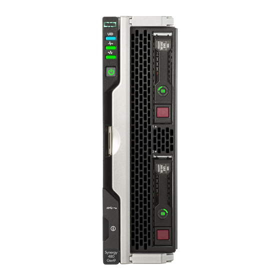
Page 7: Front Panel Components
iLO reboot is in progress.*Facility power is not present, power cord is not attached, no power supplies are installed, power supply failure has occurred, or the power button cable is disconnected. Front panel components Item Description Drive bay 1* Drive bay 2* External USB 3.0 connector (behind the serial label pull tab) Serial label pull tab Compute module handle release latch... -
Page 8: Hot-Plug Drive Led Definitions
Item Hard drive/SSD bay uFF drive bay NVMe drive bay numbering numbering numbering 1 and 101 2 and 102 Hot-plug drive LED definitions Item LED Status Definition Locate Solid blue The drive is being identified by a host application. Flashing blue The drive carrier firmware is being updated or requires an update. -
Page 9: Sff Flash Adapter Components And Led Definitions
Item LED Status Definition Flashing green The drive is rebuilding or performing a RAID migration, strip size migration, capacity expansion, or logical drive extension, or is erasing. Flashing amber/ The drive is a member of one or more logical drives and predicts the green drive will fail. -
Page 10: Nvme Ssd Components
Item Component Description Drive status LED • Off—The drive is not configured by a RAID controller • Solid green—The drive is a member of one or more logical drives. • Flashing green (4 Hz)—The drive is operating normally and has activity. -
Page 11: System Board Components
System board components Item Description TPM connector System battery Internal USB 3.0 connector Drive backplane connector Processor 1 DIMM slots (12) Processor 2 DIMM slots (12) HPE Smart Storage Battery connector Mezzanine connectors (M1, M2, and M3) Management/power connector System maintenance switch microSD card slot External USB 3.0 connector System maintenance switch... -
Page 12: Mezzanine Connector Definitions
Position Default Function Reserved Off = Power-on password is enabled. On = Power-on password is disabled. S6* ** Off = No function On = Restore default manufacturing settings Off = Set default boot mode to UEFI. On = Set default boot mode to legacy. —... -
Page 13: Dimm Slot Locations
Type C only ICM 3 and 6 * When an NVIDIA Tesla M6 GPU FIO Adapter for HPE Synergy 480 Gen9 Compute Module is installed in mezzanine connector 1, mezzanine connector 2 is not available for additional mezzanine cards. ** When installing a mezzanine option on mezzanine connector 2, processor 2 must be installed. -
Page 14: Components
Components Item Description MicroSD card slot SD1 card SD2 card LEDs Item Description Status Power LED Green: Device is on and at least one microSD card is functioning Red: Both microSD cards have failed SD2 LED On: microSD card has failed Off: microSD card is healthy SD1 LED On: microSD card has failed... -
Page 15: Component And Led Identification For Hpe Synergy Hardware
Component and LED identification for HPE Synergy hardware For more information about component and LED identification for HPE Synergy components, see the product- specific maintenance and service guide or the HPE Synergy 12000 Frame Setup and Installation Guide in the Hewlett Packard Enterprise Information Library . -
Page 16: Operations
Operations Powering up the compute module To power up the compute module, press the Power On/Standby button. Powering down the compute module Before powering down the compute module for any upgrade or maintenance procedures, perform a backup of critical data and programs. IMPORTANT: When the compute module is in standby mode, auxiliary power is still being provided to the system. -
Page 17: Removing The Compute Module
CAUTION: To prevent improper cooling and thermal damage, do not operate the compute module unless all bays are populated with either a component or a blank. Removing the compute module Procedure 1. Identify the proper compute module. 2. Power down the compute module. 3. -
Page 18: Removing The Compute Module End Cap
CAUTION: To prevent damage to electrical components, properly ground the compute module before beginning any installation procedure. Improper grounding can cause ESD. Removing the compute module end cap Procedure 1. Place the compute module on a flat, level work surface. 2. -
Page 19: Removing The Dimm Baffle
Removing the DIMM baffle Procedure 1. Power down the compute module. 2. Remove the compute module. 3. Place the compute module on a flat, level work surface. 4. Remove the access panel. IMPORTANT: When removing the right DIMM baffle, leave the Smart Storage Battery installed on the baffle. Use the blue pull tab to disconnect the Smart Storage Battery cable from the system board. -
Page 20: Removing The Front Panel/Drive Cage Assembly
Removing the front panel/drive cage assembly Procedure 1. Power down the compute module. 2. Remove the compute module. 3. Place the compute module on a flat, level work surface. 4. Remove the access panel. 5. Remove all drives. 6. Remove the front panel/drive cage assembly. Installing the compute module end cap Procedure 1. -
Page 21: Installing The Access Panel
Installing the access panel Procedure 1. Place the access panel on top of the graphics blade. 2. Slide the access panel forward until it clicks into place. Installing the DIMM baffles Procedure 1. Install the DIMM baffles. 2. Install the access panel. 3. - Page 22 Procedure 1. Install the front panel/drive cage assembly. 2. Install all drives. 3. Install the access panel. 4. Install the compute module. Operations...
-
Page 23: Setup
Setup Installation overview This section provides instructions for installing an HPE Synergy 480 Gen9 Compute Module in a frame for the first time. Installation of a compute module requires the following steps: Procedure 1. Installing supported options in the compute module. - Page 24 3. Prepare the compute module for installation by opening the compute module handle. 4. Install the compute module. Press the compute module handle near the release button to completely close the handle. Setup...
-
Page 25: Completing The Configuration
5. Review the compute module front panel LEDs to determine the compute module status. For more information on the compute module LEDs, see "Component identification." Completing the configuration HPE OneView, hosted on the HPE Synergy Composer appliance installed within an HPE Synergy 12000 Frame, enables you to comprehensively manage a Synergy system throughout the hardware life cycle. -
Page 26: Hardware Options Installation
Installing the drive option The compute module supports up to two SFF SAS, NVMe, solid state, or SATA (supported only with the HPE Synergy 480 Gen9 compute module backplane) drives. CAUTION: To prevent improper cooling and thermal damage, do not operate the compute module or the enclosure unless all drive and device bays are populated with either a component or a blank. - Page 27 3. Install the drive: • SAS, SATA, or solid state • NVMe 4. Determine the status of the drive from the drive LED definitions. Hardware options installation...
-
Page 28: Installing The Sff Flash Adapter Option
HPE Smart Array P240nr Controller • HPE H240nr Host Bus Adapter • HPE Smart Array P542D Controller (with HPE Synergy 480 Gen9 compute module backplane installed) To install the component: Procedure 1. Remove the drive blank. 2. Install the uFF drives in the SFF flash adapter. -
Page 29: Installing The Hpe Smart Storage Battery Option
CAUTION: In systems that use external data storage, be sure that the compute module is the first unit to be powered down and the last to be powered back up. Taking this precaution ensures that the system does not erroneously mark the drives as failed when the compute module is powered up. To install the component: Procedure 1. -
Page 30: Installing The Mezzanine Card Options
Install the DIMM baffle. Connect the Smart Storage Battery to the system board. To locate the Smart Storage Battery connector, see the "System board components." Install the access panel. 10. Install the compute module. 11. Power up the compute module. Installing the mezzanine card options IMPORTANT: For more information about the association between the mezzanine bay and the interconnect bays, see... -
Page 31: Installing The Hpe Smart Array P542D Controller Mezzanine Option
Procedure Power down the compute module. Remove the compute module. Place the compute module on a flat, level work surface. Remove the access panel. Locate the appropriate mezzanine connector. To locate the connector, see the "System board components." Remove the mezzanine connector cover, if installed. Install the mezzanine card. -
Page 32: Memory Options
Remove the front panel/drive cage assembly. Install the mezzanine card. Press firmly on the PRESS HERE label above the mezzanine connector to seat the card. Install and route the HPE Smart Array P542D SAS cable from the premium backplane to the HPE Smart Array P542D Controller mezzanine card. -
Page 33: Smartmemory
• RDIMMs offer address parity protection. • LRDIMMs support higher densities than single- and dual-rank RDIMMs, and higher speeds than quad-rank RDIMMs. This support enables you to install more high-capacity DIMMs, resulting in higher system capacities and higher bandwidth. All types are referred to as DIMMs when the information applies to all types. When specified as LRDIMM or RDIMM, the information applies to that type only. -
Page 34: Dimm Ranks
Memory subsystem Population order Slot number (Processor Slot number (Processor channel A E I 12 11 10 1 2 3 B F J 9 8 7 4 5 6 C G K 1 2 3 12 11 10 D H L 4 5 6 9 8 7 For the location of the slot numbers, see "DIMM slot locations."... -
Page 35: Memory Configurations
Item Description Definition Capacity 8 GB 16 GB 32 GB 64 GB 128 GB Rank 1R = Single-rank 2R = Dual-rank 4R = Quad-rank 8R = Octal-rank Data width on DRAM x4 = 4-bit x8 = 8-bit Memory generation DDR4 Maximum memory speed 2400 MT/s CAS latency... -
Page 36: Advanced Ecc Memory Configuration
DIMM type DIMM rank Capacity (GB) One processor Two processors (GB) (GB) RDIMM Dual RDIMM Dual LRDIMM Dual LRDIMM Quad 1536 LRDIMM Octal 1536 3072 For the latest memory configuration information, see the QuickSpecs on the Hewlett Packard Enterprise website (http://www.hpe.com/info/qs). Advanced ECC memory configuration Advanced ECC memory is the default memory protection mode for this compute module. -
Page 37: Advanced Ecc Population Guidelines
For more information about compute module memory, see http://www.hpe.com/info/memory. DIMM speeds are supported as indicated in the following table. Populated slots (per Rank DIMM Speeds supported channel) (MT/s) Single, dual, or quad RDIMM or LRDIMM 2400 Single RDIMM 2133 Dual or quad RDIMM or LRDIMM 2400 Single... -
Page 38: Installing The Processor Option
Remove the access panel. Remove the DIMM baffle. Install the DIMM. Install all DIMM baffles. Install the access panelInstall the access panel. Install the compute module. 10. Power up the compute module. To configure the memory mode, use UEFI System Utilities. Installing the processor option WARNING: To reduce the risk of personal injury from hot surfaces, allow the drives and the internal system... - Page 39 Procedure Update the system ROM. Locate and download the latest ROM version from the Hewlett Packard Enterprise website at http:// www.hpe.com/support. Follow the instructions on the website to update the system ROM. Power down the compute module. Remove the compute module. Remove the access panel.
- Page 40 CAUTION: THE PINS ON THE SYSTEM BOARD ARE VERY FRAGILE AND EASILY DAMAGED. To avoid damage to the system board, do not touch the processor or the processor socket contacts. Install the processor. Verify that the processor is fully seated in the processor retaining bracket by visually inspecting the processor installation guides on either side of the processor.
- Page 41 CAUTION: Do not press down on the processor. Pressing down on the processor might damage the processor socket and the system board. Press only in the area indicated on the processor retaining bracket. CAUTION: Close and hold down the processor cover socket while closing the processor locking levers. The levers should close without resistance.
-
Page 42: Hp Trusted Platform Module Option
14. Install all DIMM baffles. 15. Install the access panel. 16. Install the compute module. HP Trusted Platform Module option When installing or replacing TPM, observe the following guidelines: • Do not remove an installed TPM. Once installed, the TPM becomes a permanent part of the system board. -
Page 43: Installing The Trusted Platform Module Board
CAUTION: Always observe the guidelines in this document. Failure to follow these guidelines can cause hardware damage or halt data access. Installing the Trusted Platform Module board WARNING: To reduce the risk of personal injury from hot surfaces, allow the drives and the internal system components to cool before touching them. -
Page 44: Retaining The Recovery Key/Password
12. Install the front panel/drive cage assembly. 13. Install all drives. 14. Install the DIMM baffles. 15. Install the access panel. 16. Install the compute module. 17. Power up the compute module. Retaining the recovery key/password The recovery key/password is generated during BitLocker setup, and can be saved and printed after BitLocker is enabled. - Page 45 • If TPM 1.2 is installed, then select No Action, Enable, Disable, or Clear. • If TPM 2.0 is installed, then select No Action or Clear. 5. Select Visible to set the TPM Visibility, if necessary. 6. Press the F10 key to save your selection. 7.
-
Page 46: Cabling
Cabling Cabling resources Cabling configurations and requirements vary depending on the product and installed options. For more information about product features, specifications, options, configurations, and compatibility, see the product QuickSpecs on the Hewlett Packard Enterprise website . HPE Smart Storage Battery cabling HPE Smart Array P542D Controller cabling Cabling... -
Page 47: Software And Configuration Utilities
Software and configuration utilities Management and diagnostic tools <Will there be any SW overviews here?> For more information, see the HPE Synergy Configuration and Compatibility Guide on the Hewlett Packard Enterprise website. Software and configuration utilities... -
Page 48: Removing And Replacing The System Battery
Removing and replacing the system battery If the compute module no longer automatically displays the correct date and time, then replace the battery that provides power to the real-time clock. Under normal use, battery life is 5 to 10 years. WARNING: The computer contains an internal lithium manganese dioxide, a vanadium pentoxide, or an alkaline battery pack. -
Page 49: Warranty And Regulatory Information
Warranty and regulatory information Warranty information HPE ProLiant and x86 Servers and Options HPE Enterprise Servers HPE Storage Products HPE Networking Products Regulatory information Safety and regulatory compliance For important safety, environmental, and regulatory information, see Safety and Compliance Information for Server, Storage, Power, Networking, and Rack Products, available at the Hewlett Packard Enterprise website. -
Page 50: Turkey Rohs Material Content Declaration
• Belarus: • Kazakhstan: Manufacturing date: The manufacturing date is defined by the serial number. CCSYWWZZZZ (serial number format for this product) Valid date formats include: • YWW, where Y indicates the year counting from within each new decade, with 2000 as the starting point; for example, 238: 2 for 2002 and 38 for the week of September 9. -
Page 51: Electrostatic Discharge
Electrostatic discharge Preventing electrostatic discharge To prevent damaging the system, be aware of the precautions you must follow when setting up the system or handling parts. A discharge of static electricity from a finger or other conductor may damage system boards or other static-sensitive devices. -
Page 52: Specifications
Specifications Environmental specifications Specification Value Temperature range* — Operating 10°C to 35°C (50°F to 95°F) Non-operating -30°C to 60°C (-22°F to 140°F) Relative humidity (noncondensing)** — Operating 10% to 90% @ 28°C (82.4°F) Non-operating 5% to 95% @ 38.7°C (101.7°F) Altitude†... -
Page 53: Documentation And Troubleshooting Resources For Hpe Synergy
Documentation and troubleshooting resources for HPE Synergy HPE Synergy documentation The Hewlett Packard Enterprise Information Library (www.hpe.com/info/synergy-docs) is a task-based repository. It includes installation instructions, user guides, maintenance and service guides, best practices, and links to additional resources. Use this website to obtain the latest documentation, including: •... -
Page 54: Best Practices For Hpe Synergy Firmware And Driver Updates
and configuration utilities to support HPE Synergy. The guide is task-based and covers the documentation and resources for all supported software and configuration utilities available for: • HPE Synergy setup and configuration • OS deployment • Firmware updates • Troubleshooting •... -
Page 55: Hpe Error Message Guide For Hpe Synergy
HPE Error Message Guide for HPE Synergy The HPE Error Message Guide for HPE Synergy is in the Hewlett Packard Enterprise Information Library (www.hpe.com/info/synergy-docs). It provides information for resolving common problems associated with specific error messages received for both HPE Synergy hardware and software components. HPE OneView and HPE OneView REST API scripting help The HPE OneView Help, the HPE OneView REST API Scripting Help, and the HPE OneView API Reference are readily accessible, embedded online help available within the HPE OneView user interface. -
Page 56: Support And Other Resources
Hewlett Packard Enterprise Support Center More Information on Access to Support Materials page. IMPORTANT: : Access to some updates might require product entitlement when accessed through the Hewlett Packard Enterprise Support Center. You must have an HP Passport set up with relevant entitlements. Websites •... -
Page 57: Customer Self Repair
Customer Self Repair Hewlett Packard Enterprise products are designed with many Customer Self Repair (CSR) parts to minimize repair time and allow for greater flexibility in performing defective parts replacement. If during the diagnosis period Hewlett Packard Enterprise (or Hewlett Packard Enterprise service providers or service partners) identifies that the repair can be accomplished by the use of a CSR part, Hewlett Packard Enterprise will ship that part directly to you for replacement. - Page 58 retourner la pièce défectueuse. Si c'est le cas, vous devez le faire dans le délai indiqué, généralement cinq (5) jours ouvrés. La pièce et sa documentation doivent être retournées dans l'emballage fourni. Si vous ne retournez pas la pièce défectueuse, Hewlett Packard Enterprise se réserve le droit de vous facturer les coûts de remplacement.
- Page 59 HINWEIS: Einige Hewlett Packard Enterprise Teile sind nicht für Customer Self Repair ausgelegt. Um den Garantieanspruch des Kunden zu erfüllen, muss das Teil von einem Hewlett Packard Enterprise Servicepartner ersetzt werden. Im illustrierten Teilekatalog sind diese Teile mit „No“ bzw. „Nein“...
- Page 60 Para obtener más información acerca del programa de Reparaciones del propio cliente de Hewlett Packard Enterprise, póngase en contacto con su proveedor de servicios local. Si está interesado en el programa para Norteamérica, visite la página web de Hewlett Packard Enterprise CSR. Customer Self Repair Veel onderdelen in Hewlett Packard Enterprise producten zijn door de klant zelf te repareren, waardoor de reparatieduur tot een minimum beperkt kan blijven en de flexibiliteit in het vervangen van defecte onderdelen...
- Page 61 OBSERVAÇÃO: Algumas peças da Hewlett Packard Enterprise não são projetadas para o reparo feito pelo cliente. A fim de cumprir a garantia do cliente, a Hewlett Packard Enterprise exige que um técnico autorizado substitua a peça. Essas peças estão identificadas com a marca "No" (Não), no catálogo de peças ilustrado. Conforme a disponibilidade e o local geográfico, as peças CSR serão enviadas no primeiro dia útil após o pedido.
- Page 62 Support and other resources...
-
Page 63: Remote Support
Remote support Remote support is available with supported devices as part of your warranty or contractual support agreement. It provides intelligent event diagnosis, and automatic, secure submission of hardware event notifications to Hewlett Packard Enterprise, which will initiate a fast and accurate resolution based on your product's service level. -
Page 64: Acronyms And Abbreviations
Acronyms and abbreviations Advanced Memory Protection application program interface Automatic Server Recovery certificate signing request HP SUM HP Smart Update Manager HPE SSA HPE Smart Storage Administrator Integrated Lights-Out Integrated Management Log JSON JavaScript Object Notation keyboard, video, and mouse... - Page 65 Trusted Platform Module UEFI Unified Extensible Firmware Interface universal serial bus Version Control Agent VCRM Version Control Repository Manager Acronyms and abbreviations...
-
Page 66: Documentation Feedback
Documentation feedback Hewlett Packard Enterprise is committed to providing documentation that meets your needs. To help us improve the documentation, send any errors, suggestions, or comments to Documentation Feedback (docsfeedback@hpe.com). When submitting your feedback, include the document title, part number, edition, and publication date located on the front cover of the document.
Need help?
Do you have a question about the Synergy 480 Gen9 and is the answer not in the manual?
Questions and answers