
Related Manuals for HP E3456A


Summary of Contents for HP E3456A
- Page 1 (217) 352-9330 | Click HERE Find the Keysight / Agilent E3456A at our website:...
- Page 2 Agilent Test & Measurement website, www.tm.agilent.com. HP References in this Manual This manual may contain references to HP or Hewlett-Packard. Please note that Hewlett-Packard's former test and measurement, semiconductor products and chemical analysis businesses are now part of Agilent Technologies. We have made no changes to this manual copy.
- Page 3 User’s Guide Publication number E3456-97002 July 1998 For Safety information, Warranties, and Regulatory information, see the pages behind the index. © Copyright Hewlett-Packard Company 1994-1998 All Rights Reserved Emulation for the PowerPC MPC500...
-
Page 4: Emulation For The Powerpc Mpc500-At A Glance
Motorola’s embedded PowerPC MPC500 microprocessors provide a development port (also known as a debug port) that lets tools like the HP E3456A emulation probe or the HP 16610A emulation module give you capabilities like: • Stopping or starting program execution. -
Page 5: Emulation Probe
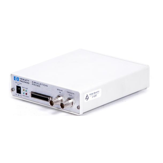
Emulation Probe The HP E3456A emulation probe is a stand-alone unit that has its own power supply and local area network (LAN) interface. The HP E3456A emulation probe is typically used in situations where only its capabilities are needed, for example, by software developers using debuggers to debug program code. -
Page 6: In This Book
This book also describes the specifications and characteristics of the emulation probe/module, and it contains service information. See Also If you’re using the Emulation Control Interface in the HP 16600A/ 16700A-series logic analysis system to control the emulation probe/ module, see the logic analysis system’s on-line help. -
Page 7: Table Of Contents
Contents Emulation for the PowerPC MPC500—At a Glance Emulation Probe 3 Emulation Module 3 In This Book 1 Installing the Emulation Probe Overview of Installation and Setup 14 Equipment and Requirements 16 Supplied Equipment and Software 16 Additional Equipment and Software Required 17 Other Optional Equipment 18 Powering-On and Powering-Off the Emulation Probe 19 To power on the system 19... - Page 8 Supplied Equipment and Software 46 Additional Equipment and Software Required 47 Installing into a Logic Analysis System 48 To install in a HP 16700A-series logic analysis system 48 To install in a HP 16600A-series logic analysis system 51 To test the emulation module 53...
- Page 9 Contents Preparing for a Debugger 59 To connect the logic analysis system to the LAN 59 To change the port number of an emulation module 60 To verify LAN communication with the emulation module 61 3 Connecting to a Target System Designing the Target System for an Emulation Probe/Module 64 Target System Requirements 64 Debug Port Connection 64...
- Page 10 Contents Setting the MPC5xx Configuration Options 81 To configure the processor type 81 To configure the processor clock speed 82 To configure the debug port connection type 83 To configure the reset configuration word source 84 To configure the “Break In” type 84 To configure the Trigger Out BNC 85 To configure the Trigger In BNC 85 To configure the BNC break type 86...
- Page 11 Contents Using the Microtec Research Debugger 103 To get started 103 To configure the emulation probe/module using an INCLUDE file 106 To perform common debugger tasks 106 To send commands to the emulation probe/module 107 To view commands sent by XRAY 107 To disconnect from the emulation probe/module and target 108 Error conditions 108 Using the Software Development Systems Debugger 110...
- Page 12 Contents Solving Target System Problems 128 What to check first 128 To interpret the initial prompt 129 If interrupts are non-recoverable 130 If hardware breakpoints have no effect 131 If the target resets itself 132 If running from reset causes problems 132 If you see the “!ASYNC_STAT 173!”...
- Page 13 Contents Glossary Index...
- Page 14 Contents...
-
Page 15: Installing The Emulation Probe
Installing the Emulation Probe... -
Page 16: Overview Of Installation And Setup
Chapter 1: Installing the Emulation Probe Overview of Installation and Setup Overview of Installation and Setup Follow these steps to connect your equipment. 1 Check that you received all of the necessary equipment. See “Equipment and Requirements” on page 16. 2 Disconnect power from the target system, emulation probe, and logic analyzer before you make or break connections. - Page 17 Chapter 1: Installing the Emulation Probe Overview of Installation and Setup Emulation probe HP E5900A Connect power supply Connect to LAN Update emulation probe firmware (if necessary) Connect emulation probe Connect emulation probe to target interface module Connect target interface module to target Installation done.
-
Page 18: Equipment And Requirements
• A 10-pin ribbon cable for connecting the target interface module (TIM) to a debug port connector in the target system. • Emulation Control Interface software. • An emulation probe loopback test board (HP part number E3496-66502). • This User’s Guide. -
Page 19: Additional Equipment And Software Required
You can use a third-party high-level source debugger to access and control the emulation module. Debuggers can run on PC or UNIX workstations that are also on the local area network (LAN). Or, you can use the HP 16600A/16700A-series logic analysis system’ s Emulation Control Interface. -
Page 20: Other Optional Equipment
Other Optional Equipment You can also use the emulation probe with: • The HP 16600A/16700A-series logic analysis system. • The HP E2490A analysis probe for Motorola Embedded PowerPC MPC505/ 509 microprocessors. The analysis probe captures microprocessor signals for logic analysis. The... -
Page 21: Powering-On And Powering-Off The Emulation Probe
Chapter 1: Installing the Emulation Probe Powering-On and Powering-Off the Emulation Probe Powering-On and Powering-Off the Emulation Probe It’s important to follow the proper power-on or power-off sequences so that your target system, the emulation probe, and other equipment are not damaged. - Page 22 Hewlett- Packard sales and service office. WARNING: Use only the supplied HP power supply and cord. Failure to use the proper power supply could result in electric shock. CAUTION: Use only the supplied HP power supply and cord. Failure to use the proper...
-
Page 23: Connecting The Emulation Probe To A Lan
Connecting the Emulation Probe to a LAN The emulation probe communicates with a debugger (running on a PC or UNIX workstation), or with the HP 16600A/16700A-series logic analysis system, via a local area network (LAN). So, the first thing to do when installing an emulation probe is to set its LAN parameters. -
Page 24: To Get The Ip And Gateway Addresses
Chapter 1: Installing the Emulation Probe Connecting the Emulation Probe to a LAN The IP address and other network parameters are stored in nonvolatile memory within the emulation probe. To get the IP and gateway addresses 1 Obtain the following information from your local network administrator or system administrator: •... -
Page 25: To Configure Lan Parameters Using The Built-In Terminal Interface
Chapter 1: Installing the Emulation Probe Connecting the Emulation Probe to a LAN The link-level address (LLA) is printed on a label above the LAN connectors on the emulation probe. This address is configured in each emulation probe shipped from the factory and cannot be changed. IP Address of Emulation Probe __________________________ Hostname of Emulation Probe __________________________ Gateway Address __________________________... - Page 26 Chapter 1: Installing the Emulation Probe Connecting the Emulation Probe to a LAN in terminal interface. 4 Display the current LAN configuration values by entering the lan command: R>lan lan is disabled lan -i 0.0.0.0 lan -g 0.0.0.0 lan -p 6470 Ethernet Address : 08000903212f The “lan -i”...
- Page 27 Chapter 1: Installing the Emulation Probe Connecting the Emulation Probe to a LAN 6 Disconnect the power cord from the emulation probe, and connect the emulation probe to your network. This connection can be made by using either the 10BASE-T connector or the 10BASE2 (BNC) connector on the emulation probe.
-
Page 28: To Configure Lan Parameters Using Bootp
Chapter 1: Installing the Emulation Probe Connecting the Emulation Probe to a LAN To assign an IP address of 192.6.94.2 to the emulation probe, enter the Example following command: R>lan -i 192.6.94.2 Now, cycle power on the emulation probe so that the new address will take effect. - Page 29 Chapter 1: Installing the Emulation Probe Connecting the Emulation Probe to a LAN # Specific emulator entry specifying hardware address # (link-level address) and ip address. hpprobe.div.hp.com:\ :tc=hp64700.global:\ :ha=080009090B0E:\ :ip=192.6.29.31 In this example, the “ha=080009090B0E” identifies the link-level address of the emulation probe. The “ip=192.6.29.31” specifies the IP address that is assigned to the emulation probe.
-
Page 30: To Set The 10Base-T Configuration Switches
Chapter 1: Installing the Emulation Probe Connecting the Emulation Probe to a LAN configuration switches” on page 28. Set all other switches to ON. 5 Connect the power cord to the emulation probe. 6 Verify that the power light stays on after 10 seconds. The IP address will be stored in EEPROM. -
Page 31: To Verify Lan Communications
Chapter 1: Installing the Emulation Probe Connecting the Emulation Probe to a LAN When switch S7 is set to ON, the LAN port operates at standard 10BASE-T levels. A maximum of 100 meters of UTP cable can be used. • If your network doesn’t support Link Beat integrity checking or if the emulation probe is connected to a non 10BASE-T network (such as StarLAN) set this switch to LINK BEAT OFF (0 or OPEN). - Page 32 Chapter 1: Installing the Emulation Probe Connecting the Emulation Probe to a LAN Example $ telnet 192.35.12.6 R>lan lan is enabled lan -i 192.35.12.6 lan -g 0.0.0.0 lan -p 6470 Ethernet Address : 08000F090B30 See Also If you encounter problems, see “Solving LAN Communication Problems”...
-
Page 33: Solving Lan Communication Problems
Chapter 1: Installing the Emulation Probe Solving LAN Communication Problems Solving LAN Communication Problems If you cannot verify LAN communication If you cannot verify LAN communication using the procedure in “To verify LAN communications” on page 29, or if the commands are not accepted by the emulation probe: Make sure that you have connected the emulation probe to the proper power source and that the power light is lit. -
Page 34: If You Have Lan Connection Problems
If you have LAN connection problems If the emulation probe does not accept commands from the HP 16600A/16700A-series logic analysis system or a debugger: 1. Check that switch S1 is “0” (attached to LAN, not RS-232). 2. Check that switch S5 is in the correct position for your LAN interface (either 10BASE2 or 10BASE-T). -
Page 35: If The "Pol" Led Is Lit
Chapter 1: Installing the Emulation Probe Solving LAN Communication Problems gateway if you are connecting from another subnet, or 0.0.0.0 if you are connecting from the local subnet. “lan -p” shows the port is 6470. If the “POL” LED is lit The “POL”... -
Page 36: Connecting A Terminal To The Emulation Probe's Serial Port
Chapter 1: Installing the Emulation Probe Connecting a Terminal to the Emulation Probe’s Serial Port Connecting a Terminal to the Emulation Probe’s Serial Port To set up a serial connection, you will need to: • Set the serial configuration switches. •... -
Page 37: To Connect A Serial Cable
Connect an RS-232C modem cable from the host computer to the emulation probe. The recommended cable is HP part number C2932A. This is a 9-pin cable with one-to-one pin connections. If you want to build your own RS-232 cable, follow the pinout shown in... -
Page 38: To Verify Serial Communications
Chapter 1: Installing the Emulation Probe Connecting a Terminal to the Emulation Probe’s Serial Port To verify serial communications 1 Start a terminal emulator program on the host computer. If you are using a PC, the Terminal application in MS Windows 3.1, or the HyperTerminal application in MS Windows 95/NT, will work fine. - Page 39 Chapter 1: Installing the Emulation Probe Connecting a Terminal to the Emulation Probe’s Serial Port Copyright (c) Hewlett-Packard Co. 1987 All Rights Reserved. Reproduction, adaptation, or translation without prior written permission is prohibited, except as allowed under copyright laws. HPE3499A Series Emulation System Version: A.07.53 01Mar98 Location:...
-
Page 40: Solving Serial Communication Problems
DCE device. If you are using the wrong type of cable, no prompt will be displayed. A cable with one-to-one connections will work with a PC or an HP 9000 Series 700 workstation. If you have RS-232 connection problems with the MS Windows Terminal program Remember that Windows 3.1 only allows two active RS-232... - Page 41 Chapter 1: Installing the Emulation Probe Solving Serial Communication Problems settings as follows: When you are connected, hit the Enter key. You should get a prompt back. If nothing echos back, check the switch settings on the emulation probe. If the switches are in the correct position and you still do not get a prompt when you hit return, try turning OFF the power to the emulation probe and turning it ON again.
-
Page 42: Updating Emulation Probe Firmware
You must update the firmware if: • You need to change the personality of the emulation probe for a new processor. • You have an updated version of the firmware from HP. To display current firmware version information • Use telnet or a terminal emulator to access the built-in “terminal interface”... - Page 43 Chapter 1: Installing the Emulation Probe Updating Emulation Probe Firmware firmware. If HP sends you firmware on a floppy disk, install the firmware from the floppy disk. The README file on the floppy disk contains instructions for installing the firmware using a PC or workstation.
- Page 44 Chapter 1: Installing the Emulation Probe Updating Emulation Probe Firmware...
-
Page 45: Installing The Emulation Module
Installing the Emulation Module... -
Page 46: Overview Of Installation And Setup
Chapter 2: Installing the Emulation Module Overview of Installation and Setup Overview of Installation and Setup Follow these steps to connect your equipment. 1 Check that you received all of the necessary equipment. See “Equipment and Requirements” on page 46. 2 Disconnect power from the target system and logic analyzer before you make or break connections. - Page 47 Chapter 2: Installing the Emulation Module Overview of Installation and Setup Emulation module HP E5901A Install emulation module (if necessary) Install software on logic analysis system Update emulation module firmware (if necessary) Connect emulation module Connect emulation module to target...
-
Page 48: Equipment And Requirements
• A 10-pin ribbon cable for connecting the target interface module (TIM) to a debug port connector in the target system. • One Torx T-10 and one Torx T-15 screwdriver. • An emulation module loopback test board (HP part number E3496-66502) • This User’s Guide. -
Page 49: Additional Equipment And Software Required
Chapter 2: Installing the Emulation Module Equipment and Requirements Additional Equipment and Software Required The emulation module requires: • An HP 16600A/16700A-series logic analysis system into which it can be installed. • Interface software that gives you access to the emulation module’s functionality. -
Page 50: Installing Into A Logic Analysis System
To install in a HP 16700A-series logic analysis system Or, to install in an HP 16701A expansion frame: You will need a T-10 Torx screw driver. 1 Turn off the logic analysis system and REMOVE THE POWER CORD. - Page 51 Chapter 2: Installing the Emulation Module Installing into a Logic Analysis System 4 Remove the slot cover. You may use either slot. 5 Install the emulation module.
- Page 52 Chapter 2: Installing the Emulation Module Installing into a Logic Analysis System 6 Connect the cable and re-install the screws. You may connect the cable to either of the two connectors. If you have two emulation modules, note that many debuggers will work only with the “first”...
-
Page 53: To Install In A Hp 16600A-Series Logic Analysis System
See “Updating Emulation Module Firmware” on page 56 for information on giving the emulation module a “personality” for your target processor. To install in a HP 16600A-series logic analysis system You will need a T-10 Torx screw driver. 1 Turn off the logic analysis system and REMOVE THE POWER CORD. - Page 54 Chapter 2: Installing the Emulation Module Installing into a Logic Analysis System 3 Remove the slot cover. 4 Install the emulation module. 5 Connect the cable and re-install the screws.
-
Page 55: To Test The Emulation Module
Chapter 2: Installing the Emulation Module Installing into a Logic Analysis System 6 Reinstall the cover. Tighten the screws snugly (2 N m or 18 inch-pounds). 7 Plug in the power cord, reconnect the other cables, and turn on the logic analysis system. The new emulation module will be shown in the system window. -
Page 56: Installing Software
To install software from CD-ROM Installing a processor support package from a CD-ROM will take just a few minutes. If the processor support package requires an update to the HP 16600A/16700A-series logic analysis system’s operating system, installation may take approximately 45 minutes. - Page 57 Chapter 2: Installing the Emulation Module Installing Software NOTE: If the CD-ROM drive is not connected, see the instructions printed on the CD-ROM package. 1 Turn on the CD-ROM drive first; then, turn on the logic analysis system. 2 Insert the CD-ROM in the drive. 3 Click the System Admin icon.
-
Page 58: Updating Emulation Module Firmware
• You need to change the personality of the emulation module for a new microprocessor. • You have an updated version of the firmware from HP. Always update firmware by installing a processor support package. This will ensure that the version of the Emulation Control Interface software is compatible the version of the emulator firmware. -
Page 59: To Update Firmware Using The Setup Assistant
The Setup Assistant is an on-line tool for connecting and configuring your logic analysis system for microprocessor and bus analysis. The Setup Assistant is available on the HP 16600A/16700A-series logic analysis systems. This menu-driven tool will guide you through the connection procedures for connecting the logic analyzer to an analysis probe, an emulation module, or other supported equipment. - Page 60 Chapter 2: Installing the Emulation Module Updating Emulation Module Firmware 2 Start the Setup Assistant by clicking its icon in the system window. 3 Follow the instructions displayed by the Setup Assistant. “Installing Software” on page 54 for instructions on how to install a the See Also processor support package from the CD-ROM.
-
Page 61: Preparing For A Debugger
Chapter 2: Installing the Emulation Module Preparing for a Debugger Preparing for a Debugger When using a debugger with an emulation module in the HP 16600A/ 16700A-series logic analysis system, the logic analysis system must be set up on the local area network (LAN). -
Page 62: To Change The Port Number Of An Emulation Module
Chapter 2: Installing the Emulation Module Preparing for a Debugger To change the port number of an emulation module To view or change the port number of an emulation module: 1 Click on the emulation module icon in the system window of the logic analysis system;... -
Page 63: To Verify Lan Communication With The Emulation Module
Chapter 2: Installing the Emulation Module Preparing for a Debugger To verify LAN communication with the emulation module 1 Telnet to the IP address. For example, on a UNIX system, enter “telnet <IP_address> 6472". This connection will give you access to the emulation module’s built-in terminal interface. - Page 64 Chapter 2: Installing the Emulation Module Preparing for a Debugger...
-
Page 65: Connecting To A Target System
Connecting to a Target System... -
Page 66: Designing The Target System For An Emulation Probe/Module
There is also 1.79 Kohm pullup to 3.3 volts on the RESET and SRESET lines. The HP emulation probe/module adds about 40 pF to all target system signals routed to the debug connector. This added capacitance may reduce the rise time of the RESET and SRESET signals beyond the processor specifications. - Page 67 Chapter 3: Connecting to a Target System Designing the Target System for an Emulation Probe/Module probe/module requires a debug port (BDM) connector in the target system. The connector should be a dual row header strip (“Berg connector”), 10 pins per inch, with 25 mil pins. There are three possible pin outs of the BDM connector for the MPC555.
- Page 68 Chapter 3: Connecting to a Target System Designing the Target System for an Emulation Probe/Module Use the following commands to configure the emulation probe/module for this configuration: cf proc=MPC555 cf dbgconfig=1 rst -m NOTE: The MIOS1TPCR (0x0030 6800) register is modified to configure J18 and K18 as VFLS0/1 pins.
-
Page 69: Sypcr Register
Chapter 3: Connecting to a Target System Designing the Target System for an Emulation Probe/Module MPC555 Debug Port Connector, Option 3 For maximum I/O configuration: The E3497-66502 target interface module (TIM) requires 10k ohm pull-up resistors on pins 1 and 6. The E3497-66503 target interface module (TIM) has 10k ohm pull-up resistors on pins 1 and 6. -
Page 70: On-Chip Flash Support
Designing the Target System for an Emulation Probe/Module On-Chip Flash Support The emulation probe/module will not directly support on-chip flash. Flash support should be provided by 3rd party debug vendors. Fast Download The HP probe will automatically use the chip’s internally supported fast download mode. -
Page 71: Making The Target System Connection
NOTE: The HP E2490A analysis probe for MPC505/509 microprocessors does not support the MPC555 microprocessor. After you have connected the emulation probe/module to your target system, you may need to update the firmware in the emulation module. - Page 72 Chapter 3: Connecting to a Target System Making the Target System Connection 3 Plug the other end of the 50-pin cable into the target interface module. 4 Plug one end of the 10-pin cable into the target interface module. 5 Plug the other end of the 10-pin cable into the debug port connector on the target system.
-
Page 73: To Connect To The Analysis Probe
Chapter 3: Connecting to a Target System Making the Target System Connection 6 Turn on the power to the logic analysis system and then the target system. For information on designing a target system for use with the See Also emulation module, see “Designing the Target System for an Emulation Probe/Module”... - Page 74 Chapter 3: Connecting to a Target System Making the Target System Connection...
-
Page 75: To Verify Communication With The Target System
Chapter 3: Connecting to a Target System Making the Target System Connection To verify communication with the target system 1 Turn on the target system. 2 Start the Emulation Control Interface. If the electrical connections are correct, and if the emulator firmware and analysis probe or TIM match your target processor, the Run Control window should be displayed:... - Page 76 Chapter 3: Connecting to a Target System Making the Target System Connection...
-
Page 77: Configuring The Emulation Probe/Module
Configuring the Emulation Probe/ Module... - Page 78 Chapter 4: Configuring the Emulation Probe/Module The emulation probe/module has several user-configurable options. These options may be customized for specific target systems and saved in configuration files for future use.
-
Page 79: Entering Emulation Probe/Module Commands
• The emulation probe/module’s built-in terminal interface. • Your debugger, if it provides an “emulator configuration” window that can be used with this HP emulation module. To use the Emulation Control Interface The easiest way to configure the emulation module is to use the Emulation Control Interface. - Page 80 Chapter 4: Configuring the Emulation Probe/Module Entering Emulation Probe/Module Commands Set the configuration options, as needed. The configuration selections will take effect when you close the configuration window or when you move the mouse pointer outside the window. Save the configuration settings. To save the configuration settings, open the File Manager window and click Save..
-
Page 81: To Use The Built-In Command Interface
Chapter 4: Configuring the Emulation Probe/Module Entering Emulation Probe/Module Commands information on each of the configuration options. Help in the Emulation Control Interface menu for help on starting an Emulation Control session. To use the built-in command interface If you are unable to configure the emulation probe/module with the Emulation Control Interface or a debugger interface, you can configure the emulation probe/module using the built-in “terminal interface”... -
Page 82: To Use A Debugger Interface
- Trigger out control M> To use a debugger interface Because the HP emulation probe/module can be used with several third-party debuggers, specific details for sending the configuration commands from the debugger to the emulation module cannot be given here. However, all debuggers should provide a way of directly entering terminal mode commands to the emulation module. -
Page 83: Setting The Mpc5Xx Configuration Options
Chapter 4: Configuring the Emulation Probe/Module Setting the MPC5xx Configuration Options Setting the MPC5xx Configuration Options You must configure the processor probe to work with your target system. The following options can be configured using the Emulation Control Interface or using built-in commands: •... -
Page 84: To Configure The Processor Clock Speed
Chapter 4: Configuring the Emulation Probe/Module Setting the MPC5xx Configuration Options The cfsave -s command will store this configuration in the processor probe’s flash memory. The cfsave -r command will restore this configuration. To configure the processor clock speed The BDM communication speed will be 1/3 of the configured processor clock speed. -
Page 85: To Configure The Debug Port Connection Type
Chapter 4: Configuring the Emulation Probe/Module Setting the MPC5xx Configuration Options To configure the debug port connection type This configuration option is valid when the processor type has been configured for MPC555. -
Page 86: To Configure The Reset Configuration Word Source
Chapter 4: Configuring the Emulation Probe/Module Setting the MPC5xx Configuration Options To configure the reset configuration word source This configuration option is valid when the processor type has been configured for MPC505 or MPC509. To configure the “Break In” type This option affects how the emulation module will react to a trigger in an intermodule measurement. -
Page 87: To Configure The Trigger Out Bnc
Chapter 4: Configuring the Emulation Probe/Module Setting the MPC5xx Configuration Options To configure the Trigger Out BNC To configure the Trigger In BNC... -
Page 88: To Configure The Bnc Break Type
Chapter 4: Configuring the Emulation Probe/Module Setting the MPC5xx Configuration Options To configure the BNC break type To configure restriction to real-time runs... -
Page 89: Testing The Emulation Probe/Module And The Target System
Chapter 4: Configuring the Emulation Probe/Module Testing the Emulation Probe/Module and the Target System Testing the Emulation Probe/Module and the Target System After you have connected and configured the emulation probe/module, you should perform some simple tests to verify that everything is working. - Page 90 Chapter 4: Configuring the Emulation Probe/Module Testing the Emulation Probe/Module and the Target System 2 Use the Load Executable window to download the program into RAM or flash memory. 3 Use the Breakpoints window to set breakpoints. Use the Registers window to initialize register values. The new register or breakpoint values are sent to the processor when you press the Enter key or when you move the cursor out of the selected register field.
-
Page 91: Using Debuggers
Using Debuggers... - Page 92 To use a debugger with the emulation probe/module, you need: • A debugger that is compatible with the emulation probe/module. Ask your debugger vendor whether the debugger can be used with an HP emulation probe (which is also known as a “processor probe” or “software probe”) or an HP emulation module.
- Page 93 Chapter 5: Using Debuggers • To have the logic analysis system user interface displayed on your PC or workstation screen along with the debugger, your computer needs to be running X Windows server software. Most UNIX workstations run X Windows server software, but on a PC you may need to install X Windows server software.
-
Page 94: Setting Up Debugger Software
Chapter 5: Using Debuggers Setting Up Debugger Software Setting Up Debugger Software The instructions in this section assume that your PC or workstation is already connected to the LAN and that you have already installed the debugger software according its documentation. To use your debugger with the emulation probe/module: 1. -
Page 95: To Change The Port Number Of An Emulation Probe/Module
• The debugger will always connect to port 6470 (the default port number of an emulation probe, or the port number of the emulation module in slot 1 of an HP 16600A/16700A-series logic analysis system). • If the port number of the emulation probe/module is not 6470, you must change it. - Page 96 Chapter 5: Using Debuggers Setting Up Debugger Software On a UNIX workstation: 1. Add the host name of the logic analysis system to the list of systems allowed to make connections: xhost +<IP_address> 2. Use telnet to connect to the logic analysis system. telnet <IP_address 3.
-
Page 97: Using The Green Hills Debugger
Using the Green Hills Debugger Compatibility Version 1.8.8.A of the MULTI Development Environment from Green Hills Software, Inc. is one debugger that connects to the HP emulation probe/module. This information in this section is intended to be used along with the MULTI documentation provided by Green Hills Software. - Page 98 Chapter 5: Using Debuggers Using the Green Hills Debugger Go to the hpdemo subdirectory where you installed MULTI. Copy the mbx800.lnk file to user.lnk. You may need to edit the user.lnk file to place the program at a location where target system memory is available. b Start MULTI.
- Page 99 Builder window. 4 Configure the emulation probe/module and target system. Before running the target processor, you must configure the HP emulation probe/module for your target system. For example, you may have to set the BDM clock speed, the reset operation, cache disabling, or other configuration parameters.
-
Page 100: To Configure Using An Initialization Script
Chapter 5: Using Debuggers Using the Green Hills Debugger 5 Specify an initialization address for the stack pointer. This is required if the stack pointer is neither initialized when the processor is reset nor set in the start-up code generated by the compiler. -
Page 101: To Perform Common Debugger Tasks
Chapter 5: Using Debuggers Using the Green Hills Debugger command pane: < filename Create a file with the following lines: remote hpserv hplogic1 target cf proc=MPC505 _INIT_SP=0x10000 Save the file in the MULTI startup directory and name it hpserv.rc. To run the script, enter the following command in the Debugger command pane: <hpserv.rc... -
Page 102: To Send Commands To The Emulation Probe/Module
Chapter 5: Using Debuggers Using the Green Hills Debugger and run from the start, click restart. To send commands to the emulation probe/ module MULTI communicates with the emulation probe/module using the emulation probe/module’s “terminal interface” commands. MULTI automatically generates and sends the commands required for normal operation. -
Page 103: To Reinitialize The System
Chapter 5: Using Debuggers Using the Green Hills Debugger To reinitialize the system If you suspect that the emulation probe/module is out of sync with the MULTI debugger, you may want to reinitialize it. Perform the steps below to accomplish reinitialization: 1 In the Target window, type: init -c 2 Repeat steps 4 through 7 in “To get started”... - Page 104 Chapter 5: Using Debuggers Using the Green Hills Debugger For an emulation module, see “To display current firmware version information” on page 56. If the emulation module is not programmed with the proper firmware, see “To update firmware using the Emulation Control Interface”...
-
Page 105: Using The Microtec Research Debugger
Using the Microtec Research Debugger Using the Microtec Research Debugger Compatibility Version 4.1 of the XRAY HP Probe debugger from Microtec Research, a Mentor Graphics Company, is another debugger that connects to the HP emulation probe/module. This information in this section is intended to be used along with the XRAY documentation provided by Microtec Research. - Page 106 XRAY provides a way for target initialization to occur through the gtw.brd file. The initialization sequences (contained in “{}” pairs) included in the gtw.brd commands specify the commands that will be sent to the HP emulation probe/module to initialize it and prepare it for code download.
- Page 107 Managers dialog can be brought up from the Output Logging Window by selecting Managers->Connection Manager). Using the Managers dialog, set up the connection to your HP emulation probe/module by selecting the Connect tab, clicking on your emulation probe/module name in the lower Available Connections table and click on the connect button.
-
Page 108: To Configure The Emulation Probe/Module Using An Include File
Chapter 5: Using Debuggers Using the Microtec Research Debugger To configure the emulation probe/module using an INCLUDE file You can use an include file to configure the emulation probe/module and set up your target system after bringing up the XRAY debugger. If a complex configuration is needed for your emulation probe/module and target (such as multi-commands sent to the emulation probe/module) this will save time and reduce errors. -
Page 109: To Send Commands To The Emulation Probe/Module
Chapter 5: Using Debuggers Using the Microtec Research Debugger bottom of the code display window. • To load program symbols, reset the PC, reset the stack pointer, and run from start, click restart. To send commands to the emulation probe/ module “Terminal interface”... -
Page 110: To Disconnect From The Emulation Probe/Module And Target
Chapter 5: Using Debuggers Using the Microtec Research Debugger This will create the “msgfile” and log a summary of the messages that occur between XRAY and the emulation probe/module to it. The logging can be turned off with the following command: PROBEMESSAGE OFF To disconnect from the emulation probe/ module and target... - Page 111 Chapter 5: Using Debuggers Using the Microtec Research Debugger “command socket connection failed: WSAECONNREFUSED: connection refused” This message usually means the emulation probe/module is not at port #6470 on the logic analysis system. See Also The Microtec Research web site: http://www.mentorg.com/microtec The XRAY Debugger Reference Manual by Microtec Research.
-
Page 112: Using The Software Development Systems Debugger
Debugger Compatibility Version 7.3 of the SingleStep debugger from Software Development Systems, Inc. is another debugger that connects to the HP emulation probe/module. The information in this section is intended to be used along with the SingleStep documentation provided by SDS. -
Page 113: To Get Started
When the small Debug dialog box appears in the middle of the screen, click the Connection tab and then enter the IP address of the HP logic analysis system which contains the emulation probe/module. If the Debug dialog box is not visible, select File->Debug. - Page 114 Chapter 5: Using Debuggers Using the Software Development Systems Debugger initialization code which may exist on the target board has not been run. SingleStep provides a way for target initialization to occur without running application code through the use of the Target Configuration tab in the “Debug”...
-
Page 115: To Send Commands To The Emulation Probe/Module
Chapter 5: Using Debuggers Using the Software Development Systems Debugger reset and each time the debug dialog is exited. The value of the _config alias can be viewed by issuing an “alias _config” from the command window. • If “execute until main” was selected, set a breakpoint at main() and run. To send commands to the emulation probe/ module To view commands sent by SingleStep... -
Page 116: Download Performance
Chapter 5: Using Debuggers Using the Software Development Systems Debugger Commands should be enclosed in double quotes and given the prefix: Ctrl-c. To see the speed that the emulation probe/module is using to communicate with the target system you would issue the following command in the SingleStep command window: control -c "cf procck"... -
Page 117: On-Chip Breakpoints And Debugging Rom Code
Chapter 5: Using Debuggers Using the Software Development Systems Debugger The following command, which increases the emulation probe/module communication speed, should be placed immediately after the write command shown above. control -c "cf procck=25" On-chip breakpoints and debugging ROM code The MPC500 has a built-in hardware breakpoint capability. - Page 118 Chapter 5: Using Debuggers Using the Software Development Systems Debugger Interface” on page 56. “command socket connection failed: WSAECONNREFUSED: connection refused” This message usually means the emulation probe/module is not at port #6470. See “To change the port number of an emulation probe/module” on page 93.
-
Page 119: Solving Problems
Solving Problems... - Page 120 Chapter 6: Solving Problems If you have problems with the emulation probe/module, your first task is to determine the source of the problem. Problems may originate in any of the following places: • The connection between the emulation probe/module and your debugger (PC or UNIX workstation) or the connection between the emulation probe and the logic analyzer.
-
Page 121: Troubleshooting Guide
Chapter 6: Solving Problems Troubleshooting Guide Troubleshooting Guide... - Page 122 Chapter 6: Solving Problems Troubleshooting Guide...
-
Page 123: Status Lights
Chapter 6: Solving Problems Status Lights Status Lights The emulation probe and the emulation module use status lights to communicate various modes and error conditions. The following table gives more information about the meaning of the power and target status lights. = LED is off = LED is on = Not applicable (LED is off or on) - Page 124 Chapter 6: Solving Problems Status Lights Emulation Probe Target/Power LEDs...
- Page 125 Chapter 6: Solving Problems Status Lights Emulation Probe LAN LEDs...
-
Page 126: Emulation Module Status Lights
Chapter 6: Solving Problems Status Lights Emulation Module Status Lights... -
Page 127: Built-In Commands
The default port number of the first emulation module in an HP 16600A/16700A-series logic analysis system is 6472. The default port of a second emulation module is 6476. The default port numbers of a third and fourth module in an expansion frame are 6480 and 6484. -
Page 128: To Use The Built-In Commands
Chapter 6: Solving Problems Built-In Commands 2 Find out the IP address or hostname of the emulation probe or the logic analysis system containing the emulation module. 3 Start the telnet program. For example, if the hostname of the emulator probe is “emprobe”, the command might look like this: telnet emprobe Or, for example, if the hostname of the logic analysis system is “test2”... - Page 129 Use the help command for more information on these and other commands. Note that some of commands listed in the help screens are generic commands for HP emulators and may not be available for your product. If you are writing your own debugger, contact HP for more information.
-
Page 130: Solving Target System Problems
Chapter 6: Solving Problems Solving Target System Problems Solving Target System Problems This section describes how to determine whether your target system is causing problems with the operation of the emulation module. What to check first 1 Try some basic built-in commands (using the Command Line window or a serial or telnet connection): U>rst R>... -
Page 131: To Interpret The Initial Prompt
Chapter 6: Solving Problems Solving Target System Problems NOTE: Note that stepping can fail if memory at the current PC does not contain a valid instruction. If any of these commands don’t work, there may be a problem with the design of your target system, a problem with the revision of the processor you are using, or a problem with the configuration of the emulation module. -
Page 132: If Interrupts Are Non-Recoverable
Chapter 6: Solving Problems Solving Target System Problems respond with the same information as printed by the “ver” command. If the response is “!ERROR 905! Make sure the target interface Driver firmware is incompatible module is connected to the cable of with ID of attached device”... -
Page 133: If Hardware Breakpoints Have No Effect
Chapter 6: Solving Problems Solving Target System Problems • Restore the SRR0, SRR1, DAR, DSISR registers. • Issue an RFI (Return from Interrupt) instruction. Upon entering the ISR, the processor clears the MSR.RI bit, and copies the IP (Instruction Pointer)->SRR0 and the MSR->SRR1. The SRR0 and SRR1 are the save and restore registers. -
Page 134: If The Target Resets Itself
Chapter 6: Solving Problems Solving Target System Problems If the target resets itself The most common plug-in issue is the target resetting itself. If the PC is set to some initial location, and then a short time later, the PC=100 or PC=fff00100, the target is resetting itself. -
Page 135: If You See The "!Async_Stat 173!" Error Message
Chapter 6: Solving Problems Solving Target System Problems 31,30,29,28 set (0x0000000f), and the SYPCR register must have the “Disable watchdog freeze” bit set (0x00000080). If you see the “!ASYNC_STAT 173!” error message If after a break, the following error arises: !ASYNC_STAT 173! MSR.RI bit not set - Break may not be recoverable This indicates that the MSR.RI bit is not set, implying that a non- maskable break was needed, and the interrupt may not be recoverable. - Page 136 Chapter 6: Solving Problems Solving Target System Problems bra start - 0x4bfffff4 The opcode 0x4bfffff4 is a branch to a relative offset, so this program can be placed at any start address. M>reg r1=0 M>m -a2 -d2 10000=3821,1,6000,0,6000,0,4bff,fff4 M>r 10000 U>reg r1 reg r1=00034567 # or some number U>reg r1...
-
Page 137: Solving Emulation Probe Problems
Chapter 6: Solving Problems Solving Emulation Probe Problems Solving Emulation Probe Problems To run the power up self test 1 Unplug the emulation probe, then plug it in. 2 Watch the status lights. They should show the following pattern: = LED is off = LED is on = Not applicable (LED is off or on) - Page 138 Chapter 6: Solving Problems Solving Emulation Probe Problems If the power up self test fails, the RESET LED will flash the number of the test, then stay lit. If any of the LEDs fail to change, or all of them remain on, there is a system failure.
-
Page 139: To Run The Performance Verification Tests
To ensure that the firmware is working as it should, reprogram the firmware, then cycle power. To run the performance verification tests In addition to the powerup tests, there are several additional performance verification (PV) tests available. Some of these tests can be performed through the HP 16700A/16700A-... -
Page 140: To Run The Performance Verification Tests Using The Logic Analysis System
1 End any Emulation Control Interface or debugger sessions. 2 Disconnect the 50-pin cable from the emulation probe, and plug the loopback test board (HP part number E3496-66502) into the emulation probe. 3 In the system window, click the emulation probe and select Performance Verification. - Page 141 Chapter 6: Solving Problems Solving Emulation Probe Problems On a good system, the RESET LED will light and the BKG and USER LEDs will be out. 2 Connect a coaxial cable between BREAK IN and TRIGGER OUT. 3 Set all of the switches to CLOSED. This is standard RS-232 at 9600 baud which can be connected directly to a 9 pin RS-232 interface that conforms to the IBM PC-AT 9 pin standard.
-
Page 142: If A Performance Verification Test Fails
Chapter 6: Solving Problems Solving Emulation Probe Problems To execute tests 3, 4, and 5 only for 2 cycles: pv -t3-5 2 The results on a good system, with the BNCs connected, and with the loopback test board connected, are as follows: c>pv 1 Testing: HPE3499B Series Emulation System passed! Test # 1: Powerup PV Results... - Page 143 If this test fails, disconnect the cable and run the test again. If it then passes, the cable is faulty. If it still fails, it requires service from HP. If the emulator passes this “pv” test, additional testing can be performed through exercising the connection to the network.
- Page 144 Break In not receiving Break Out HIGH FAILED Number of tests: 1 Number of failures: 1 Before returning to HP, check to ensure that you have connected a good Coaxial cable between the two BNCs. If the cable is good, the emulator is bad.
-
Page 145: Solving Emulation Module Problems
1 End any Emulation Control Interface or debugger sessions. 2 Disconnect the 50-pin cable from the emulation module, and plug the loopback test board (HP part number E3496-66502) into the emulation module. 3 In the system window, click the emulation module and select... -
Page 146: To Run Complete Performance Verification Tests Using A Telnet Connection
1 Disconnect the 50-pin cable from the emulation module, and plug the loopback test board (HP part number E3496-66502) directly into the emulation module. Do not plug anything into the other end of the loopback test board. -
Page 147: If A Performance Verification Test Fails
Chapter 6: Solving Problems Solving Emulation Module Problems The results on a good system with the loopback test board connected, are as follows: M>pv 1 Testing: HPE3499C Series Emulation System Test 1: Powerup PV Results Passed! Test 2: Target Probe Feedback Test Passed! Test 3: Boundary Scan Master Test... - Page 148 TEST 6: Boundary Scan Master Test TEST 7: I2C Test If these tests are not executed, check that you have connected the loopback test board. If these tests fail, return the emulation module to HP for replacement.
-
Page 149: Specifications And Characteristics
Specifications and Characteristics... -
Page 150: Emulation Probe Electrical Specifications
Chapter 7: Specifications and Characteristics Emulation Probe Electrical Specifications BNC, labeled TRIGGER OUT Output Drive. Logic high level with 50-ohm load >= 2.0 V. Logic low level with 50-ohm load <= 0.4 V. Output function is selectable. BNC, labeled BREAK IN Input. -
Page 151: Emulation Probe Operating/Environmental Characteristics
Chapter 7: Specifications and Characteristics Emulation Probe Operating/Environmental Characteristics The following operating characteristics are not specifications, but are typical operating characteristics for the HP E3456A emulation probe and MPC505/509/555 target interface module. -
Page 152: Emulation Probe/Module Electrical Characteristics
Chapter 7: Specifications and Characteristics Emulation Probe/Module Electrical Characteristics µ µ Emulation Module Operating Characteristics The following operating characteristics are not specifications, but are typical operating characteristics for the HP 16610A emulation module and MPC505/509/555 target interface module. -
Page 153: Service Information
Service Information... -
Page 154: To Return A Part To Hewlett-Packard For Service
To do this, send your entire measurement system to the service center, including the logic analysis system, target interface module, and cables. In some parts of the world, on-site repair service is available. Ask an HP sales or service representative for details. To get replacement parts The repair strategy for the emulation probe/module is board replacement. - Page 155 Chapter 8: Service Information returned to Hewlett-Packard. These assemblies have been set up on the “Exchange Assembly” program. This allows you to exchange a faulty assembly with one that has been repaired, calibrated, and performance verified by the factory. The cost is significantly less than that of a new assembly.
-
Page 156: To Clean The Instrument
Chapter 8: Service Information To clean the instrument If the instrument requires cleaning: 1 Remove power from the instrument. 2 Clean the instrument with a mild detergent and water. 3 Make sure that the instrument is completely dry before reconnecting it to a power source. - Page 157 Glossary emulation module An emulation module is installed within the mainframe of a logic analyzer. It analysis probe A probing solution provides run control within an connected to the target emulation and analysis test setup. microprocessor. It provides an inter- See also emulation probe.
- Page 158 Mictor connector. processor probe See emulation probe. prototype analyzer The jumper Moveable direct electrical HP 16505A prototype analyzer acts connection between two points. as an analysis and display processor for the HP 16500B/C logic analysis...
- Page 159 50-pin cable from an emulation probe. module or emulation probe to signals from the debug port on a target solution HP’s term for a set of tools system. for debugging your target system. A solution includes probing, inverse TIM See target interface module.
- Page 160 Glossary side and rearranges them in a different order for delivery at the other side of the board. 1/4-flexible adapter An adapter that obtains one-quarter of the signals from an elastomeric probe adapter (one side of a target micro- processor) and makes them available for probing.
- Page 161 Index Symbols BREAK IN connector breakpoints hard reset !ASYNC_STAT 173! clearing soft reset !ERROR 905! setting debug port connector /etc/bootptab built-in commands debugger /etc/inetd.conf LAN configuration connections, port numbers /etc/services documentation interface Numerics preparing for cable 1/4-flexible adapter tasks, performing common 10BASE 2 LAN port serial 10BASE-T LAN port...
- Page 162 HP 16700A-series logic analysis exchange assemblies system lan command extender HP 16701A expansion frame LAN communication external hard reset HP C2932A modem cable problems, solving external reset configuration word HP E2490A analysis probe verifying HP E3456A emulation probe external soft reset...
- Page 163 Index LAN connection problems problems, RS-232 processor clock speed network parameters LAN parameters processor probe non-maskable break BOOTP, configuring See emulation probe terminal interface, configuring processor support package processor type on/off switch lan, terminal interface command products on-chip flash support program symbols, loading on-line help licensing software...
- Page 164 Index Run Control window software probe reset status RUN LED See emulation probe TCK_DSCK signal running from reset software supplied TCP service ports running in background monitor software, installing TDI_DSDI signal status Solaris operating system TDO_DSDO signal running user program status solution telnet RX LED...
- Page 165 VFLS0 signal VFLS0/FRZ signal VFLS0_MPIO32B3 signal VFLS1 signal VFLS1/FRZ signal VFLS1_MPGIO32B4 signal Vod signal watchpoint pins web site wizard See Setup Assistant Workspace window workstation, serial connections X Windows server software XRAY HP Probe...
- Page 166 Index...
- Page 167 1900 Garden of the Gods Road Colorado Springs, CO 80907 U.S.A. declares, that the product Product Name: Emulation Probe Model Number(s): HP E3456A Product Option(s): conforms to the following Product Specifications: Safety: IEC 1010-1:1990+A1 / EN 61010-1:1993 UL3111 CSA-C22.2 No. 1010.1:1993...
- Page 168 Product Regulations Safety IEC 1010-1:1990+A1 / EN 61010-1:1993 UL3111 CSA-C22.2 No. 1010.1:1993 This Product meets the requirement of the European Communities (EC) EMC Directive 89/336/EEC. Emissions EN55011/CISPR 11 (ISM, Group 1, Class A equipment) Immunity EN50082-1 Code Notes IEC 801-2 (ESD) 8kV AD IEC 801-3 (Rad.) 3 V/m IEC 801-4 (EFT) 1kV Performance Codes:...
- Page 169 • Service instructions are for © Copyright Hewlett-Packard Safety Safety Symbols Company 1994-8 trained service personnel. To This apparatus has been designed All Rights Reserved. avoid dangerous electric shock, and tested in accordance with do not perform any service unless IEC Publication 1010, Safety Reproduction, adaptation, or qualified to do so.
- Page 170 Product Warranty No other warranty is About this edition expressed or implied. This Hewlett-Packard product This is the Emulation for the UNIX is a registered trademark in Hewlett-Packard specifically has a warranty against defects in PowerPC MPC500 User’s the United States and other disclaims the implied material and workmanship for a Guide.