Table of Contents
Advertisement
Advertisement
Table of Contents

Related Manuals for Roche CoaguChek Pro II


Summary of Contents for Roche CoaguChek Pro II
- Page 1 ® CoaguChek Pro II Operator’s Manual...
- Page 2 ® CoaguChek Pro II Operator’s Manual Publication version 3.0 Software version 04.05 0 8251398001 (03) 2020-10 EN-CAN...
-
Page 3: Publication Information
Software update, valid for SW04.05.xx. License information The contents of this document, including all graphics, are the property of Roche Diagnostics. No part of this document may be reproduced or transmitted in any form or by any means, electronic or mechanical, for any purpose, without the express written permission of Roche Diagnostics. - Page 4 ACCU‑CHEK, COAGUCHEK and SAFE‑T‑PRO are Trademarks trademarks of Roche. All other trademarks are the property of their respective owners. Approvals The Wi‑Fi CERTIFIED Logo is a certification mark of the Wi‑Fi Alliance. ® CoaguChek Pro II · Operator’s Manual...
-
Page 5: Symbols And Abbreviations
Symbols and abbreviations On the packaging and on the identification plate of the instrument you may encounter the following symbols, shown here with their meaning: Caution, consult accompanying documents. Refer to safety‑related notes in the instructions for use accompanying this product. Temperature limitation (Store at) Admissible humidity (Store at) Use by... - Page 6 The system fulfils the Canadian and U.S. safety requirements (UL LISTED, in accordance with UL 61010A‑1:02 and CAN/CSA‑C22.2 No. 61010‑1‑04). Power supply connection 1.25A On meters with WLAN capability: This device complies with Part 15 of the FCC Rules and with RSS‑210 of Industry Canada For other WLAN certifications, see label on bottom of battery compartment and addendum for information on WLAN registration.
-
Page 7: Table Of Contents
Table of contents Publication information ................Symbols and abbreviations . - Page 8 Maintenance and Care 8.1 Conditions for storage and shipping ........... . 153 8.2 Cleaning and disinfecting the meter.
-
Page 9: What Is New In Publication Version 3.0
What is new in publication version 3.0? This section provides an overview of all major changes from Operator’s Manual version 2.0 to version 3.0. Deletions or minor corrections are not listed. ¾ Icons added: Battery-, infrared-, and SW04.04.xx WLAN status 1.4 Buttons and icons overview (31) ¾... - Page 10 ¾ More detailed description of Database option To configure the database (72) ¾ More detailed description of TLS configuration To connect to the computer (69) To connect to the printer (71) ® CoaguChek Pro II · Operator’s Manual...
-
Page 11: Introduction
1 Introduction 1.1 Before you start ® The CoaguChek Pro II system (consisting of the Intended use CoaguChek Pro II meter and the CoaguChek family of test strips) is used for the determination of PT and aPTT by healthcare professionals in a Point of Care environment. - Page 12 (169). For all questions about the CoaguChek Pro II system that are not answered in this manual, contact your Roche Diagnostics representative. In order to expedite troubleshooting, please have ready your CoaguChek Pro II meter, its serial number, this manual, and all related consumables when you call.
- Page 13 The CoaguChek Pro II meter has the ability to connect to a data management system (DMS) through the Handheld Base Unit from Roche Diagnostics (available separately) or via wireless communication (WLAN). The CoaguChek Pro II meter supports data exchange via the POCT1‑A standard.
- Page 14 into customary coagulation units (depending on the test, into INR, %Quick, or seconds) and the result is displayed. The CoaguChek Pro II pack contains the following Contents of the pack items: ¾ CoaguChek Pro II meter ¾ Additional test strip guide cover (spare part) ¾...
- Page 15 u Related topics • 3.4 Options setup (62) ® CoaguChek Pro II · Operator’s Manual...
-
Page 16: Important Safety Instructions And Additional Information
1.2 Important safety instructions and additional information This section explains how safety‑related messages and information related to the proper handling of the system are presented in the CoaguChek Pro II Operator’s Manual. Read these passages carefully. Safety alert r The safety alert symbol alone (without a signal word) promotes awareness to hazards which are generic or directs the reader to related safety information. - Page 17 Illustrations in this manual show two different kinds of hands: Hand without glove Hand with glove A dashed arrow between screen illustrations indicates that some screens have been skipped in these illustrations. Safety information Operator qualification r Only trained healthcare professionals may operate the CoaguChek Pro II system.
- Page 18 WARNING! Protection against infection and blood‑borne pathogens Healthcare professionals using the CoaguChek Pro II system to perform tests must be aware that any object coming into contact with human blood is a potential source of infection. Operators need to adhere to Standard Precautions when handling or using the CoaguChek Pro II system.
- Page 19 WARNING! Avoidance of electrical shock, fire, and explosions r Only use Roche Diagnostics original accessories (cables, power supply units, battery packs, and spare parts). Third‑party cables, power supply units, and battery packs can cause the battery pack to explode or the meter to become damaged.
- Page 20 Handheld Base Unit (i.e., one connected to a power supply). NOTICE! r Use only the specially designed battery pack provided by Roche Diagnostics. Using any other type of battery may damage the system. ® CoaguChek Pro II · Operator’s Manual...
- Page 21 WARNING! Possible hazards posed by the battery pack Damaged or swollen battery packs can overheat, catch fire, or leak. Immediately cease use of CoaguChek Pro II meters with damaged or swollen battery packs and under no circumstances recharge them (do not place in the Handheld Base Unit). Overheating can cause the battery pack to catch fire or explode.
- Page 22 Disposal of used battery packs Do not dispose of the battery pack with normal domestic waste. Dispose of used battery packs in accordance with applicable local regulations and directives and your facility’s guidelines on the disposal of electronic waste equipment. Save or download data from the meter prior to replacing the battery pack to prevent loss of data (see Chapter 7 starting with Data handling).
- Page 23 r Do not use the meter near strong electromagnetic fields, which could interfere with the proper operation of the meter. r As security improvement, the instrument detects interferences caused by electrostatic discharges during measurements. In this case the affected measurement is stopped. Touchscreen NOTICE! r Use only your finger (even when wearing gloves)
- Page 24 “Characteristics of strong passwords” below. Wired network If the Handheld Base Unit from Roche Diagnostics is connection used to connect this meter to a local area network, the Handheld Base Unit must be protected against unauthorized access by means of a strong password management.
- Page 25 ¾ x12useridF contains a substring of the user ID longer than four characters. Wireless connectivity If the meter is equipped with WLAN functionality: Wireless connectivity allows the meter to send data (test results, patient IDs, operator IDs, etc.) to the data management system without the need to return the meter to the Handheld Base Unit.
- Page 26 This transmitter must not be co‑located or operated in conjunction with any other antenna or transmitter. Changes or modifications made to this equipment not expressly approved by Roche Diagnostics may void the FCC authorization to operate this equipment. This device complies with Part 15 of the FCC Rules and with RSS‑210 of Industry Canada.
- Page 27 The CoaguChek Pro II system complies with the emission and immunity requirements described in EN 61326‑2‑6. It has been designed and tested to CISPR 11 Class B. This equipment has been tested and found to comply with the limits for a Class B digital device, pursuant to Part 15 of the FCC Rules.
- Page 28 ¾ An onboard quality control within every single test strip. Roche Diagnostics offers liquid quality controls for the CoaguChek Pro II system. These controls are designed to assist you in meeting regulatory compliance requirements at your facility.
-
Page 29: Overview Of The Meter Elements
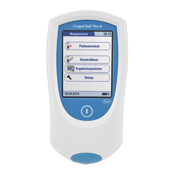
1.3 Overview of the meter elements ® CoaguChek Pro II · Operator’s Manual... - Page 30 Touchscreen Battery compartment cover Shows test results, information, icons, Remove to insert the battery pack and results recalled from memory. To select an option, simply touch the button lightly. On/Off button Charging contacts Press this button to power the meter on Used for power supply and/or charging or off.
-
Page 31: Buttons And Icons Overview
1.4 Buttons and icons overview The buttons and icons that appear during normal operation are shown here, along with their respective meanings. Button/Icon Meaning Go to Main Menu OK; save setting Cancel; discard setting Return (to previous menu) Decrease/increase the value displayed. Scroll through lists that are too long to be displayed all at once. - Page 32 Button/Icon Meaning Insert test strip Remove test strip Apply sample (the time left to apply sample is counted down in the display) Apply liquid control (QC) sample (the time left to apply sample is counted down in the display) Insert the test strip code chip Insert the QC code chip Automatic quality control completed successfully Results are displayed as a Quick percentage value...
- Page 33 Button/Icon Meaning Quality control: Result is below the specified range Battery status: ¾ Battery full: When the battery pack is fully charged, all segments are lit. ¾ Battery good: One missing segment indicates a partially charged battery pack. ¾ Battery half: Two missing segments indicate a partially charged battery pack.
- Page 34 The following icons may appear when using the meter in conjunction with a data management system (DMS). Button/Icon Meaning If displayed in the status bar: communication is taking place via the infrared interface. ¾ Last synchronization passed. ¾ Last synchronization failed. If displayed in the status bar: communication is taking place via WLAN.
-
Page 35: Power Supply
1.5 Power supply The CoaguChek Pro II meter is exclusively operated with the rechargeable battery pack. Always insert the battery pack, even when using the power adapter. This ensures smooth operation and prevents a loss of the date and time settings if the power goes out. The meter cannot be operated without a battery pack. - Page 36 r Dispose of used battery packs in an environmentally responsible manner in accordance with applicable local regulations and directives. See Infection by a potentially biohazardous instrument. Disposal of the system (20) ® CoaguChek Pro II · Operator’s Manual...
-
Page 37: Putting The Meter Into Operation
2 Putting the Meter into Operation Before using the meter for the first time, perform the following steps: 1. Install the battery pack 2. Connect the power adapter to charge the battery pack 3. Set the current date and time 4. -
Page 38: Installing Or Replacing The Battery Pack
2.1 Installing or replacing the battery pack When shipped, the battery pack is not installed in the CoaguChek Pro II meter. When the battery pack is not installed, the meter cannot be used. Unused battery packs lose their charge over time and have to be recharged before they can be used. - Page 39 r To install the battery pack 1 Using the starshaped screwdriver contained in the kit (or another appropriate starshaped screwdriver, ® e.g. Torx size T5), loosen the screws on the battery compartment cover until they are protruding about 4‑5 mm (2/10 in). 2 Hold the battery pack in your hand, with the wires and the plug pinched between your thumb and index finger.
- Page 40 After inserting a new battery pack, the meter powers on automatically. • The Roche logo is displayed. If the meter does not power on automatically, the battery pack may be empty. Connect the power adapter for a minimum of 30 minutes, then remove the plug and try to power the meter on.
- Page 41 1 To shut down the meter, remove the external power supply, press the On/Off button about 5 seconds and release the On/Off button as soon as the Roche logo is displayed and the meter beeps. If you press the On/Off button for too long, a meter reset will be triggered after about 12 seconds and...
- Page 42 2 Place the meter face down on a level surface. 3 Using the starshaped screwdriver contained in the kit (or another appropriate starshaped screwdriver, ® e.g. Torx size T5), remove the four screws holding the battery compartment cover in place. 4 Remove the battery compartment cover from the meter.
-
Page 43: Powering The Meter On And Off
3 To power the meter off after use, press the button for approximately 1 second. r To check the software version 1 After displaying the Roche logo, the meter briefly displays the Init (for “initialization”) screen. Here you can check which software version is currently running on your meter. - Page 44 Page intentionally left blank. ® CoaguChek Pro II · Operator’s Manual...
-
Page 45: Meter Setup
3 Meter Setup 3.1 Display of screen elements Buttons are screen prompts that cause something to Note on presentation of happen when touched. The names of all buttons are screen elements in this either shown as bold text or as the icon used on the manual button (e.g., for OK). - Page 46 If the meter did not automatically enter the Setup mode (e.g., after the battery pack was replaced), you can open the Setup Menu from the Main Menu. 1. Touch Setup to open the meter settings. 2. Select the relevant group of settings (see Settings summary following this section).
-
Page 47: Settings Summary
3.2 Settings summary The diagram below shows all of the setup areas that can be accessed on the meter. ® CoaguChek Pro II · Operator’s Manual... - Page 48 Group Subgroup Setting Values Contrast 0 – 10 (5 *) Screen Parameter Result Units PT INR * Configuration INR/SEC INR/%Q Parameter Activation PT * PT, aPTT Result Confirmation Enable Disable * Language Selection Čeština Dansk Deutsch English * Español Français Italiano Nederlands Norsk...
- Page 49 Group Subgroup Setting Values Time formats 24‑hour time format (24h) 12‑hour time format (12h) with am/pm * Options Sort Date/Time * Patient ID Patient Name Beeper Beeper Medium * High Key Click Off * Auto Off [minutes] 1 … (5*) … 10 Connection Off * Computer...
- Page 50 Group Subgroup Setting Values Delete Database Results Code Chip Data Entire Database Parameter Selection Enable Disable * Admin. Blank (Off) * ID Setup (Administrator) Operator (Operator List is optional) Inactive * Active Scan Only/Hidden list Patient No * Optional Required Scan Only/Hidden list QC Settings QC Range...
- Page 51 Group Subgroup Setting Values Number of strips Number of levels: 1/2 (For each option except “No”) QC Interval Settings Time of day First day of week STAT Test Config. Enable Disable * Quantity 2 Level QC Yes * Scan QC Material Optional * Scan Only General...
-
Page 52: Screen Setup
3.3 Screen setup The Screen setup area contains the options for changing the display. r To set the contrast Use the Contrast menu to adjust the display to your ambient light conditions and make it easier to read. 1 From the Main Menu, touch Setup to open the meter settings. - Page 53 r To configure an additional parameter In the Parameter Configuration menu you can set the units for the display of PT test results and activate additional test parameters on the meter. r To configure the results units for PT Use this setting to select the unit(s) in which the result is displayed.
- Page 54 5 Touch the button to select the unit of measure of choice. Your selection is now highlighted. 6 Touch to save this setting, or touch to exit this menu without saving any changes. The display automatically returns to the previous screen. r To activate an additional parameter Additional test parameters can be activated on the meter.
- Page 55 4 From the Parameter Configuration menu, touch Parameter Activation. 5 Insert the code chip from the new box of test strips. The new parameter will now be activated. 6 Touch to confirm the corresponding information message. The display automatically returns to the Parameter Configuration menu. If the Parameter Activation button is grayed out, all...
- Page 56 1 From the Main Menu, touch Setup to open the meter settings. 2 From the Setup Menu, touch Screen. 3 From the Screen menu, touch Result Confirmation. 4 Touch Enable or Disable. Your selection is now highlighted. 5 Touch to save this setting, or touch to exit this menu without saving any changes.
- Page 57 1 From the Main Menu, touch Setup to open the meter settings. 2 From the Setup Menu, touch Screen. 3 From the Screen menu, touch Language Selection. The current language setting is highlighted (white type on a blue background). You can select either: •...
- Page 58 r To set the date When you power on the meter for the first time (or after a long period without power), the input field for the date automatically appears first. The date (and time) must be entered before the meter can be used further.
- Page 59 4 From the Date/Time menu, touch Date. 5 Touch to set the year, then the month, then the day. 6 Touch to save this setting, or touch to exit this menu without saving any changes. The display automatically returns to the previous screen. If this setup menu appeared automatically after powering the meter on, you must touch complete the first date setting.
- Page 60 4 From the Date/Time menu, touch Time. 5 Touch to set the hours, then the minutes. 6 Touch to save this setting, or touch to exit this menu without saving any changes. The display automatically returns to the previous screen. If this setup menu appeared automatically after powering the meter on, you must touch complete the first time setting.
- Page 61 4 From the Date/Time menu, touch Format. The current settings are highlighted. You can select one of the following display formats: • Date: DD.MM.YYYY (Day.Month.Year), e.g., 29.05.2015 • Date: MM/DD/YYYY (Month/Day/Year), e.g., 05/29/2015 • Date: YYYY‑MM‑DD (Year‑Month‑Day), e.g., 2015‑05‑29 • Time: 24H or 12H 5 Touch the button with the display format of choice for date and time.
-
Page 62: Options Setup
3.4 Options setup r To set the sorting order of lists Sort refers to the order in which measured and stored results are displayed when you use the Review Results function of the CoaguChek Pro II meter. You can display stored results chronologically by date and time or by person, based on the Patient ID. - Page 63 4 Touch the button to select the Sort by option of choice. Your selection is now highlighted. Note: The sort option Patient Name is available only when used together with a patient list. Patient lists can only be created with a DMS. For more details see 7.1 Data handling (147) 5 Touch...
- Page 64 1 From the Main Menu, touch Setup to open the meter settings. 2 From the Setup Menu, touch Options. 3 From the Options menu, touch Beeper. The current setting is highlighted. 4 You may select from the following options for the Beeper: •...
- Page 65 r To enable the auto off option You can set up your CoaguChek Pro II meter so that it powers itself off automatically if it has not been used (no buttons touched or tests run) for a preselected time period. Use this feature to save power and extend the life of the battery pack.
- Page 66 5 Touch to select the time of choice in minutes or to switch the feature off. 6 Touch to save this setting, or touch to exit this menu without saving any changes. The display automatically returns to the previous screen. r To enable the connection option In the Connection menu you can configure the data exchange with external devices.
- Page 67 r To enable/disable the QR Code display 1 From the Connection menu (see section above), touch Code. To enable the connection option (66) 2 Touch to enable, or touch to disable QR code display. Your selection is now highlighted. 3 If you have enabled this feature, select the style of the QR code to be displayed: •...
- Page 68 If you are a customer or a 3rd party IT provider, and you are interested to use this feature, contact your local Roche Diagnostics representative for additional information. 4 Touch Plain...
- Page 69 using the URL transmission method. Contact your specialized service provider in order to exchange this information. • Key: This key is auto‑generated by the meter and is required to decrypt the QR code information. • Serial No.: The meter's serial number is required to map the test result to the encryption key.
- Page 70 same time. The option Computer or Computer/ Printer (when activated) can be used together with a DMS to set up: • operator lists, or • patient lists (lists of patients to be tested) This eliminates the need for manual entry of these data.
- Page 71 2 Touch to save this setting, or touch to exit this menu without saving any changes. The display automatically returns to the previous screen. Extended data handling functionality is dependent on the capabilities of the particular Data Management System (DMS) being used and may vary.
- Page 72 activates an end-to-end TLS tunnel from meter to DMS. This is the most effective measure to achieve secure communication. It is recommended to activate these configurations. 2 Touch to save this setting, or touch to exit this menu without saving any changes. The display automatically returns to the previous screen.
- Page 73 avoid the loss of stored test results, you can archive this data using a data management system and the optional Handheld Base Unit (see Chapter 7). 1 From the Main Menu, touch Setup to open the meter settings. 2 From the Setup Menu, touch Options. 3 From the Options menu, touch Database.
- Page 74 5 If you selected Delete Database, you may select from the following options depending on which type of data you would like to delete: • Results • Code Chip Data • Entire Database 6 Touch to return to the Result Retention screen.
- Page 75 4 From the 2nd Options menu, touch Parameter Selection. 5 Touch Enable to display the parameter selection screen prior to each test or touch Disable to have the meter select the parameter by reading the test strip information. 6 Touch to save this setting, or touch to exit this menu without saving any changes.
-
Page 76: Id Setup
3.5 ID setup Use the ID Setup menu to enter settings for user management and patient management. These settings are optional and set to Off/Inactive by default; the meter can be operated without these settings. There are three types of identification used with the meter: ¾... - Page 77 – require a unique Patient ID for every test. Patient lists created externally can also be transferred to the meter, enabling you to select a Patient ID for a test from these lists. For more details see Data handling. 7.1 Data handling (147) Operator IDs can be selected from a list (if available) or read by the barcode scanner on the side of the meter.
- Page 78 The Admin.ID must also be entered before you can delete or change the Admin.ID itself. If you forget the Admin.ID, contact your Roche Diagnostics representative. r To configure an Admin. ID 1 From the Main Menu, touch...
- Page 79 4 Using the keypad displayed on the screen, enter the Admin. ID of choice. The ID can consist of up to 20 characters. Pay close attention to the buttons you press, because the characters are not displayed on the screen. Asterisks are displayed instead (as if entering a password on a computer).
- Page 80 r To change an Admin. ID 1 From the Main Menu, touch Setup to open the meter settings. 2 From the Setup Menu, touch Setup. 3 Using the keypad displayed on the screen, enter the current Admin. ID. The ID Setup menu is displayed. The Admin.
- Page 81 3 Using the keypad displayed on the screen, enter the current Admin. ID. The ID Setup menu is displayed. The Admin. button is highlighted, which means an Admin. ID is active. 4 Touch Admin. 5 Immediately touch to close the keypad on the screen without entering a password.
- Page 82 r To activate an operator ID 1 From the Main Menu, touch Setup to open the meter settings. 2 From the Setup Menu, touch Setup. 3 From the ID Setup menu, touch Operator. 4 Touch the button with the setting of choice for setting up the Operator login.
- Page 83 Patient ID If you want to create a list of Patient IDs from which you can select a patient for testing, additional software (a data management system) and the Handheld Base Unit are required (see Data handling). 7.1 Data handling (147) In the default setting, input of Patient IDs is set to This means each test is simply assigned a consecutive number.
- Page 84 4 Touch the button with the setting of choice for setting up the Operator login. Your selection is now highlighted. 5 Touch to save this setting, or touch to exit this menu, without saving any changes. The settings for the option No are now completed. For the options Optional and Required, continue by selecting the input format.
-
Page 85: Qc Settings Setup
There are two options: ¾ Default Range: The meter displays the QC Range provided by Roche Diagnostics in the code chip. ¾ Custom Range: The option Custom Range lets the user define their own QC Range within the default range. - Page 86 meter, and Operator login is activated. These lists are only available in connection with a data management system. For more details see Data handling. 7.1 Data handling (147) With this option you can configure a continuous 2 Level QC 2‑level liquid quality control test, if the test has two levels.
- Page 87 1 From the Main Menu, touch Setup to open the meter settings. 2 From the Setup Menu, touch Settings. 3 From the QC Settings menu, touch Range. 4 From the QC Range menu, touch the button of the test parameter you wish to set. You may select from the following options: •...
- Page 88 If you selected Custom Range, the QC Range screen opens and offers you the following options: • Display target value (On/Off) • Deviation from target value (percentage value). QC Range (86) For the control solutions, the target value always comes from the information stored in the code chip. If you have chosen Custom Range, you can now...
- Page 89 If the Custom Range and Target Value are set to On, they appear in a line below the control test result in the QC test and QC memory screens. The target value (2.9) appears in front of the custom range. If the Display target value is set to Off, only the Custom Range is displayed below the control test result.
- Page 90 The lockout triggers are set once and are valid for all parameters. The events (time intervals, numbers) triggering the lockouts are counted individually for each parameter. The lockout triggers based on counters (number of hours or strips) can be reset at any time (before the counter reaches the limit) by performing a quality control test.
- Page 91 6 You may select from the following options: • New Code Yes/No (applies every time a new test strip lot is used). The general intervals are: • • Daily • Weekly • No. of Hours • No. of Strips 7 Touch the button with your chosen option when changing the test strip lot.
- Page 92 13 For every option except for No, you must now indicate the number of levels at which the quality control must be performed. 14 Touch to save this setting, or touch to exit this menu without saving any changes. The display automatically returns to the previous screen.
- Page 93 4 From the Lockouts menu, touch Operator Lockout. If this button is disabled (grayed out), either no operators have been set up or the Operator ID option has been deactivated. Note: The option of setting up an Operator Lockout is available only when operator lists are created on the DMS.
- Page 94 9 For every option except for No, you must now indicate the number of levels at which the quality control must be performed. 10 Touch to save this setting, or touch to exit this menu without saving any changes. The display automatically returns to the previous screen.
- Page 95 The setting for Time of day applies to all lockouts based on date intervals. The setting for First day of week applies to lockouts in weekly intervals only. 6 Touch to enter the desired time and day. 7 Touch to save this setting, or touch to exit this menu without saving any changes.
- Page 96 The number of STAT tests performed is counted per test parameter used. Once the maximum number of STAT tests has been reached, this parameter cannot be tested without performing a control test first. Other test parameters that have not yet reached this limit are still available.
- Page 97 2 Level QC With this option you can configure a continuous 2‑level quality control test, if the test has two levels. r To enable 2 level QC 1 From the Main Menu, touch Setup to open the meter settings. 2 From the Setup Menu, touch Settings.
- Page 98 Scan QC Material The barcode scanner of the CoaguChek Pro II meter can be used to scan barcodes from QC material vials. r To use the scan QC material option 1 From the Main Menu, touch Setup to open the meter settings. 2 From the Setup Menu, touch Settings.
-
Page 99: Diagnostics
3.7 Diagnostics Under Diagnostics, you will find information about the system, such as software version, number of data records stored, and configuration details. The diagnostics screens shown here are for illustration purposes only. The Information shown on your meter may differ. r To display the diagnostics screens 1 From the Main Menu, touch Setup... - Page 100 4 Use to toggle between the Wireless Setup screens. 5 In the diagnostics screen, touch to return to the previous menu. ® CoaguChek Pro II · Operator’s Manual...
-
Page 101: Testing A Blood Sample
4 Testing a Blood Sample 4.1 Important notes ¾ CoaguChek Pro II meter What you need: ¾ Test Strips with matching code chip (see section "What can the system do for you?") ¾ When testing with venous blood: – Standard blood collection device (syringe) ¾... - Page 102 Protection against infection: r When collecting samples always observe the general precautions and guidelines relating to blood sampling. Safety information (17) r Dispose of all test strips used for patient testing in accordance with the disposal policy of your laboratory or practice. Safety information (17) 8.2 Cleaning and disinfecting the meter (155) Never...
- Page 103 Getting a good capillary Prepare the selected blood collection site and obtain blood sample blood from the patient per facility policy. If no facility policy exists for obtaining capillary blood, follow these recommendations: ¾ Have the patient wash his or her hands in warm, soapy water.
- Page 104 For sample collection use a standard blood collection Getting a good result from venous whole blood device. Do not use anti‑coagulants (e.g., EDTA, citrate, fluoride, oxalate, or heparin) to collect the blood sample. Venous blood samples may be collected from a venous line. If venous samples are collected by venipuncture, note the following: ¾...
-
Page 105: Preparing To Test
4.2 Preparing to test r To prepare to test 1 Have the test strip container at hand. 2 Make sure that the code chip supplied with these test strips is at hand. Each box of test strips contains a code chip. The parameter, the number on the code chip and the number on the test strip container must match. - Page 106 • Each code chip belongs to a particular lot of test strips. Only remove the code chip when you are testing with test strips taken from a new pack. • Protect the code chip from moisture and equipment that produces magnetic fields. r To insert the code chip 1 Remove the old code chip, if one is inserted in the meter.
- Page 107 3 Slide the new code chip into the code chip slot (as shown) until you feel it snap into place. If the code chip is missing or incorrectly inserted, a corresponding error message appears in the display. See Chapter 9.1 Status / Error messages (169) r To power on the meter 1 Place the meter on a level, vibration‑free surface,...
- Page 108 4 If the function Operator ID is active, without operator list, you are now prompted to enter an Operator ID. • Enter the Operator ID using the keypad. Touch to move to the next screen. 5 Alternatively, the Operator ID can also be entered (5),(6) using the built‑in barcode scanner.
- Page 109 8 Enter the (optional) password. 9 After you enter the password, touch to log on. The Main Menu is displayed and you can start the test. 10 When you touch , the operator pick list is displayed again. 11 When the tests are completed or another operator wants to perform additional tests, touch Logout log out (this button is available only when the...
-
Page 110: Performing A Test
4.3 Performing a test r To perform a test 1 Check the battery level. • If the battery icon turns red (one bar remaining), there may not be enough power remaining for another test. • If there are no bars remaining in the battery icon, you cannot perform any more tests. - Page 111 as a STAT test (if this function is enabled and if there are still STAT tests available). In these cases a QC status screen will be displayed after touching Patient Test. For more details see STAT Test Configuration (95) 5 With patient list go to step 7. Without patient list, touch Patient Test.
- Page 112 8 Touch to display the entry of choice. Select the patient to be tested from the list. 9 If the patient is not in the list, touch to create a new entry. You must now enter a Patient ID using the keypad. Note: Extended data handling functionality and patient ID entry options are dependent on the capabilities of the particular Data Management...
- Page 113 If the Parameter Selection option is enabled in the meter settings, you are now prompted to select the parameter to be tested. The testing procedure for both parameters is similar. For illustration purposes testing with PT test strips is shown as an example. 11 Touch the button to select the parameter you want to use.
- Page 114 The hourglass icon shows that the test strip is warming up. When the warming‑up process is complete, a further beep (provided the beeper is enabled) indicates that you can now apply blood. The blood drop icon flashes to indicate that the meter is ready to perform the test and is waiting for blood to be applied.
- Page 115 2 CAUTION! Massage the lanced finger gently until a drop of blood is formed. Do not press or squeeze the finger. Apply the first drop of blood from the finger. Apply the blood directly from the finger to the semicircular, transparent sample application area on top of the test strip.
- Page 116 If too much blood has been applied (> 20 μL) the exterior of the meter and the test strip guide should be cleaned and disinfected. For additional information on sample collection see Getting a good result from venous whole blood (104) You hear a beep tone when you have applied enough blood (provided the Beeper is enabled).
- Page 117 3 Results that are above or below the measuring range are indicated by the symbols > (above) or < (below). • If a “C” is displayed along with the result: This may occur if the hematocrit value is very low or due to erroneous blood collection (e.g., wet hands).
- Page 118 2 If you reject a result, you must enter a comment with an explanation. If you reject the result, this test result is no longer displayed. However, the test entry is stored. If a “C” is displayed along with the result: This may occur if the hematocrit value is very low or due to erroneous blood collection (e.g., wet hands).
- Page 119 4 Once you have selected the desired comment(s), touch to return to the results screen. The printer icon only appears if the printer function is activated. Otherwise it is not displayed. Test results are also saved when the meter is powered off in the results screen or automatically powers off.
- Page 120 1 After the test result is displayed, touch . You will be prompted to remove the strip. 2 Remove the test strip from the meter. • Safety information (17) 3 Power the meter off. 4 Clean the meter if necessary. See Chapter 8, Maintenance and Care starting with 8.2 Cleaning and disinfecting the meter (155) r To perform a STAT test...
- Page 121 4 Perform the test. When a STAT test is performed, this information is stored with the result. The number of STAT tests allowed is reduced by 1. After all pending quality control tests are performed, the specified number of STAT tests is available again in case of a new lockout.
- Page 122 Page intentionally left blank. ® CoaguChek Pro II · Operator’s Manual...
-
Page 123: Control And Proficiency Testing
¾ An onboard quality control within every single test strip. Roche Diagnostics offers liquid quality controls for the CoaguChek Pro II system. These controls are designed to assist you in meeting regulatory compliance requirements at your facility. -
Page 124: Preparing To Perform A Liquid Quality Control Test
5.2 Preparing to perform a liquid quality control test Prepare for a liquid quality control test in the same way you would prepare to perform a test with a capillary blood sample. The only difference is the use of control solution instead of blood. r To prepare for a liquid quality control test 1 Have the test strip container at hand. - Page 125 6 Hold the dropper with the sealed dropper neck pointing upward, then cut off the end of the cap with scissors. Do not hold the dropper close to your face. To avoid loss of diluent, hold the dropper by the stem;...
- Page 126 10 Swirl the bottle using a circular motion to completely dissolve all of the control plasma inside. Do not shake the bottle or turn it on its side. Doing so can cause components in the control plasma to stick to the sides of the bottle. Please refer to the control solution package insert.
-
Page 127: Performing A Liquid Quality Control Test
5.3 Performing a liquid quality control test r To perform a liquid quality control test 1 Place the meter on a level, vibration‑free surface or hold it in your hand so it is roughly horizontal. 2 Power the meter on by pressing You can also power on the meter directly by inserting a test strip or connecting the power adapter. - Page 128 6 Touch Control Test. 7 In the QC Test menu, touch Control Test again. 8 Touch the button to select the parameter you want to use. 9 The test strip icon prompts you to insert a test strip. Remove a test strip from its container and close the container again with the stopper.
- Page 129 12 If you are using a new test strip lot and have not inserted the test strip code chip yet, you must do so now. Otherwise you cannot perform a quality control test. As with the test strips, a quality control code chip is also provided with the control solutions.
- Page 130 15 If you are using a new control solution, remove the strip code chip from the meter and insert the code chip that came with the control solution instead. If the code chips get mixed up, check the letter on the code chips to tell them apart.
- Page 131 17 Using the dropper, draw up the dissolved contents of the bottle. 18 Apply a single drop of control solution directly from the dropper to the semicircular, transparent sample application area on top of the test strip. Do not add more control solution. You hear a beep when you have applied enough control solution (provided the beeper is enabled).
- Page 132 Note: The arrow (next to the result) refers to the INR result only. If you have selected to display INR and %Quick or INR and seconds, the (up or down) arrow next to the result refers only to the INR value. Regardless of the Result Units PT settings, aPTT is always displayed in seconds.
- Page 133 26 Clean the meter if necessary (see Chapter 8, Maintenance and Care starting with 8.2 Cleaning and disinfecting the meter (155) 27 CAUTION! Dispose of controls and used test strips from control testing in accordance with the disposal policy of your facility. The control solution contains animal material, which should be considered as potentially infectious.
-
Page 134: Proficiency Testing
5.4 Proficiency testing Observe the applicable regulations and directives of the responsible regulatory agencies when performing proficiency tests. Proficiency tests are performed on samples whose values are unknown to the operator performing the test. These samples are provided by an external source, and the results should be forwarded to the appropriate source after completing the test. -
Page 135: Preparing To Perform A Proficiency Test
5.5 Preparing to perform a proficiency test You prepare for a proficiency test in the same way you would prepare to perform a test with a capillary blood sample. The only difference is the use of the proficiency sample supplied instead of blood from a patient. -
Page 136: Performing A Proficiency Test
5.6 Performing a proficiency test r To perform a proficiency test 1 Place the meter on a level, vibration‑free surface or hold it in your hand so it is roughly horizontal. 2 Power the meter on by pressing You can also power the meter on directly by inserting a test strip or connecting the power adapter. - Page 137 6 Touch Control Test. 7 Touch Proficiency Test. For proficiency testing, the test parameter information is read from the test strip. 8 The test strip icon prompts you to insert a test strip. Remove a test strip from its container and close the container again with the stopper.
- Page 138 11 Enter or scan the sample ID. The hourglass icon shows that the test strip is warming up. When the warming‑up process is complete, a further beep (provided the beeper is enabled) indicates that you can now apply the proficiency sample. The dropper icon flashes to indicate that the meter is ready to perform the test and is waiting for the sample to be applied.
- Page 139 You hear a beep when you have applied enough of the sample (provided the beeper is enabled). The dropper icon disappears and the test starts. 13 The result of the proficiency test is displayed, the comment Proficiency is automatically added. If you want to add further comments, touch .
- Page 140 Page intentionally left blank. ® CoaguChek Pro II · Operator’s Manual...
-
Page 141: Review Results (Memory)
6 Review Results (Memory) The CoaguChek Pro II meter can save 2000 patient test results as well as 500 liquid quality control tests to memory, together with respective time and date. In addition, up to 120 code chip records (contents of 60 test strip code chips and 60 control solution code chips) are stored. -
Page 142: Viewing Test Results
6.1 Viewing test results r To view test results 1 Place the meter on a level, vibration‑free surface, or hold it in your hand so it is roughly horizontal. 2 Power the meter on by pressing 3 Wait until the main menu is displayed. 4 Touch Review Results 5 Select the type of results you want to view. - Page 143 • If the sort order has been set to “Patient ID” or “Patient Name”, the patient result screen is shown directly. r Buttons used for displaying results The following buttons for general use are located in the views described below: •...
- Page 144 1 Touch to scroll to the entry of choice on the screen. 2 Touch the entry you want to open. The entry is displayed. 3 Touch . The results for the selected patient are displayed. If you choose to display patient‑related lists, you cannot filter a list by test parameters.
- Page 145 1 Touch to scroll to the entry of choice on the screen. 2 Touch the entry you want to open. The entry is displayed. ® CoaguChek Pro II · Operator’s Manual...
- Page 146 Page intentionally left blank. ® CoaguChek Pro II · Operator’s Manual...
-
Page 147: Extended Functionalities
Management System (DMS) being used and may vary. When used in conjunction with the Handheld Base Unit from Roche Diagnostics (available separately), the CoaguChek Pro II meter can conveniently connect to a data management system (DMS). The main advantages of such a connection between meter and DMS may include: ¾... - Page 148 The option of setting up an Operator Lockout is available only when operator lists are created on the DMS, stored in the meter, and Operator login is activated. See Operator login and Operator Lockout for more details. Operator ID (81) Operator Lockout (92) Computer (Setup option) For initial connection to a DMS, the ability to...
- Page 149 This first configuration is also available without a DMS. ¾ Operator is activated, there is no list available and the “List” feature is set to “hidden” (only possible with a DMS). Setting the "List" feature to "hidden" with the DMS automatically blocks the display of the meter's onscreen keypad as well.
- Page 150 ¾ The Patient ID is set to Optional or Required, and there is no list available: A Patient ID can be entered manually via the onscreen keypad or read in via a barcode scan. The Patient ID is stored with the test result. ¾...
- Page 151 Patient list validation Depending on DMS settings, you have the following options for patient list validation when working with Patient lists: ¾ A Patient ID does not have to be on the list to be used (only valid for validation mode “off”). ¾...
- Page 152 A.3 Supported characters in 2D barcodes (189) Stored test results and When performing a test, the test result will be stored comments along with additional information, including the Patient ID, Operator ID, the kind of test performed, and optional Comments. The meter comes with a default set of Comments that can be assigned to each test result.
-
Page 153: Maintenance And Care
8 Maintenance and Care 8.1 Conditions for storage and shipping ¾ Store the system and test strips in the same Storage environment in which they are used. ¾ Do not store the meter in direct sunlight or under extreme temperature conditions. ¾... - Page 154 Shipping r Observe the following safety information when shipping the meter and battery pack. Failure to do so may result in injury to persons or damage to the meter or battery pack. • If the meter is shipped or transported over long distances, always remove the battery pack from the meter.
-
Page 155: Cleaning And Disinfecting The Meter
8.2 Cleaning and disinfecting the meter r Observe the disinfection guidelines of your institution. r Protective gloves should always be worn when cleaning and disinfecting the device. NOTICE! Follow the procedures below to clean/disinfect the meter. Failure to follow these procedures may cause malfunction of the meter. - Page 156 Follow recommendations from the FDA, CDC and CMC and your facility’s policies and procedures for (9),(10) infection control. The FDA recommends that Point of Care testing devices should be used on one patient only and not shared. If it is not possible for each individual patient to have a dedicated POC device, the meters must be properly cleaned and disinfected after every use or before being used on the next patient, following the...
- Page 157 For technical assistance or questions on cleaning and disinfecting, please contact Roche Care Center at 1‑877‑273‑3433. ® CoaguChek Pro II · Operator’s Manual...
-
Page 158: Cleaning/Disinfecting The Exterior (Meter Housing)
If you notice any signs of deterioration after cleaning or disinfecting your meter, stop using it and contact Roche Care Center at 1‑877‑273‑3433 for assistance. Ensure that the blue test strip guide cover remains tightly closed while cleaning or disinfecting the exterior housing. - Page 159 r To clean/disinfect the exterior 1 Clean the exterior. With the meter powered off, wipe the meter’s ® exterior clean with a fresh Super Sani‑Cloth Germicidal Disposable Wipes. Remove any excess moisture from the the cloth before using it. Do not let liquid accumulate near any opening. Carefully wipe around the cover of the test strip guide and other openings.
- Page 160 instructed by the manufacturer in the product labeling. Always refer to the manufacturer’s labeling for contact time recommendations. 4 Dry the exterior. After the required contact time, dry the housing thoroughly with a dry lint‑free cloth. Visually verify that no residual moisture is seen anywhere on the meter at the completion of cleaning and disinfecting.
-
Page 161: Cleaning/Disinfecting The Test Strip Guide
8.4 Cleaning/disinfecting the test strip guide When to clean and disinfect the test strip guide ¾ The test strip guide should be cleaned and disinfected whenever the housing is cleaned and disinfected (see above). NOTICE! Damage to the instrument r Use only products containing the approved active ingredients. - Page 162 2 Clean the test strip guide cover. ® Clean the cover with a Super Sani‑Cloth Germicidal Disposable Wipe. After cleaning, dry the test strip guide cover thoroughly with a dry lint‑free cloth. 3 Clean the interior test strip guide Hold the meter upright with the test strip guide facing down.
- Page 163 After the required contact time, carefully dry the test strip guide cover with a dry lint‑free cloth. 5 NOTICE! Damage to the instrument Do not insert any objects into the test strip guide. Doing so could damage the electrical contacts behind the test strip guide.
- Page 164 anywhere on the test strip guide and cover at the completion of cleaning and disinfecting. Ensure that the test strip guide and cover are completely dry before assembling them. 7 WARNING! Re‑attach the test strip guide cover to the housing. Make sure that the cover is properly closed.
-
Page 165: Maintenance Cleaning Of The Interior Test Strip Guide In Case Of Residue
8.5 Maintenance cleaning of the interior test strip guide in case of residue build‑up When to clean the test strip guide ® Over time, the Super Sani‑Cloth Germicidal Disposable Wipes may leave a build‑up of residue in the test strip guide. ¾... - Page 166 2 Clean the interior test strip guide. Hold the meter upright with the test strip guide facing down. • Clean the easily accessible area (shown in the magnified illustration: white area below cotton swab and its black surrounding frame) with a water‑dampened cotton swab.
-
Page 167: Cleaning The Scanner Window
8.6 Cleaning the scanner window The scanner window should be cleaned periodically. Use a clean, dry cloth to wipe the scanner window. ® CoaguChek Pro II · Operator’s Manual... - Page 168 Page intentionally left blank. ® CoaguChek Pro II · Operator’s Manual...
-
Page 169: Troubleshooting
Take the action suggested on screen to resolve the problem. If the error disappears, you may continue using the meter as desired. If the problem persists, contact Roche Diagnostics. The two different message types are illustrated below: Message Description... - Page 170 If this error message appears again when the test is repeated, contact your local Roche representative. Possible reasons for this error message to appear again and again: ®...
- Page 171 ¾ The meter circuit board is defective. This can happen when, for example, cleaning and disinfecting agents enter the meter interior or when there are dried residues of cleaning and disinfecting agents in the meter interior. ¾ The test strip was wet or has already been used. ¾...
- Page 172 If this error message persists when the test is repeated, contact your local Roche representative. Additional information on error E‑406 E-406: Sample Error Error message Touch to exit this message. Perform the suggested step(s) to solve the problem. Power the meter off and remove the test strip. Repeat...
- Page 173 Errors and unusual error or status message. behavior without error messages If you notice any issues with the display functionality (e.g. unexpected lines/marks on the meter display), stop using the system and contact your Roche representative. ® CoaguChek Pro II · Operator’s Manual...
- Page 174 Message Description No message or unusual behavior • Wait 10 seconds and try powering on the Meter display does not power on meter again. • Check that the meter has power To install the battery pack (39) Is the battery pack properly installed in the meter? Does the meter power on when connecting the external power adapter?
- Page 175 Message Description This may occur if the test result is out of normal range. Touch the icon to display the Out Of Normal Range information screen. When interpreting results, refer to the detailed information on limitations and interferences included in the limitations section of the test strip package insert.
-
Page 176: Shut Down / Restart / Reset Meter
HBU 1 To shut down the meter, press the On/Off button for about 5 seconds and release the button as soon as the Roche logo is displayed and the meter beeps. The screen goes blank and the meter is shut down. - Page 177 • The meter powers off and on again. • The Roche logo is displayed. If the Roche logo does not appear within 60 seconds, place the meter in the Handheld Base Unit for a minimum of 15 minutes to recharge the battery.
- Page 178 4 Synchronize the meter’s date/time with the date/ time of your facility via the Handheld Base Unit or, if working wirelessly, wait at least ten minutes for the next WLAN synchronization before performing any further tests. Even if your configuration does not require it, we recommend always performing a QC test after a meter reset.
-
Page 179: General Product Specifications
10 General Product Specifications 10.1 Technical data Technical data Operating temperature range +12 °C to +32 °C (54 °F to 90 °F) Relative humidity 10 to 85 % (no condensation) Maximum altitude 4300 m (14,000 feet) Position Place the meter on a level, vibration‑free surface or hold it so it is roughly horizontal. Measuring range Refer to respective test strip package insert Memory... - Page 180 Storage conditions Temperature range Meter (without battery –5 °C to +45 °C (+23 °F to +113 °F) pack) Temperature range Meter (with battery –5 °C to +35 °C (+23 °F to +95 °F) pack) Relative humidity 10 to 85 % (no condensation) Transport conditions Temperature range Meter –25 °C to +70 °C (‑13 °F to +158 °F) (without battery pack) Temperature range Meter –10 °C to +70 °C (+14 °F to +158 °F)
-
Page 181: Further Information
Handheld Base Unit Kit Handheld Base Unit and Operator’s Manual Reagents and solutions Supplies are available through Roche Diagnostics. Contact your local Roche Diagnostics representative. Read the information in the package insert supplied Product limitations with the reagents and solutions for detailed product data and limitations. - Page 182 Roche Diagnostics representative. If you do not already have contact details, please visit our website at ¾ www.rochecanada.com or: ¾ www.coaguchek.ca. In Canada, the CoaguChek Pro II system is distributed Roche Diagnostics 201 Boul. Armand‑Frappier Laval, Québec (Canada) H7V 4A2 Telephone (region of Montréal): (450) 686‑7050...
-
Page 183: Warranty
11 Warranty The statutory guarantee provisions on rights in consumer goods sales in the country of purchase shall apply. ® CoaguChek Pro II · Operator’s Manual... - Page 184 Page intentionally left blank. ® CoaguChek Pro II · Operator’s Manual...
-
Page 185: Operator And Patient Id Barcode Masks
12 Appendix A A.1 Operator and patient ID barcode masks Barcode mask character Definition A‑Z, 0‑9 If not preceded by the Caret (“^”), the scan data character must be the same as the mask character. This character is not saved as part of the ID. If the characters are not the same, the scan data is not a valid ID. -
Page 186: Example Of Barcode Symbologies
A.2 Example of barcode symbologies If a barcode is read incorrectly, this may lead to patient misidentification and therefore to inappropriate therapy decisions. r When creating patient or operator barcodes, always adhere to the applicable international IEC/ ISO standards for the respective barcode symbology. - Page 187 WARNING! Avoidance of incorrect EAN 13 and Interleaved 2/5 barcode readings EAN 13 and Interleaved 2/5 barcodes, although widely used, are not recommended for patient/ operator barcodes. If an EAN 13 or Interleaved 2/5 barcode is read incorrectly, this may lead to patient misidentification and therefore to inappropriate therapy decisions.
- Page 188 Module width (minimum) 0.16 mm (linear barcodes) 0.20 mm (2D barcodes) Codabar Code 39 Code 93 Code 128 EAN 13 Interleaved 2/5 without checksum Interleaved 2/5 RSS (GS1 DataBar with checksum Limited) Aztec DataMatrix Roche Diagnostics Roche Diagnostics PDF417 QR Code Roche Diagnostics Roche Diagnostics ® CoaguChek Pro II · Operator’s Manual...
-
Page 189: Supported Characters In 2D Barcodes
A.3 Supported characters in 2D barcodes The 2D barcode scanner is able to read characters from the following unicode ranges: ¾ Basic Latin (0021‑007E) ¾ Latin-1 Supplement (00A1‑00FF) ¾ Latin Extended-A (0100‑017F) The 2D barcode scanner does not support Asian characters. ® CoaguChek Pro II ·... - Page 190 Page intentionally left blank. ® CoaguChek Pro II · Operator’s Manual...
-
Page 191: Supplement For Observed Test Sequence
13 Appendix B B.1 Supplement for Observed Test Sequence The Observed Test Sequence (OTS) function allows an Observed Test Sequence observer (supervisor) to assess and record an (OTS) operator’s performance (e.g., for recertification purposes). The observer monitors an operator during a test to check that the test is being performed according to the recommended procedures. -
Page 192: Using The Ots Function
Using the OTS function A request for an Observed Test Sequence comes from the DMS. The presence of the icon on the Patient Test button indicates a pending OTS request. r To log on as an observer during OTS 1 Touch Patient Test. - Page 193 r To log on as an operator during OTS 1 Touch Patient Test. Perform the patient test as usual. Once the test is completed, the observer has to complete the next steps. 2 Hand the meter back to the observer. r To perform tasks as an observer during 1 Touch to log in again.
- Page 194 7 Touch to return to the Main Menu. The OTS information is saved together with the test result. ® CoaguChek Pro II · Operator’s Manual...
-
Page 195: Option: Wireless Network (Wlan)
Meter with WLAN functionality 07210841190 For information on WLAN registration see addendum “WLAN registration information, Addendum to the Operator's Manual for the CoaguChek Pro II meter” at www.poc.roche.com (select the Products and Point of Care). The CoaguChek Pro II meter can only be configured Background through a data management system to communicate wirelessly. - Page 196 (16) to IEEE Standard 802.11 g (2.4 GHz range) . The system is backwards compatible to 802.11b. During wireless communication to an Access Point (AP), the CoaguChek Pro II meter recognizes the existent AP WLAN protocol configuration (802.11b or 802.11g) and automatically transmits data using the appropriate (17) communication protocol The loss of signal or access to bandwidth of one...
- Page 197 As part of an RF implementation of the CoaguChek Pro II system, it is recommended that at minimum one Handheld Base Unit be hard wired per floor. A networked Handheld Base Unit provides redundancy if a wireless network malfunctions or loses service. If the CoaguChek Pro II meter with RF is used in an area with low signal or interferences, it is recommended to install a connected Handheld Base Unit for...
- Page 198 The CoaguChek Pro II system offers the option of RF specific functionalities wireless network connectivity (WLAN/Wi‑Fi). and effective performance claims This module can only be configured by a data management system (DMS), which activates the meter’s wireless communication and data transfer capabilities.
- Page 199 infrastructure, DMS workload, etc. Once the DMS sends a query, however, the meter will respond within a few seconds. ¾ A CoaguChek Pro II meter with wireless connectivity enabled, communicates results after every test. When the meter is idle while docked, it automatically attempts to communicate with the DMS every 30 minutes.
-
Page 200: Index
Index Contrast ........52 Control solution Accessories. - Page 201 Meter – Overview ........29 Icons.
- Page 202 – Options ... 62, 63, 65, 66, 67, 69, 71 – Parameter selection ..... . . 74 QC Range .
- Page 203 Unit (test result) ......116 Units (of measure) ..... . 53, 54 Voltage.
- Page 204 Page intentionally left blank. ® CoaguChek Pro II · Operator’s Manual...
- Page 206 ACCU‑CHEK, COAGUCHEK and SAFE‑T‑PRO are trademarks of Roche. Distributed in Canada by: Roche Diagnostics 201 Boul. Armand‑Frappier Laval, Québec (Canada) H7V 4A2 Roche Diagnostics GmbH Sandhofer Strasse 116 68305 Mannheim, Germany www.rochecanada.com www.coaguchek.ca...
Need help?
Do you have a question about the CoaguChek Pro II and is the answer not in the manual?
Questions and answers
What is the difference between L1 and L2 IQC checks. Should we do both level checks each time or can we select one at randome ?
The Roche CoaguChek Pro II meter performs a continuous 2-level liquid quality control (IQC) test if the test has two levels (L1 and L2). The second test (L2) starts immediately after successfully completing the first test (L1). If this function is disabled, the meter returns to the Main Menu after one level is tested. This indicates that both levels are intended to be tested sequentially rather than selecting one at random.
This answer is automatically generated