Table of Contents
Advertisement
Quick Links
1.1 CP1484, CP1485, CP1486, CP3484, CP3485, CP3486
1.1.1 General information
Based on state-of-the-art Intel Celeron processor technology, the X20 CPUs cover a wide
spectrum of demands. They can be implemented in solutions ranging from standard applications
to those requiring the highest levels of performance.
USB and Ethernet are included in every CPU. Furthermore, every CPU has an ETHERNET
Powerlink connection for real-time communication.
In addition, there are up to three multi-purpose slots for additional interface modules.
•
Intel Celeron 650/400/266 Performance
•
Ethernet, ETHERNET Powerlink and USB onboard
•
Modular expansion of interfaces
•
Fan-free or exchangeable fan
•
Extremely compact
1.1.2 Order data
CP1484, CP1485, CP1486
Model number
X20CP1484
X20CP1485
X20CP1486
Data sheet V 1.00
CP1484, CP1485, CP1486, CP3484, CP3485, CP3486
1)
Short description
X20 CPU, Celeron 266 comp., 32 MB DRAM, 1 MB SRAM, exchangeable application memory:
CompactFlash, 1 insert slot for X20IF modules, 2 USB interfaces, 1 RS232 interface, 1 Ethernet
interface 10/100 Base-T, 1 ETHERNET Powerlink interface, order program memory separately.
X20 CPU, Celeron 400, 32 MB DRAM, 1 MB SRAM, exchangeable application memory:
CompactFlash, 1 insert slot for X20IF modules, 2 USB interfaces, 1 RS232 interface, 1 Ethernet
interface 10/100 Base-T, 1 ETHERNET Powerlink interface, order program memory separately.
X20 CPU, Celeron 650, 64 MB DRAM, 1 MB SRAM, exchangeable application memory:
CompactFlash, 1 insert slot for X20IF modules, 2 USB interfaces, 1 RS232 interface, 1 Ethernet
interface 10/100 Base-T, 1 ETHERNET Powerlink interface, order program memory separately.
Table 1: X20 CPUs - order data
CP3484, CP3485, CP3486
1)
1
Advertisement
Table of Contents

Related Manuals for ABB CP1484


Summary of Contents for ABB CP1484
- Page 1 CP1484, CP1485, CP1486, CP3484, CP3485, CP3486 1.1 CP1484, CP1485, CP1486, CP3484, CP3485, CP3486 1.1.1 General information Based on state-of-the-art Intel Celeron processor technology, the X20 CPUs cover a wide spectrum of demands. They can be implemented in solutions ranging from standard applications to those requiring the highest levels of performance.
- Page 2 CP1484, CP1485, CP1486, CP3484, CP3485, CP3486 Model number Short description X20CP3484 X20 CPU, Celeron 266 comp., 32 MB DRAM, 1 MB SRAM, exchangeable application memory: CompactFlash, 3 insert slots for X20IF modules, 2 USB interfaces, 1 RS232 interface, 1 Ethernet interface 10/100 Base-T, 1 ETHERNET Powerlink interface, order program memory separately.
-
Page 3: Technical Data
CP1484, CP1485, CP1486, CP3484, CP3485, CP3486 1.1.3 Technical data Product ID CP1484 CP3484 CP1485 CP3485 CP1486 CP3486 Short description System module Processor Celeron 266 comp. Celeron 400 Celeron 650 Interfaces 1 x RS232, 1 x Ethernet, 1 x ETHERNET Powerlink, 2 x USB... - Page 4 CP1484, CP1485, CP1486, CP3484, CP3485, CP3486 Product ID CP1484 CP3484 CP1485 CP3485 CP1486 CP3486 CPU and X2X Link supply Input voltage 24 VDC (-15 % / +20 %) Input current Max. 2.2 A Reverse polarity protection Fuse Integrated, cannot be exchanged...
- Page 5 CP1484, CP1485, CP1486, CP3484, CP3485, CP3486 Product ID CP1484 CP3484 CP1485 CP3485 CP1486 CP3486 Electrical isolation PLC - IF1/IF4/IF5 PLC - IF2/IF3 IF1/IF4/IF5 - IF2/IF3 IF1 - IF4/IF5 IF4 - IF5 Power consumption - without 10.5 W 10.5 W 10.5 W 10.5 W...
- Page 6 CP1484, CP1485, CP1486, CP3484, CP3485, CP3486 1.1.4 X20 CPUs - status LEDs Color Status Description Green Application running SERVICE mode RDY/F Yellow CPU is active Overtemperature Green/red Status/Error LED. The status of the LED is described in section "S/E LED".
- Page 7 CP1484, CP1485, CP1486, CP3484, CP3485, CP3486 ETHERNET Powerlink V1 Status LED Green Status of the Powerlink station The Powerlink station is running with no errors. A fatal system error has occurred. The error type can be read using the PLC logbook. It concerns an irreparable problem.
- Page 8 CP1484, CP1485, CP1486, CP3484, CP3485, CP3486 Green - status Description Single flash (approx. 1 Hz) The interface status is PRE_OPERATIONAL_1. PRE_OPERATIONAL_1 Managing Node (MN) The MN starts the operation of the "reduced cycle". Collisions are allowed on the bus. There is not yet any cyclic communication.
- Page 9 CP1484, CP1485, CP1486, CP3484, CP3485, CP3486 System halt error codes Incorrect configuration or defective hardware can cause a system halt error. The error is displayed via the red error LED using four switch-on phases. The switch-on phases are either 150 ms or 600 ms long. Error code outputs are repeated cyclically after 2 seconds has passed.
-
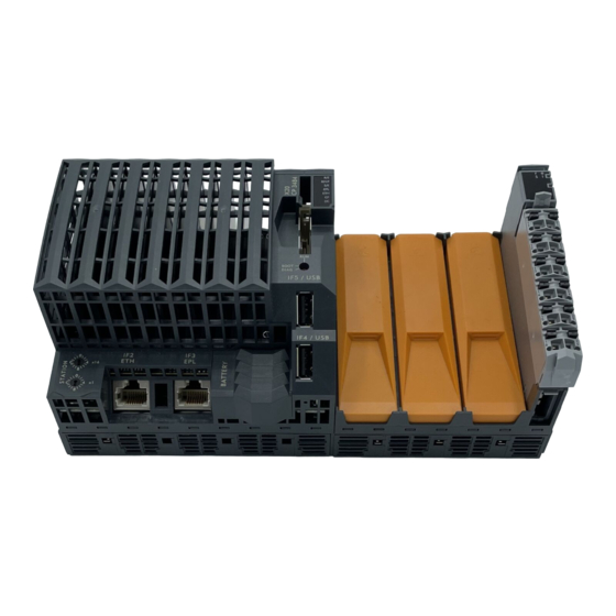
Page 10: Operating And Connection Elements
I/O feed, RS232 connection Ethernet IF2 - Ethernet Battery IF4 - USB Slots for station address IF3 - ETHERNET IF5 - USB interface Powerlink modules Figure 1: X20 CPUs - operating elements for CP1484, CP1485, and CP1486 Data sheet V 1.00... - Page 11 CP1484, CP1485, CP1486, CP3484, CP3485, CP3486 CP3484, CP3485, and CP3486 Mounting rail Operating mode latch switch CompactFlash LED status indicators IF1 - RS232 Exchangeable fan (CP3486) Ethernet IF2 - Ethernet Battery IF4 - USB Slots for Terminal block for CPU...
-
Page 12: Operating Mode Switch
CP1484, CP1485, CP1486, CP3484, CP3485, CP3486 1.1.8 Operating mode switch An operating mode switch is used to set the operating mode. Figure 3: X20 CPUs - operating mode switch Switch position Operating mode Description BOOT Boot In this switch position the default B&R Automation Runtime™ (AR) is started, and the runtime system can be installed using the online interface (B&R Automation Studio™). - Page 13 CP1484, CP1485, CP1486, CP3484, CP3485, CP3486 1.1.9 CPU supply A power supply comes integrated in the X20 CPUs. It is equipped with a feed for the CPU, the X2X Link, and the internal I/O supply. The feed to the CPU/X2X link supply is electrically isolated.
-
Page 14: Connection Examples
CP1484, CP1485, CP1486, CP3484, CP3485, CP3486 Connection examples With two separate supplies CP/X2X Link supply supply +24 VDC Figure 5: X20 CPUs - connection example with two separate supplies With a supply and jumper Jumper supply +24 VDC Figure 6: X20 CPUs - connection example with a supply and jumper... - Page 15 CP1484, CP1485, CP1486, CP3484, CP3485, CP3486 1.1.10 RS232 interface (IF1) The RS232 interface is not electrically isolated. It can be used as an online interface for communicating with the programming device. Figure 7: X20 CPUs - pin assignments - RS232 interface (IF1)
- Page 16 CP1484, CP1485, CP1486, CP3484, CP3485, CP3486 1.1.11 Ethernet interface (IF2) Figure 8: X20 CPUs - Ethernet interface (IF2) IF2 is an Ethernet interface. The connection is made using a 10/100 BASE-T Twisted Pair RJ45 socket. The INA2000 station number for the Ethernet interface is set with the two hex switches.
- Page 17 CP1484, CP1485, CP1486, CP3484, CP3485, CP3486 1.1.12 ETHERNET Powerlink Interface (IF3) The station number can be set using software. Station numbers are permitted between $00 and $FD. Switch position Description Operation as Managing Node (standard). $01 - $FD Station number for Powerlink station. Operation as controlled node.
- Page 18 CP1484, CP1485, CP1486, CP3484, CP3485, CP3486 1.1.13 USB interfaces (IF4 and IF5) Figure 10: X20 CPUs - USB interfaces (IF4 and IF5) IF4 and IF5 are USB interfaces. The connection is made using a USB 1.1 interface. The USB interfaces can only be used for devices which have been released by B&R (e.g. floppy disk drive, DiskOnKey or dongle).
- Page 19 CP1484, CP1485, CP1486, CP3484, CP3485, CP3486 1.1.15 Exchangeable fan The CPUs do not require a fan. The Celeron 650 CPU can optionally be fitted with a fan. This equips it for unrestricted use over the entire temperature range. Changing the fan 1) Press in fan lock with thumb and pull out fan.
- Page 20 CP1484, CP1485, CP1486, CP3484, CP3485, CP3486 1.1.17 Data / real-time buffering The CPUs are equipped with a backup battery. The following areas are buffered: • Remanent variables • User RAM • System RAM • Real-time clock Battery monitoring The battery voltage is checked cyclically. The cyclic load test of the battery does not considerably shorten the battery life, instead it gives an early warning of weakened buffer capacity.
-
Page 21: Procedure For Changing The Battery
CP1484, CP1485, CP1486, CP3484, CP3485, CP3486 Procedure for changing the battery 1) Touch the mounting rail or ground connection (not the power supply!) in order to discharge any electrostatic charge from your body. 2) Remove the cover for the lithium battery. To do this, slide the cover down from the CPU. - Page 22 CP1484, CP1485, CP1486, CP3484, CP3485, CP3486 4) Insert the new battery with correct polarity. To do this, the battery is laid with the "+" side up on the right part of the battery holder under the USB interface IF4. Then secure the battery in the holder by pressing above the left part of the battery holder.
- Page 23 CP1484, CP1485, CP1486, CP3484, CP3485, CP3486 5) A dialog box is displayed for configuring the runtime system version. The runtime system version is already preselected by the user's project settings. Using the drop-down menu, the runtime system versions stored in the project can be selected. Clicking on the Browse button allows the selected runtime system version to be loaded from the hard drive or from the CD.
- Page 24 CP1484, CP1485, CP1486, CP3484, CP3485, CP3486 5) A dialog box is displayed for configuring the runtime system version. The runtime system version is already preselected by the user's project settings. Using the drop-down menu, the runtime system versions stored in the project can be selected. Clicking on the Browse button allows the selected runtime system version to be loaded from the hard drive or from the CD.