Table of Contents
Advertisement
Quick Links
Advertisement
Table of Contents

Related Manuals for Mitsubishi Electric E70 Series


Summary of Contents for Mitsubishi Electric E70 Series
- Page 2 Introduction This manual is referred to when using the MITSUBISHI CNC E70 Series. This manual explains how to operate, run and set up this NC unit. Read this manual thoroughly before using the NC unit. To safely use this NC unit, thoroughly study the "Precautions for Safety" on the next page before use.
- Page 4 Precautions for Safety Always read the specifications issued by the machine tool builder, this manual, related manuals and attached documents before installation, operation, programming, maintenance or inspection to ensure correct use. Understand this numerical controller, safety items and cautions before using the unit. This manual ranks the safety precautions into "DANGER", "WARNING"...
- Page 5 For Safe Use Mitsubishi CNC is designed and manufactured solely for applications to machine tools to be used for industrial purposes. Do not use this product in any applications other than those specified above, especially those which are substantially influential on the public interest or which are expected to have significant influence on human lives or properties.
- Page 6 CAUTION [Continued] 4. Items related to screen operation If the tool compensation amount or workpiece coordinate system offset amount is changed during automatic operation (including during single block stop), the changes will be valid from the command in next block or after several subsequent blocks. All of the various data in the NC memory is erased when formatting.
- Page 7 CAUTION [Continued] 7.Items related to faults and abnormalities If the battery low warning is issued, save the machining programs, tool data and parameters in an input/ output device, and then replace the battery. When the battery alarm is issued, the machining programs, tool data and parameters may be destroyed.
- Page 8 Treatment of waste The following two laws will apply when disposing of this product. Considerations must be made to each law. The following laws are in effect in Japan. Thus, when using this product overseas, the local laws will have a priority.
- Page 10 This symbol mark is according to the directive 2006/66/EC Article 20 Information for end- users and Annex II. Your MITSUBISHI ELECTRIC product is designed and manufactured with high quality materials and components which can be recycled and/or reused. This symbol means that batteries and accumulators, at their end-of-life, should be disposed of separately from your household waste.
- Page 12 Trademarks MELDAS, MELSEC, EZSocket, EZMotion, iQ Platform, MELSOFT, GOT, CC-Link, CC-Link/LT and CC-Link IE are either trademarks or registered trademarks of Mitsubishi Electric Corporation in Japan and/or other countries. Ethernet is a registered trademark of Xerox Corporation in the United States and/or other countries.
- Page 14 本製品の取扱いについて ( 日本語 /Japanese) 本製品は工業用 ( クラス A) 電磁環境適合機器です。販売者あるいは使用者はこの点に注意し、住商業環境以外で の使用をお願いいたします。 Handling of our product (English) This is a class A product. In a domestic environment this product may cause radio interference in which case the user may be required to take adequate measures. 본...
-
Page 16: Table Of Contents
CONTENTS I SCREEN OPERATIONS 1 Operating the Setting and Display Unit ....................1 1.1 Display Unit and Keyboard Unit ......................2 1.2 Card Interface ............................5 1.2.1 Memory Card (Front IC Card) Interface ..................5 1.2.2 USB Memory..........................5 1.2.3 Caution ............................5 1.3 Screen Configuration .......................... - Page 17 2.5.1 Displaying the Machine Position Trace..................71 2.5.2 Canceling the Machine Position Trace ..................71 2.5.3 Changing the Display Range ....................... 72 2.5.4 Changing the Display Mode......................74 2.5.5 Changing the Display Angle......................75 2.5.6 Switching the Axis Movement Direction (+, -) ................75 2.5.7 Switching the Full-screen Display Mode ..................
- Page 18 3.5.3 Displaying the Life Management Data (L system: Tool life management I)....... 185 3.5.4 Displaying the Tool Life Management Data in Group Units (L system: Tool life Management II)................... 187 3.6 Workpiece Coordinate System Offset....................192 3.6.1 Setting the Coordinate System Offset Amount ................194 3.6.2 Erasing the Coordinate System Offset Amount .................
- Page 19 4.4.6 Changing a File Name (Rename) ....................274 4.4.7 Creating a Directory ........................275 4.4.8 Merging a File ..........................276 4.4.9 Formatting an External Device....................277 4.4.10 List of File Names ........................277 4.4.11 Edit Lock B and C ........................278 4.4.12 Program Display Lock C ......................
- Page 20 6.5.1 Adjustment Preparations......................389 6.5.2 Performing Automatic Adjustments.................... 390 6.5.3 Performing Manual Adjustments....................390 6.6 Absolute Position Setting Screen....................... 392 6.6.1 Selecting the Axis ........................394 6.6.2 Carrying Out Dogless-type Zero Point Initialization ..............395 6.6.3 Carrying Out Dog-type Zero Point Initialization................403 6.6.4 Precautions ..........................
- Page 21 6 Operation Panel Switch Functions......................23 6.1 Chamfering............................24 6.2 Miscellaneous Function Lock ....................... 24 6.3 Single Block ............................24 6.4 Z Axis Cancel ............................24 6.5 Dry Run ..............................24 6.6 Manual Override........................... 24 6.7 Override Cancel ........................... 24 6.8 Optional Stop ............................
- Page 22 7.2 Chuck Barrier/Tailstock Barrier (L System)..................64 7.2.1 Detailed Description........................64 7.2.2 Setting the Chuck Barrier/Tailstock Barrier.................. 65 7.2.3 Restrictions ..........................67 7.3 Manual Synchronous Tapping ......................68 7.3.1 Outline ............................68 7.3.2 Command Format ........................68 7.3.3 Operation Procedures........................68 7.3.4 Precautions ..........................
- Page 23 Appendix 6.6 Absolute Position Detection System Alarms (Z7*) ............. 100 Appendix 6.7 Distance-coded Reference Scale Errors (Z8*)..............103 Appendix 6.8 Emergency Stop Alarms (EMG)..................104 Appendix 6.9 Computer Link Errors (L)....................107 Appendix 6.10 User PLC Alarms (U) ....................... 108 Appendix 6.11 Network Service Errors (N) ....................
-
Page 24: I Screen Operations
I S C R E E N O P E R A T I O N S... -
Page 26: Operating The Setting And Display Unit
Operating the Setting and Display Unit I - 1... -
Page 27: Display Unit And Keyboard Unit
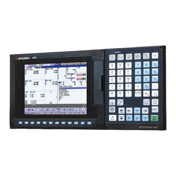
MITSUBISHI CNC 1 Operating the Setting and Display Unit This explains the operations and functions common to the screens. 1.1 Display Unit and Keyboard Unit Setting display device is structured by display unit and keyboard unit. A menu key is a part of display unit. Operations such as screen transition and data setting are to be made with keyboard unit or menu keys. - Page 28 E70 Series Instruction Manual 1.1 Display Unit and Keyboard Unit The following keys are provided on the keyboard. Some keyboards may not have the keys that are shown below. Key type Operation This displays the screen related to "operations". (MONITOR) (Refer to "2.
- Page 29 MITSUBISHI CNC 1 Operating the Setting and Display Unit Key type Operation This displays the operation guidance, parameter guidance and alarm guidance corresponding to the current operation. Help key Particular keys These key definitions differ according to the machine tool builder.
-
Page 30: Card Interface
E70 Series Instruction Manual 1.2 Card Interface 1.2 Card Interface There is a card interface on right side of display unit. It can use compact flash (CF) card and USB memory. 1.2.1 Memory Card (Front IC Card) Interface It can insert compact flash (CF) card. -
Page 31: Screen Configuration
MITSUBISHI CNC 1 Operating the Setting and Display Unit 1.3 Screen Configuration Display items Display item Details NC name The currently displayed NC name (name set in parameter "#1135 unt_nm") is displayed. This appears if a parameter requiring the power to be turned ON again has been changed. Power ON request This flickers at an approx. -
Page 32: Operation Mode
E70 Series Instruction Manual 1.3 Screen Configuration 1.3.1 Operation Mode The selectable operation mode is following below. Symbol Details Explanation MEMORY Memory operation Automatic operation is based on programs stored in the memory. Automatic operation is based on tape command (RS232C input) programs... -
Page 33: Alarms/Warnings
MITSUBISHI CNC 1 Operating the Setting and Display Unit 1.3.4 Alarms/Warnings When an alarm or warning occurs, the alarm No. and alarm message character string are displayed. (Example) Warning display S51 Parameter error Character color Background color Alarm White Warning Black Yellow The display format of PLC alarms and operator messages can be selected by the parameter "#11021 PLC mesg disp... -
Page 34: Screen Transition Diagram
Er Comp Er Comp Macro Posn timer timer counter constnt select param data list switch PLCIndx CC-Link CC-Link Refer to "6. Maintenance Screens" param param 1 param 2 Items with (*) are not available on E70 series. I - 9... -
Page 35: Screen Selection Procedure
MITSUBISHI CNC 1 Operating the Setting and Display Unit 1.5 Screen Selection Procedure The screen is selected by pressing a function key such as [MONITOR] or [SETUP], or by pressing a menu key displayed in the screen selection menu. Operation method (To display "T-ofs" screen from the "Setup screen") Press the function key [SETUP]. -
Page 36: Setting Data
E70 Series Instruction Manual 1.6 Setting Data 1.6 Setting Data 1.6.1 Setting Numerals and Alphabetic Characters Operation method The data is basically set with the following methods: (1) Menu selection (2) No. selection (3) Cursor movement (4) Data key input (5) [INPUT] key input (Note 1) The contents in the data setting area are only displayed until the [INPUT] key is pressed. - Page 37 MITSUBISHI CNC 1 Operating the Setting and Display Unit ■ [DELETE] key: Deletes the character in front of the cursor. Move the cursor to the position where the data is to The cursor moves in the data setting area. be deleted. 123777456 The character in front of the cursor is deleted, and the cursor Press the [DELETE] key.
-
Page 38: Inputting Operations
E70 Series Instruction Manual 1.6 Setting Data 1.6.2 Inputting Operations In addition to the method of directly inputting numeric data for specific data settings, a method to input the operation results using four rules operators and function symbols can be used. - Page 39 MITSUBISHI CNC 1 Operating the Setting and Display Unit Notes for using operators and functions Division : Zero division causes an error. Square root : If the value in the parentheses is negative, an error occurs. Triangle function : The unit of angle θ is degree (°). Arc tangent : -90 <...
-
Page 40: Operating The Screen
E70 Series Instruction Manual 1.7 Operating the Screen 1.7 Operating the Screen 1.7.1 Changing the Menu The menu can be used to select screens and to select functions or setting items. Up to ten menus can be displayed at once. -
Page 41: Menu List
MITSUBISHI CNC 1 Operating the Setting and Display Unit 1.8 Menu List The menu list is a function that displays each screen's menu configuration as a list. The Menu list window opens when the [MenuList] key is pressed on each screen. If a pop-up window other than the menu list is displayed, the Menu list window appears above the displayed pop-up window. - Page 42 E70 Series Instruction Manual 1.8 Menu List List of menu names (functions) Screen Menu name Outline Search Call a program for automatic operation. Reserch Restart machining from a selected block. Edit Edit the machining program searched for operation. Trace Trace the T path based on the machining program being executed.
-
Page 43: Displaying The Menu Function Outline
MITSUBISHI CNC 1 Operating the Setting and Display Unit 1.8.1 Displaying the Menu Function Outline Operation method The Menu list window appears showing the selected screen's Press the [MenuList] key. menu list at the top. When the [MenuList] key is pressed while editing the file on the Edit screen, a prompt to confirm whether to save the program appears before Menu list window opens. -
Page 44: Guidance Function
E70 Series Instruction Manual 1.9 Guidance Function 1.9 Guidance Function 1.9.1 Operation/Parameter Guidance The parameter/operation guidance function displays the details of the parameters or the operation methods according to the state of the screen currently being displayed. (Note) Depending on the specifications of the machine tool builder, it might not be displayed. - Page 45 MITSUBISHI CNC 1 Operating the Setting and Display Unit Displaying the operation guidance Press the [Edit] menu on operation screen. The edit window is displayed. The guidance window is opened, and sub-contents for edit Press the [?] key. operation method is displayed. (Note) If the explanation of operation method is nothing, the contents list is displayed.
- Page 46 E70 Series Instruction Manual 1.9 Guidance Function Displaying the parameter guidance Press the [Param] menu on maintenance screen. The machining parameter screen is displayed. Press the [ ↓ ] key, and move the cursor to "#8005 ZONE r" parameter. The guidance window is opened, and the detail of "#8005 Press the [?] key.
- Page 47 MITSUBISHI CNC 1 Operating the Setting and Display Unit Displaying the operation guidance by selecting the contents Press the [Search] menu on operation screen. The operation search window is displayed. The parameter/operation guidance window is opened, and Press the [?] key. sub-contents for operation search is displayed.
- Page 48 (6) When power supply is turned off guidance data will be deleted. (7) The instructions of parameter/operation guidance are commonly used for M700V, M70V, and E70 series. This manual is written on the assumption that all option functions are added. Confirm with the specifications manual issued by the machine tool builder before starting use.
-
Page 49: Alarm Guidance
MITSUBISHI CNC 1 Operating the Setting and Display Unit 1.9.2 Alarm Guidance The alarm guidance is the function that displays message, details and remedy for the currently occurring alarms. (Note) Depending on the specifications of the machine tool builder, it might not be displayed. Screen configuration The alarm guidance is displayed in "alarm"... - Page 50 E70 Series Instruction Manual 1.9 Guidance Function Operation method If the [?] key is pressed on any screen, the alarm guidance window will open. If a pop-up window other than the alarm guidance window is open, the alarm guidance window will open over the currently opened pop-up window. In this case, the menu state does not change.
- Page 51 (3) The alarm guidance of stop code and operator message is not displayed. (4) The instructions of alarm guidance are commonly used for M700V, M70V, and E70 series. This manual is written on the assumption that all option functions are added.
-
Page 52: Screen Saver (Backlight Off) Function
E70 Series Instruction Manual 1.10 Screen Saver (Backlight OFF) Function 1.10 Screen Saver (Backlight OFF) Function The screen saver function protects the display unit by backlight OFF after the time set in the parameters has elapsed. The backlight can also be turned OFF with key operations on the Monitor screen. -
Page 53: Backlight On
MITSUBISHI CNC 1 Operating the Setting and Display Unit 1.10.2 Backlight ON If a key is pressed or the screen display request signal is input while the backlight is OFF, the backlight will be turned Key operation The correspondence when the key is pressed is as follows during backlight OFF. (1) Backlight ON + screen transition (Example) Function key, [?] key, etc. -
Page 54: Screen Capture
E70 Series Instruction Manual 1.11 Screen Capture 1.11 Screen Capture When "1" is set to the parameter "#8121 Screen Capture", and then [SHIFT] key is kept pressing for about 3 seconds until the buzzer sounds the screen information displayed in the display unit can be output to USB memory or memory card (CF) as a file of the bitmap format. -
Page 55: Menu Customization Function
MITSUBISHI CNC 1 Operating the Setting and Display Unit 1.12 Menu Customization Function This function allows to change the display order of monitor, setup and edit screen. This function enables to place the often-used keys in the first page. It can be used when a parameter "#11032 Menu sel para lkof Validate menu selection parameter setting" is set to "2". Machine tool builder's password is required when it is set to "1". - Page 56 E70 Series Instruction Manual 1.12 Menu Customization Function Precautions (1) If a menu No. for not to display the main menu is set to the menu selection parameter, it will not be displayed. Menu which is set with other menu non-display parameter (“#8923 Hide Edit-IO menu”, “#8932 Hide measure scrn”) will also not be displayed even if it is set with the menu selection parameter.
- Page 57 MITSUBISHI CNC 1 Operating the Setting and Display Unit I - 32...
-
Page 58: Monitor Screens
Monitor Screens I - 33... - Page 59 MITSUBISHI CNC 2 Monitor Screens Various information related to operation, such as the axis counter, speed display and MSTB command are displayed on the Monitor screen. The following operations regarding operation can be executed. (1) Operation search (2) Restart search (3) Editing the searched machining program (4) Trace (Display of machine movement path) (5) Check (Display of NC program's tool movement path)
-
Page 60: Screen Configuration
E70 Series Instruction Manual 2.1 Screen Configuration 2.1 Screen Configuration "Auto/MDI" and "Manual" are displayed at the upper left of the screen. These displays change according to the mode selection switch. <For Auto/MDI> 8.4-type (10) (11) <For Manual> 8.4-type (10) - Page 61 MITSUBISHI CNC 2 Monitor Screens Display items Display item Details This displays the counter of the relative position and workpiece coordinates positions, etc. If each axis is in a specific position or status, the following status symbol appears. #1 to #4 : No. 1 to No. 4 reference position ][ : Servo OFF state MR : Mirror image ><...
- Page 62 E70 Series Instruction Manual 2.1 Screen Configuration Display item Details Machining program currently being executed (Note) (10) Main This displays the program No., sequence No. and block No. currently being executed. When a subprogram is being executed, this displays the subprogram's program No., 01234 sequence No.
- Page 63 MITSUBISHI CNC 2 Monitor Screens Menu Details Reference This displays the common variables. 2.16 Common A value can also be set for the common variable. Variables This displays the local variables. 2.17 Local Variables This corrects the buffer. 2.18 Buffer Correction 2.19 PLC Switch This turns the PLC switches ON or OFF.
-
Page 64: Counter Display
E70 Series Instruction Manual 2.1 Screen Configuration 2.1.1 Counter Display The counter display contents are as follows. (1) Auto/MDI <8.4-type> Layout Display Remarks Relative position This can be changed with "#8901 counter type 1". Program position This can be changed with "#8902 counter type 2". -
Page 65: Switching The Counter Types
MITSUBISHI CNC 2 Monitor Screens 2.1.2 Switching the Counter Types When Manual display or enlarged counter is selected ("#8909 Aut/Manual switch"="3"), it is possible to change counter types to display with the tab keys ([|<-] / [->|]). In Manual display, with the tab keys, the counter displayed at the left (the counter set by the parameter "#8905 Counter type 5") is switched. -
Page 66: Changing Between
E70 Series Instruction Manual 2.1 Screen Configuration 2.1.3 Changing Between <Auto/MDI> and <Manual> The correspondence between the mode selection switch settings and display contents on the left side of the screen is as follows. #8909 Aut/Manual switch Mode selection switch setting...And -
Page 67: Operation Search
MITSUBISHI CNC 2 Monitor Screens 2.2 Operation Search On this screen, the program can be called from the program storage site, such as a memory, by designating the program (program No.) to be automatically run and the program start position (sequence No., block No.). Display items Display item Details... - Page 68 E70 Series Instruction Manual 2.2 Operation Search Menus Menu Details Type Reference Memory This selects the device for searching for the program. 2.2.1 Executing an Serial When a device with directory is selected, the route is selected first. Operation Search...
-
Page 69: Executing An Operation Search
MITSUBISHI CNC 2 Monitor Screens 2.2.1 Executing an Operation Search Operation method The sub-menu appears. Press the main menu [Search]. The list appears as a pop-up window. Select the device. The selected device name and route directory (memory card) (Example) [Memory card] appear in the Device name, Directory display field. -
Page 70: Changing Whether To Show Or Hide The Comment Field
E70 Series Instruction Manual 2.2 Operation Search 2.2.2 Changing Whether to Show or Hide the Comment Field The file name field can be extended by changing whether to show or hide the comment field. Operation method The file name is displayed up to 32 alphanumeric characters Press the menu [Comment nondisp]. -
Page 71: Changing The Sorting Method
MITSUBISHI CNC 2 Monitor Screens 2.2.3 Changing the Sorting Method Sorting method changes to 1 → 2 → 3 → 4 → 5 → 1……every time the [Sort change] menu is pressed. The selected sorting method is also displayed in the list on the ther screens. The method is common for all the devices, as well. -
Page 72: Restart Search
E70 Series Instruction Manual 2.3 Restart Search 2.3 Restart Search If machining is temporarily stopped due to tool breakage, etc., the program restart function searches for the block of the machining program to be restarted, and restarts machining from that block. - Page 73 MITSUBISHI CNC 2 Monitor Screens Screen transition <Top search screen> (Note) [Top search] [Search exec] / [Top search] / [INPUT] / <Main screen> <File setting screen> [File set] [Retn] / File input operation / <MSTB History screen> [MSTB history] [MSTB history] / (Note) In the following cases, the screen cannot be switched to top search screen.
- Page 74 E70 Series Instruction Manual 2.3 Restart Search Precautions (1) Set the tool offset amounts and parameters before proceeding the program restart search. If they are not set beforehand, the axes will not return to the proper machining start position. (2) Attempting the automatic start up during the restart search causes "T01 Cycle start prohibit 0111" and it will not start up automatically.
-
Page 75: Main Screen
MITSUBISHI CNC 2 Monitor Screens 2.3.1 Main Screen The type 1 and type 2 restart search can be executed from the Main screen. Display items Display item Details Device and directory This displays the device and directory where the searched machining program is located. display This displays the researched main program position (program No., sequence No., block Research position... - Page 76 E70 Series Instruction Manual 2.3 Restart Search Menus Menu Details Type Reference This starts the restart search based on the designated device, directory, Search program number (O), sequence number (N), block number (B) and number exec of block execution times (P).
-
Page 77: Top Search Screen
MITSUBISHI CNC 2 Monitor Screens 2.3.2 Top Search Screen Display items Same as "2.2 Operation Search". Menus Menu Details Type Reference This starts the restart search based on the designated device, directory, Search program number (O), sequence number (N), block number (B) and number exec of block execution times (P). -
Page 78: File Setting Screen
E70 Series Instruction Manual 2.3 Restart Search 2.3.3 File Setting Screen Display items Same as "2.2 Operation Search". Menus Menu Details Type Reference Memory Select the device to search program. When a device other than memory is selected, the root is selected first. -
Page 79: Mstb History Screen
MITSUBISHI CNC 2 Monitor Screens 2.3.4 MSTB History Screen Display items Display item Details The M, S, T and B command used in the machining program are listed. Up to 35 M commands, 3 commands each for S1 to S6, 3 T commands and 3 B commands MSTB history are displayed. -
Page 80: Operation Sequence For Program Restart
E70 Series Instruction Manual 2.3 Restart Search 2.3.5 Operation Sequence for Program Restart There are two types of restart, type 1 and type 2. Restart type 1 When feed hold has been applied and reset because the tool has broken, etc., restart with Restart type 1. - Page 81 MITSUBISHI CNC 2 Monitor Screens Restart type 2 If a machining program differing from the machining program to be restarted was run before starting restart search, restart with restart type 2. When the coordinate system of the automatic operation last time and the coordinate system of the machining restart are changed, it is possible to restart.
-
Page 82: Executing Restart Search (Restart Type 1)
E70 Series Instruction Manual 2.3 Restart Search 2.3.6 Executing Restart Search (Restart Type 1) When feed hold has been applied and reset because the tool has broken, etc., restart with Restart type 1. Operation method (Example) When tool breakage during execution of O1000 N7 occurred, and restarting from the O1000 N6 block Press the feed hold button and retreat to the tool change position by manual means or MDI. -
Page 83: Executing Restart Search (Restart Type 2)
MITSUBISHI CNC 2 Monitor Screens 2.3.7 Executing Restart Search (Restart Type 2) If a machining program differing from the machining program to be restarted was run with tape, memory or HD operation before starting restart search, restart the respective machining program with restart type 2. The restart type 2 operation sequence is the same as restart type 1, but necessary matters for starting the machining program, such as setting the coordinate system, must be completed before starting restart search. -
Page 84: Changing The Device
E70 Series Instruction Manual 2.3 Restart Search Operation method (When the parameter "#8914 Auto Top search" is "1") (Example) When restarting from subprogram O123 N6 B2 called from main program O1000 Turn the power ON, and return all axes to the reference position. -
Page 85: Changing The Directory With The Main Screen
MITSUBISHI CNC 2 Monitor Screens 2.3.9 Changing the Directory with the Main Screen Operation method Press the submenu [File set]. The window for file setting appears as a pop-up window. PAGE Using the [ ↑ ],[ ↓ ], keys, move the The following is displayed. - Page 86 E70 Series Instruction Manual 2.3 Restart Search (Note 1) When the restart switch is ON, move the axis in the same direction as the restart direction. If moved in the reverse direction, the operation error "M01 R-pnt direction illegal" occurs. If the tool needs to be retracted once, such as if the tool is interfering with the workpiece, turn the restart switch OFF and retract the axis manually.
- Page 87 MITSUBISHI CNC 2 Monitor Screens Automatic restart position return If the parameter "#1302 AutoRP" is set to "1", each axis returns to the restart position with dry run at cycle start. Machining restarts after returning. The order that the axes return follows parameter "#2082 a_rstax". (Note 1) Manually move the axis to a position where the tool does not interfere with the workpiece before starting the cycle.
-
Page 88: Executing The Mstb Commands
E70 Series Instruction Manual 2.3 Restart Search 2.3.11 Executing the MSTB Commands If the MSTB history menu is pressed after restart search is completed, the MSTB commands used for machining program appear. When the cursor is moved to the listed M, S, T, B commands and the [INPUT] key is pressed, that command will be executed. -
Page 89: Program Edit
MITSUBISHI CNC 2 Monitor Screens 2.4 Program Edit The machining programs are edited. When the main menu [Edit] is pressed, or turn ON the "Edit/Search" signal, the operation searched program (MDI program for MDI mode) appears. If no program has been searched or tape operation has been executed, the edit window will not open. When the program is edited, the key input data is directly written into the program display area. -
Page 90: Edit/Search Window
E70 Series Instruction Manual 2.4 Program Edit 2.4.1 Edit/Search window By turning ON/OFF the edit/search signal, the operation search is carried out starting from the block that has the cursor. There are 2 ways to implement cursor position search: "INPUT search" and "Edit/Search signal search". When the status is automatic operation, checking, or restart search, cursor position search cannot be operated. - Page 91 MITSUBISHI CNC 2 Monitor Screens Operation method(Edit/Search signal search) It is valid if "2" or "3" is set to parameter "#11031 Cursor pos search". Carry out the operation search to find the program to carry out the cursor position search. Turn ON the edit/search signal.
- Page 92 E70 Series Instruction Manual 2.4 Program Edit Operation method (search during single block stop) Cursor position search can be operated during single block stop when parameter "#11039 Cusr pos srch Tyoe" is "1".By pressing [Edit] menu during single block stop, single block stop position becomes top of the program display.
-
Page 93: Trace
MITSUBISHI CNC 2 Monitor Screens 2.5 Trace This function illustrates the actual machine's movement path or tool center point movement path, and draws the actual machine movement. This allows the machine operation to be monitored during machining. The programs that can be traced are operation searched machining programs (MDI program for MDI mode). If no program has been operation searched, the trace window will not open. - Page 94 E70 Series Instruction Manual 2.5 Trace ■ Full-screen display ([All display] is ON) < Drawing area > Display items Display item Details The counter of the axis targeted for the trace drawing is displayed. The three axes which are displayed are set with the parameters.
- Page 95 MITSUBISHI CNC 2 Monitor Screens Menus Menu Details Type Reference This activates the trace mode. If any program is currently running, the machine 2.5.1 Displaying the Trace position path is traced from the current position. If this menu is pressed during Machine Position Trace the machine position trace mode, the trace mode will be turned OFF.
-
Page 96: Displaying The Machine Position Trace
E70 Series Instruction Manual 2.5 Trace 2.5.1 Displaying the Machine Position Trace Operation method Press the main menu [Trace ON]. - The [Trace ON] menu is highlighted. - The machine position appears in the drawing area as a tool mark. -
Page 97: Changing The Display Range
MITSUBISHI CNC 2 Monitor Screens 2.5.3 Changing the Display Range The graphic drawing's scale can be enlarged or reduced, and the position moved or centered. Operation method (Enlarging the and reducing the drawing) A white frame indicating the display range appears on the Press the [Display range] key. - Page 98 E70 Series Instruction Manual 2.5 Trace (Note 1) When changing the display range in the 2-plane display mode such as "XY/XZ", the display range (scale and display position) for the upper and lower areas changes in the same manner. The operation method is the same as the 1-plane display mode.
-
Page 99: Changing The Display Mode
MITSUBISHI CNC 2 Monitor Screens 2.5.4 Changing the Display Mode The graphics display mode includes the 1-plane, 2-plane and 3D mode. When the menu [Display mode] is pressed and the following display mode menu is selected, the axis configuration of each plane changes, and the menu display returns to the original state. -
Page 100: Changing The Display Angle
E70 Series Instruction Manual 2.5 Trace Operation method (Changing the display axis name) Press the menu [Display mode]. The menus for the selectable display modes appear. The input area appears. Set the axis name, and press the [INPUT] key. XYC appears as the axis name in the display mode. -
Page 101: Switching The Full-Screen Display Mode
MITSUBISHI CNC 2 Monitor Screens 2.5.7 Switching the Full-screen Display Mode Press the [All display] menu key to display the trace window on the whole screen. (full-screen display mode). Press this menu again to return the normal display. Switching the display mode All display menu : ON All display... -
Page 102: Program Check (2D)
E70 Series Instruction Manual 2.6 Program Check (2D) 2.6 Program Check (2D) Program check (2D) is a function that draws the machining program movement path without executing automatic operation. The machining program can be checked with graphic data drawn at a high speed. -
Page 103: Counter All-Axis Display
MITSUBISHI CNC 2 Monitor Screens 2.7 Counter All-axis Display A counter for all axes opens as a pop-up display. The type of displayed counter can be selected with the menu. I - 78... - Page 104 Close This closes the pop-up window and quits this function. Tip wk In E70 series, this menu cannot be selected. posn In E70 series, this menu cannot be selected. machine Pulse In E70 series, this menu cannot be selected.
-
Page 105: Tool Compensation Amount
MITSUBISHI CNC 2 Monitor Screens 2.8 Tool Compensation Amount The tool compensation data can be set and displayed. The tool compensation data screen configuration differs according to the tool compensation type. Refer to section "3.2 Tool Compensation Amount" for details. [Tool compensation type I (M system)] Parameter "#1037 cmdtyp"... - Page 106 E70 Series Instruction Manual 2.8 Tool Compensation Amount [Tool compensation type II (M system)] Parameter "#1037 cmdtyp" = 2 The shape compensation amount and wear compensation amount are set separately. The shape compensation amount is furthermore divided into length and radius dimensions.
- Page 107 MITSUBISHI CNC 2 Monitor Screens [Tool compensation type III (L system)] Parameter "#1037 cmdtyp" = 3 The wear data, tool length data and tool nose data are set separately. These are changed with the sub-menu. (a) Wear data Set the tool nose wear amount for each tool used. When the tool offset No. is designated by the tool command (T command), compensation is carried out matching the tool length data and tool nose data.
- Page 108 E70 Series Instruction Manual 2.8 Tool Compensation Amount Tool nose data Set the tool nose radius value (tool nose R), wear radius value (R wear) and tool nose point (tool nose point P) of the tool nose mounted on the tool for each tool used. When the tool offset No. is designated by the tool command (T command), offset is carried out matching the tool length data and tool nose data.
-
Page 109: Workpiece Coordinate System Compensation
MITSUBISHI CNC 2 Monitor Screens 2.9 Workpiece Coordinate System Compensation The coordinate system offset can be set and displayed. 6 sets of standard workpiece coordinate system offset and 48 sets of extended workpiece coordinate offset can be used. Refer to "3.6 Workpiece Coordinate System Offset" for details. (Note 1) The G92/G52 coordinate system offset cannot be set. -
Page 110: Counter Setting
E70 Series Instruction Manual 2.10 Counter Setting 2.10 Counter Setting An arbitrary value can be set in the relative position counter which opens as a pop-up window. The counter cannot be set for an axis of auxiliary axis state. Menus... - Page 111 MITSUBISHI CNC 2 Monitor Screens Operation method The relative position counter opens as a pop-up window. Press the main menu [Counter set]. The cursor appears at the 1st axis of the relative position counter. Instead of the operation above, the axis name The relative position counter opens as a pop-up window.
-
Page 112: Origin Set, Origin Cancel
E70 Series Instruction Manual 2.11 Origin Set, Origin Cancel 2.11 Origin Set, Origin Cancel Origin set and origin cancel can be executed. Origin set and origin cancel cannot be executed for an axis of auxiliary axis state. Menus Menu Details... - Page 113 MITSUBISHI CNC 2 Monitor Screens Operation method (Setting the origin) The relative position counter opens as a pop-up window. Press the main menu [G92 set]. The menu [Origin set] is highlighted. The cursor appears at the 1st axis of the relative position counter.
-
Page 114: Manual Numerical Value Command
E70 Series Instruction Manual 2.12 Manual Numerical Value Command 2.12 Manual Numerical Value Command The spindle function (S), miscellaneous function (M), tool function (T) and 2nd miscellaneous function (B) commands can be executed. The manual numerical value command can be executed by inputting an address such as S, M, T or B, as well. - Page 115 MITSUBISHI CNC 2 Monitor Screens Operation method (Executing T31 with a manual numerical value command) Press the main menu [MST]. The S, M, T, B display opens as a pop-up window. M 50 B 1000 Using the [ ↑ ] and [ ↓ ] keys, move the cursor to The cursor moves.
-
Page 116: Modal Display
E70 Series Instruction Manual 2.13 Modal Display 2.13 Modal Display The state of each modal during automatic operation is displayed. The displayed details differ for the M system and L system. <M system> (1) (2) (4) (5) ... - Page 117 MITSUBISHI CNC 2 Monitor Screens Display items This displays each modal state. Display item Details Gxx…Gxx Status of currently executed G command modal Gxx…Gxx G50:P= Scaling magnification G54.1:P Extended workpiece coordinate system G69:R= Coordinate rotation angle (Displays within a ±360° range) G40: Tool radius compensation modal Offset No.
- Page 118 E70 Series Instruction Manual 2.13 Modal Display <L system> (10) (11) (12) (13) Display items This displays each modal state. Display item Details Gxx…Gxx Status of currently executed G command modal Gxx…Gxx G54.1:P Extended workpiece coordinate system The total value of the first axis' tool length and wear compensation amount for the tool being...
-
Page 119: Program Tree Display
MITSUBISHI CNC 2 Monitor Screens 2.14 Program Tree Display This displays the main program, subprogram, MDI interrupt and user macro call nesting structure. This also displays the execution position of the main program and the subprogram (the lowest level of the nest only) as a percentage during the automatic operation. -
Page 120: Integrated Time Display
E70 Series Instruction Manual 2.15 Integrated Time Display 2.15 Integrated Time Display The integrated time (date, time, power ON time, automatic operation time, automatic start time, external integrated time 1, external integrated time 2, cycle time) controlled by the NC can be set and displayed. -
Page 121: Setting The Integrated Time
MITSUBISHI CNC 2 Monitor Screens Menus Menu Details Type Reference Time 2.16.1 Setting the This sets the integrated time. setting Integrated Time Time The time that is displayed in upper line on cycle time display area is select1 selected. 2.16.2 Setting the Time Display Selection Time The time that is displayed in bottom line on cycle time display area is... -
Page 122: Setting The Time Display Selection
E70 Series Instruction Manual 2.15 Integrated Time Display 2.15.2 Setting the Time Display Selection The displayed time is set on cycle time display area. Operation method The time selection mode is activated, and the following menu Press the menu "Time select1"... -
Page 123: Common Variables
MITSUBISHI CNC 2 Monitor Screens 2.16 Common Variables The details of the common variables can be set and displayed on this screen. If there is a common variable command (Note) in the machining program, the variable value (variable name) set when the block is executed is displayed. - Page 124 E70 Series Instruction Manual 2.16 Common Variables Menus Menu Details Type Reference This executes an absolute input. =Input If "#8930 Disable=INPUT:var" is set to "1", this menu cannot be selected. This executes an addition input. +Input 2.16.1 Setting Common Variables This designates the variable No.
-
Page 125: Setting Common Variables
MITSUBISHI CNC 2 Monitor Screens 2.16.1 Setting Common Variables Operation method (Setting "135.000" in variable No. 102) Press the menu [Variabl No]. The menu is highlighted. Designate the variable No. The common variable for the set No. appears at the head. 102 [INPUT] The cursor can be moved to 102 using the [ ↑... -
Page 126: Erasing Common Variables
E70 Series Instruction Manual 2.16 Common Variables 2.16.3 Erasing Common Variables Operation method (Erasing the variable value for variable number 102 to 104) Press the menu [Variabl clear] . The menu is highlighted. A message confirming the erasing appears. Input the No. (range) of the variable to be erased. -
Page 127: Local Variables
MITSUBISHI CNC 2 Monitor Screens 2.17 Local Variables The details of the local variables are displayed Local variables 1 to 33 are prepared for each user macro subprogram call level. Up to 33 local variable data items are displayed on one level. A 5-level configuration from level 0 to level 4 is used in page order. If there is a local variable command or an argument designation called by the user macro subprogram in the block, and that block is executed first, the set variable value (variable name) will be displayed. - Page 128 E70 Series Instruction Manual 2.17 Local Variables Menus Menu Details Type Reference Display This lowers the local variable display level one by one. If this menu is level- pressed when the display level is 0, the level changes to display level 4.
-
Page 129: Displaying The Arbitrary Local Variables
MITSUBISHI CNC 2 Monitor Screens 2.17.1 Displaying the Arbitrary Local Variables Operation method (Displaying the next level) When the current display level is 0 Press the menu [Display level + ]. The level 1 local variables appear from the head. When the menu [Display level + ] is pressed again, the display level changes in the order of 2 →3→4→0→1→2→…... -
Page 130: Buffer Correction
E70 Series Instruction Manual 2.18 Buffer Correction 2.18 Buffer Correction During automatic operation (Memory, memory card) or MDI operation, a block stop can be applied, and the next command can be corrected or changed. When a program error occurs, the block in which the error occurred can be corrected without resetting the NC, and operation can be continued. - Page 131 MITSUBISHI CNC 2 Monitor Screens Menus Menu Details Type Reference Close This closes the pop-up window and quits this function. Operation method During a single block stop or when a program error stop occurs, the buffer can be corrected with the following operations, and operation can be continued.
- Page 132 E70 Series Instruction Manual 2.18 Buffer Correction Precautions (1) Buffer correction mode will not be applied in the following cases. (a) Machining program for buffer corrections is in edit lock or program display lock state. (b) Data protection key 3 is enabled.
- Page 133 MITSUBISHI CNC 2 Monitor Screens (5) Previous command and command in execution (a) When the buffer is corrected following the operation mode change at single block stop, nothing will be displayed in previous command and command in execution. (b) When there is no block after sub program call or user macro call, a program error occurs at the last block of the destination program.
-
Page 134: Plc Switch Function
E70 Series Instruction Manual 2.19 PLC Switch Function 2.19 PLC Switch Function The various control signals for NC operation can be turned ON and OFF. Refer to the instruction manual issued by the machine tool builder for details. Display items... -
Page 135: Turning Plc Switches On/Off
MITSUBISHI CNC 2 Monitor Screens 2.19.1 Turning PLC Switches ON/OFF Operation method (To turn switch "#6 Program restart" ON) The menu Setting valid will be highlighted. Press the menu [Setting valid] . A message confirming the start of PLC switch setting will appear. -
Page 136: Load Meter Display
E70 Series Instruction Manual 2.20 Load Meter Display 2.20 Load Meter Display The spindle load and Z axis load, etc., are displayed. Display items Display item Details Load meter 1 The spindle load and Z axis load, etc., are displayed in a bar graph. -
Page 137: Spindle, Standby Display
MITSUBISHI CNC 2 Monitor Screens 2.21 Spindle, Standby Display The current spindle tool No. and the standby tool No. are displayed. Display items Display item Details Spindle standby The display contents differ depending on machine tool builder specification. This displays No. of tool that is attached to the spindle or standby position. Tool No. -
Page 138: All Spindles' Rotation Speed Display
E70 Series Instruction Manual 2.22 All Spindles' Rotation Speed Display 2.22 All Spindles' Rotation Speed Display The current spindle tool No. and the standby tool No. are displayed. This function only displays the value. It is not possible to operate here. - Page 139 MITSUBISHI CNC 2 Monitor Screens I - 114...
-
Page 140: Setup Screens
Setup Screens I - 115... -
Page 141: Screen Configuration
MITSUBISHI CNC 3 Setup Screens The setup screen is used to make tool and workpiece related settings, set user parameters, edit the MDI, set the counter, and perform manual numerical value commands. 3.1 Screen Configuration The setup screen is configured as shown below. Display items Display item Details... - Page 142 E70 Series Instruction Manual 3.1 Screen Configuration Menus Menu Details Reference This sets the tool compensation amount. There are three types of tool compensation, and the display differs for each type. 3.2 Tool Compensation The number of tool compensation combinations are 200 sets on M system and 80 amount sets on L system.
-
Page 143: Tool Compensation Amount
MITSUBISHI CNC 3 Setup Screens 3.2 Tool Compensation Amount The tool compensation data can be set and displayed. The tool compensation data screen configuration differs according to the tool compensation type. Tool compensation combinations are 200 sets on M system and 80 sets on L system. Inputting an address key, such as MST, displays manual numerical value command window where manual numerical value command is executed. -
Page 144: Tool Compensation Amount (M System)
E70 Series Instruction Manual 3.2 Tool Compensation Amount 3.2.1 Tool Compensation Amount (M system) [Tool compensation type I] : Parameter "#1037 cmdtyp" = 1 The combined amount of the shape compensation and wear compensation are set as the compensation data, with no distinction between shape compensation memory and wear compensation memory. - Page 145 MITSUBISHI CNC 3 Setup Screens CAUTION If the tool compensation amount or workpiece coordinate system offset amount is changed during automatic operation (including during single block stop), the changes will be valid from the command in the next block or after several subsequent blocks. Display items Display item Details...
- Page 146 E70 Series Instruction Manual 3.2 Tool Compensation Amount Menus Menu Details Type Reference This executes an absolute input. When "#8929 Disable=INPUT : comp" is set to "1", this menu cannot be =Input selected. 3.2.1.1 Setting the Tool Compensation Data This executes an addition input.
-
Page 147: Setting The Tool Compensation Data
MITSUBISHI CNC 3 Setup Screens 3.2.1.1 Setting the Tool Compensation Data Operation method (Setting "37.000" in the length wear data of offset No. (102)) Press the menu key [Offset No.] Designate the offset No. The set number appears at the top of the area, and the cursor moves. - Page 148 E70 Series Instruction Manual 3.2 Tool Compensation Amount Operation method ("-3.000" is calculated and set in the length wear data for offset No. (102).) Use the same procedure as (1) above to move the cursor to the offset No. 102 length wear position.
-
Page 149: Switching The Input Method For The Tool Compensation Data
MITSUBISHI CNC 3 Setup Screens 3.2.1.2 Switching the Input Method for the Tool Compensation Data When a parameter "#8941 ABS/INC for T-ofs" is set to "1", the absolute/addtion input by the [INPUT] key can be switched. When attempting to switch it, the current input mode is displayed on the upper left of the tool compensation amount. -
Page 150: Erasing The Tool Compensation Data
E70 Series Instruction Manual 3.2 Tool Compensation Amount 3.2.1.3 Erasing the Tool Compensation Data Operation method (Erasing one line of tool compensation data at the cursor position) Move the cursor to the line to be erased with the [ ↑... -
Page 151: Copying/Pasting The Tool Compensation Data
MITSUBISHI CNC 3 Setup Screens 3.2.1.4 Copying/Pasting the Tool Compensation Data Operation method (Copying/pasting one line of tool compensation data) Move the cursor to the line to be copied with the [ ↑ [ ↓ ], keys. Press the [Line copy] menu. The background color of the copied data changes to light blue. -
Page 152: Tool Compensation Amount (L System)
E70 Series Instruction Manual 3.2 Tool Compensation Amount 3.2.2 Tool Compensation Amount (L system) 3.2.2.1 Wear Data Set the tool nose wear amount for each tool used. When the tool offset No. is designated by the tool command (T command), compensation is carried out matching the tool length data and tool nose data. - Page 153 MITSUBISHI CNC 3 Setup Screens Display items Display item Details Displays the tool compensation data. The displayed cursor can be moved and data set. Data that cannot be displayed in the display area can be displayed using the keys below. : Scroll one line at a time.
- Page 154 E70 Series Instruction Manual 3.2 Tool Compensation Amount Menus Menu Details Type Reference 3.2.2.4 Operation This executes an absolute input. =Input Method (1) Setting the Tool This executes an addition input. +Input Compensation Data This changes to the wear data display.
-
Page 155: Tool Length Data
MITSUBISHI CNC 3 Setup Screens 3.2.2.2 Tool Length Data Set the tool length in respect to the program basic position of each tool used. When the tool offset No. is designated by the tool command (T command), compensation is carried out matching the wear data and the tool nose data. CAUTION If the tool compensation amount or workpiece coordinate system offset amount is changed during automatic operation (including during single block stop), the changes will be valid from the command in the next... - Page 156 E70 Series Instruction Manual 3.2 Tool Compensation Amount (Note 1) The display and setting ranges are as follows based on the "#1003 iunit"and "#1041 I_inch" setting combination. #1003 iunit #1041 I_inch Setting/display range -9999.999 to 9999.999 - 999.9999 to 999.9999 -9999.9999 to 9999.9999...
-
Page 157: Tool Nose Data
MITSUBISHI CNC 3 Setup Screens 3.2.2.3 Tool Nose Data Set the tool nose radius value (tool nose R), wear radius value (R wear) and tool nose point (tool nose point P) of the tool nose mounted on the tool for each tool used. When the tool offset No. is designated by the tool command (T command), compensation is carried out matching the tool length data and tool nose data. - Page 158 E70 Series Instruction Manual 3.2 Tool Compensation Amount Tool nose point (Note 1) The setting and display ranges are as follows based on the "#1003 iunit(Input unit)"and "#1041 I_inch(Initial state (inch))" setting combination. #1003 iunit #1041 I_inch Setting/display range -9999.999 to 9999.999 - 999.9999 to 999.9999...
-
Page 159: Operation Method
MITSUBISHI CNC 3 Setup Screens 3.2.2.4 Operation Method (1) Setting the Tool Compensation Data Operation method (Setting "18.000" in the X-axis tool nose wear compensation amount of offset No. (1)) Press the menu key [Offset No.] The set number appears at the top of the area, and the cursor Designate the offset No. - Page 160 E70 Series Instruction Manual 3.2 Tool Compensation Amount Operation method ("-2.000" is calculated and set in the X-axis tool nose wear compensation amount for offset No. (102).) Use the same procedure as (1) above to move the cursor to the offset No. 1 X-axis length wear position.
- Page 161 MITSUBISHI CNC 3 Setup Screens Operation method (Erasing the compensation data from offset No. 1 to 3.) Press the [Line clear] menu. The menu is highlighted. A message box displays to confirm whether it is okay to erase Input the offset No. of the data range to be erased. the data.
-
Page 162: Disabling The Setting Of Tool Compensation Amount
E70 Series Instruction Manual 3.2 Tool Compensation Amount 3.2.2.5 Disabling the Setting of Tool Compensation Amount Depending on the setting of the parameter "#8933 Disable lngth comp"/"#8934 Disable wear comp", the setting of the shape compensation amount/wear compensation amount is disabled. -
Page 163: Tool Measurement
MITSUBISHI CNC 3 Setup Screens 3.3 Tool Measurement 3.3.1 Tool Measurement (M system) By manually moving the tool to the measurement point, the movement distance from the basic point to the measurement point is measured, and this can be set as the tool compensation amount. Inputting an address key, such as MST, displays manual numerical value command window where manual numerical value command is executed. - Page 164 E70 Series Instruction Manual 3.3 Tool Measurement ■ Tool length measurement II When the tool is at the machine coordinate zero point, the distance from the machine coordinate zero point to the tool tip is measured, and can be set as tool compensation data.
- Page 165 MITSUBISHI CNC 3 Setup Screens Display items Display item Details Manual measurement This displays the manual measurement status. status display Refer to the "Manual measurement status display" section for further details. TLM value : This displays the value during measurement. This will be the same as the machine position until the sensor is contacted.
- Page 166 E70 Series Instruction Manual 3.3 Tool Measurement Menus Menu Details Type Reference This writes the value displayed in "Mea value" as the tool compensation amount. The wear amount is cleared to "0" for the tool compensation type II. The tool compensation amount cannot be written in when the menu [Offset No.] or [Surface hight] is highlighted.
- Page 167 MITSUBISHI CNC 3 Setup Screens Carrying out tool length measurement Turn ON the measurement switch. The message "On mea 0" appears. Refer to the PLC Interface Manual for details on measurement switch signals. The menu is highlighted, and the tool length measurement Press the [T-leng measure] menu.
- Page 168 E70 Series Instruction Manual 3.3 Tool Measurement Manual measurement status display The display will change as shown below during manual measurement. Display Meaning This state is entered if a skip signal is input during manual measurement. On mea 1 The "On mea 2" state is shifted to after deceleration stop is confirmed.
-
Page 169: Tool Measurement (L System)
MITSUBISHI CNC 3 Setup Screens 3.3.2 Tool Measurement (L system) This is used to carry out manual tool length measurement I or II. Either one is selected depending on the setting of measurement switch and operation mode. Inputting an address key, such as MST, displays manual numerical value command window where manual numerical value command is executed. - Page 170 E70 Series Instruction Manual 3.3 Tool Measurement <Parameter selection method> When the parameter "#1282 ext18/bit2" is "0", the measurement point will be the point offset by the amounts set in the parameter "2015 tlml-" from the machine coordinate origin. The tool length will be automatically calculated by the method shown below.
- Page 171 MITSUBISHI CNC 3 Setup Screens (2) Measurement value input method (#1102 tlm = 1) Actually cut the workpiece. Measure its dimensions, and obtain the tool length from the measured values. Set the measurement basic point beforehand. The measurement basic point is either a point specific to machines (center of chuck face, etc.) specified by the parameter "# 2015 tlml-"(the center of the chuck face, etc.) or the workpiece coordinate offset (modal), which is specified by parameter "#1282 ext18/bit2 (tool length measurement 1 measurement basic point selection)".
- Page 172 E70 Series Instruction Manual 3.3 Tool Measurement <Parameter selection method> When the parameter "#1282 ext18/bit2" is "0", the measurement point will be the point offset by the amounts set in "#2015 tlml-" from the machine coordinate system origin. The tool length will be automatically calculated by the method shown below.
- Page 173 MITSUBISHI CNC 3 Setup Screens <Workpiece coordinate system offset selection method> When the parameter "#1282 ext18/bit2" is "1", the measurement point will be the point offset by the workpiece coordinate system offset (modal). The tool length will be automatically calculated by the method shown below. Tool length = Measurement value(workpiece coordinate position) - Workpiece measurement value (Note 1) As for the workpiece measurement value, set the diameter value for the diameter command, and set the...
- Page 174 E70 Series Instruction Manual 3.3 Tool Measurement ■ Manual tool length measurement II By using a device having a touch sensor, the tool compensation amount can be calculated just by contacting the tool nose against the touch sensor with manual feed.
- Page 175 MITSUBISHI CNC 3 Setup Screens Tool compensation amount = Machine coordinate position (machine coordinate position at the time of skip input) - Measurement basic position (sensor position) The expression above is used for automatic calculation in Manual tool length measurement II. Tool length basic point X-axis...
- Page 176 E70 Series Instruction Manual 3.3 Tool Measurement ■ Screen image [Manual tool length measurement I: Basic point method] (a) Normal operation mode (b) Simple operation mode I - 151...
- Page 177 MITSUBISHI CNC 3 Setup Screens [Manual tool length measurement I: Measurement value input method] (a) Normal operation mode (b) Simple operation mode (1) (2) I - 152...
- Page 178 E70 Series Instruction Manual 3.3 Tool Measurement [Manual tool length measurement II] Display items Display item Details When "Manual tool length measurement 1", the measurement result and measurement axis are displayed. The display timing and measurement result differ, depending on whether the basic point method or measurement value input method is selected.
- Page 179 MITSUBISHI CNC 3 Setup Screens Display item Details This displays the measurement image. The contents of the guide drawing will differ depending on the tool measurement type. <Manual tool length measurement I: Basic point method> <Manual tool length measurement I: Measurement value input method> Guide drawing <Manual tool measurement II>...
- Page 180 E70 Series Instruction Manual 3.3 Tool Measurement Menus(Manual tool length measurement 1 (normal operation mode) and Manual tool length measurement 2) Menu Details Type Reference Depending on the mode, the following value is input as the tool compensation amount at the cursor position, and the wear amount is cleared to "0".
- Page 181 MITSUBISHI CNC 3 Setup Screens Menus (Manual tool length measurement 1(Simple operation mode)) Menu Details Type Reference This displays the operation message "Input offset No". Input an offset No. and press the [INPUT] key. The following value is written as the tool compensation amount, and which item to write is determined by the selected mode.
- Page 182 E70 Series Instruction Manual 3.3 Tool Measurement Menu Details Type Reference Cancels displaying the values at "Measure value" and "Work meas". The cursor moves from "Work meas" to the tool compensation data. Cancel If any mode other than"Manual tool length measurement I: Measurement value value input method"...
- Page 183 MITSUBISHI CNC 3 Setup Screens (b) Simple operation mode 1 If the parameter "#8957 T meas (L)-Simple mode" is set to "1", designate the offset No. to write the compensation amount when pressing the [Offset write] menu. (Example) Carrying out tool measurement for offset No.4, X axis and Z axis Select the tool to be measured with a manual The tool to be measured is selected.
- Page 184 E70 Series Instruction Manual 3.3 Tool Measurement (c) Simple operation mode 2 When the parameter "#8957 T meas (L)-Simple mode" is "2", the compensation amount is written to the offset No. of the cursor position at the time of the [Offset write] menu pressed.
- Page 185 MITSUBISHI CNC 3 Setup Screens (Note 3) When the parameter "#8924 Meas. confirm msg" is "1", the [Offset write] menu is highlighted and the confirmation message "OK? (Y/N)" appears. By pressing [Y] (or [INPUT]) key at this time, the measurement value is written as the tool compensation amount, the highlight of the [Offset write] menu is canceled and the operation message is cleared from the screen.
- Page 186 E70 Series Instruction Manual 3.3 Tool Measurement Carrying out tool measurement (Manual tool length measurement I: Measurement value input method) (a) Normal operation mode (Example) Carrying out tool measurement for offset No.3, X axis Select the tool to be measured with manual The tool to be measured is selected.
- Page 187 MITSUBISHI CNC 3 Setup Screens (b) Simple operation mode 1 If the parameter "#8957 T meas (L)-Simple mode" is "1", designate the offset No. to write the compensation amount when pressing the [Offset write] menu. (Example) Carrying out tool measurement for offset No.3, X axis and Z axis Select the tool to be measured with a manual The tool to be measured is selected.
- Page 188 E70 Series Instruction Manual 3.3 Tool Measurement To set the measurement results of the other axes, repeat (6). The value "5" is set to the 2nd line of "Work meas". Example) 5 [INPUT] (Note 1) Compensation amount is written in diameter value for diameter command, or in radius value for radius command.
- Page 189 MITSUBISHI CNC 3 Setup Screens (c) Simple operation mode 2 When the parameter "#8957 T meas (L)-Simple mode" is "2", the compensation amount is written to the offset No. of the cursor position at the time of the [Offset write] menu pressed. (Example) Carrying out tool measurement for offset No.3, X axis and Z axis.
- Page 190 E70 Series Instruction Manual 3.3 Tool Measurement To set the measurement results of the other axes, The measure value is memorized. repeat (3) to (6). The memorized value is displayed in "Measure value", and the cursor moves to the selected axis (Z axis) of the "Work meas".
- Page 191 MITSUBISHI CNC 3 Setup Screens (Note 4) When the parameter "#1124 ofsfix" is "0", the cursor moves to the next offset No. However,when "#1124 ofsfix" is "1", the cursor does not move to the next offset No. (Note 5) When the parameter "#11017 T-ofs set at run" is "1", the tool compensation amount data can be set even during automatic operation or operation pause.
-
Page 192: Tool Registration
E70 Series Instruction Manual 3.4 Tool Registration 3.4 Tool Registration A tool No. is assigned to each tool to make the tools installed on the machine recognizable to the NC. The tool No. is registered corresponding to the magazine pot and spindle where that tool is installed, and the standby location. - Page 193 MITSUBISHI CNC 3 Setup Screens Menus Menu Details Type Reference Set the magazine pot number and press the [INPUT] key to position that 3.4.1 Registering a pot number at the top and display the tool number. Tool in the Magazine The cursor moves to the tool number for that pot number.
-
Page 194: Registering A Tool In The Magazine Pot
E70 Series Instruction Manual 3.4 Tool Registration 3.4.1 Registering a Tool in the Magazine Pot Operation method (Selecting a magazine No.) Press the menu [Magazn 2]. The tool data of the set magazine No. appears. (Note) The No. of magazines differs according to the machine specification. -
Page 195: Setting The Plc Command
MITSUBISHI CNC 3 Setup Screens 3.4.2 Setting the PLC Command Operation method (Setting the PLC command) Set the value after the [PLC command] menu. The set value displays in the PLC command setting field, and [PLC command] 12 [INPUT] the PLC command setting mode is enabled. The function of the command depends on the machine tool builder's specifications. -
Page 196: Erasing The Tool Registration Data
E70 Series Instruction Manual 3.4 Tool Registration 3.4.4 Erasing the Tool Registration Data Operation method (Selecting a magazine number and erasing the tool registration data.) The tool registration data of the selected magazine No. Press the menu [Magazn 2]. appears. -
Page 197: Tool Life Management
MITSUBISHI CNC 3 Setup Screens 3.5 Tool Life Management The life management data of the tool usage conditions, etc., is set and displayed. The tool life management specifications differ between the M and L system.There are three tool life management methods with the setting of "#1096 T_Ltyp"... - Page 198 E70 Series Instruction Manual 3.5 Tool Life Management <L system> ■ Tool life management I --- Tool life data display The tool usage time and usage count indicated in the program is accumulated, and the usage status for that tool is monitored.
-
Page 199: Displaying The Group List (M System: Tool Life Management I, Ii / L System: Tool Life Management Ii)
MITSUBISHI CNC 3 Setup Screens 3.5.1 Displaying the Group List (M system: Tool life management I, II / L system: Tool life management II) Tool life management data groups can be registered and erased. <M system> When changing from a group unit display to the group list display, the cursor displays at the group No. at the group unit display. - Page 200 E70 Series Instruction Manual 3.5 Tool Life Management <L system> The tool life management data currently being used and the group list are displayed. (10) Display items (L system) Display item Details Chosen Tool The life management information of the tool currently being used appears here.
- Page 201 MITSUBISHI CNC 3 Setup Screens Menus (M system/L system) Menu Details Type Reference Group Creates a new group and adds the group No. to the list. "Registering a group" regist This erases all of the tool life management data included in the designated group No.
- Page 202 E70 Series Instruction Manual 3.5 Tool Life Management Operation method (Changing the group No.) (M system/L system) (Ex.) Changing the group No. from 5 to 20 Use the [ ↑ ], [ ↓ ], keys to move the cursor to group No. 5.
-
Page 203: Displaying The Life Management Data In Group Units (M System)
MITSUBISHI CNC 3 Setup Screens 3.5.2 Displaying the Life Management Data in Group Units (M system) The tool life management data of an arbitrary group is set and displayed. If the registered tools cannot be displayed on one screen, scroll the screen using the key. - Page 204 E70 Series Instruction Manual 3.5 Tool Life Management Display items (M system) Display item Details Display range This is the group No. of the tool for which tool life management is performed. Group No. Tools with the same group No. are regarded as spare tools.
- Page 205 MITSUBISHI CNC 3 Setup Screens Display item Details Display range (a) Tool life management method (b) Tool radius compensation data format (c) Tool length compensation data format (a) Tool life management method 0 : Usage time This manages by the cutting execution time. 1 : No.
- Page 206 E70 Series Instruction Manual 3.5 Tool Life Management Display item Details Display range Usage time: This displays the usage data for individual tools based on the 0 to 4000 (min) method specified for the tool life management method. No. of mounting times:...
- Page 207 MITSUBISHI CNC 3 Setup Screens Menus (M system) Menu Details Type Reference This displays the data of a group when that group No. of tool life management "Designating a group Group data is set and the [INPUT] key is pressed. The group No. can be referred to in No."...
- Page 208 E70 Series Instruction Manual 3.5 Tool Life Management Operation method (Changing a group No.) (M system) Press the [Grp No. change] menu. The menu is highlighted. Designate the group No. after changing. The group No. changes to "112". 112 [INPUT] (Note) An error occurs if the group No.
- Page 209 MITSUBISHI CNC 3 Setup Screens Operation method (Erasing one line of tool life management data) (M system) Move the cursor to the line to be erased. The menu is highlighted. Press the menu [Line clear] and [INPUT] keys. A message displays confirming whether it is okay to erase the data.
-
Page 210: Displaying The Life Management Data (L System: Tool Life Management I)
E70 Series Instruction Manual 3.5 Tool Life Management 3.5.3 Displaying the Life Management Data (L system: Tool life management I) The tool life management data can be set and displayed. Use the keys to scroll between screens if all of the registered tools cannot be displayed on one screen. - Page 211 MITSUBISHI CNC 3 Setup Screens Operation method (Setting the tool life data) (L system) Move the cursor to the data to be set using the , [ ↑ ], [ ↓ ], [ | ← ] and [ → | ] keys. It is possible to move to the line after the registered line.
-
Page 212: Displaying The Tool Life Management Data In Group Units (L System: Tool Life Management Ii)
E70 Series Instruction Manual 3.5 Tool Life Management 3.5.4 Displaying the Tool Life Management Data in Group Units (L system: Tool life Management II) The tool life management data of an arbitrary group is set and displayed. If the registered tools cannot be displayed on one screen, scroll the screen using the key. - Page 213 MITSUBISHI CNC 3 Setup Screens <Group 4 display mode> (#1107 Tllfsc = 2) Display items (L system) <Group information> Display item Details Setting range Group Life management group No. 1 to 9999 0 : Hours This displays whether to control the currently displayed Form group in usage hours or usage count.
- Page 214 E70 Series Instruction Manual 3.5 Tool Life Management Menus (L system) Menu Details Type Reference This displays the data of a group when that group No. of tool life Group "Designating a group management data is set and the [INPUT] key is pressed. The group No.
- Page 215 MITSUBISHI CNC 3 Setup Screens Operation method (Changing a group No.) (L system) Press the [Grp No. change] menu. The menu is highlighted. Designate the group No. after changing. The group No. changes to "112". 112 [INPUT] (Note) An error occurs if the group No. duplicates a pre-existing group No. Operation method (Setting the tool life data) (L system) Move the cursor to the data to be set using the , [ ↑...
- Page 216 E70 Series Instruction Manual 3.5 Tool Life Management Operation method (Designating and erasing the multiple lines) (L system) Press the menu [Line clear]. The menu is highlighted. A message displays confirming whether it is okay to erase the Set the erasing range by marking the first and last data.
-
Page 217: Workpiece Coordinate System Offset
MITSUBISHI CNC 3 Setup Screens 3.6 Workpiece Coordinate System Offset This function allows the user to set and display the coordinate system offset controlled by the NC. 6 sets of standard workpiece coordinate system offset and 48 sets of extended work coordinate offset can be used. (Note 1) The G92/G52 coordinate system offset cannot be set. - Page 218 This erases the local offset data for all axes corresponding to the offset data of All axs Offset Amount clear the coordinate system where the cursor is located. Next Ax In E70 series, this menu cannot be selected. WorkSet In E70 series, this menu cannot be selected. ErrComp I - 193...
-
Page 219: Setting The Coordinate System Offset Amount
MITSUBISHI CNC 3 Setup Screens 3.6.1 Setting the Coordinate System Offset Amount Operation method (Setting the workpiece coordinate system G54 - G59 offset amount) Press the [G54-G59] menu. The G54 - G59 workpiece coordinate system offset displays. Use the ( keys to move the cursor to the workpiece coordinate system offset to be set. -
Page 220: Changing The Coordinate System Display
E70 Series Instruction Manual 3.6 Workpiece Coordinate System Offset 3.6.3 Setting the Workpiece Coordinate Origin Press the menu [Easy setting] key to set the coordinate system offset so that the current machine position (for all axes) becomes the workpiece coordinate origin. It is only possible to set those axes where the cursor is located. -
Page 221: User Parameters
The parameters contain the user and machine parameters. This chapter explains the details and operations for the user parameters. Refer to "Appendix 10 User Parameter List" for details of each parameter. <Process parameter>: The E70 series is one-part system control. <Axis parameter>: Axis based Display items... - Page 222 Operate param Menu select Param In E70 series, this menu cannot be selected. Area This copies the parameter setting values in the designated range. copy The range is designated with numbers. 3.7.3 Copying/Pasting This pastes the range of parameters designated in area copy. They are Parameters pasted in a parameter corresponding to the axis where the cursor is.
-
Page 223: Setting The Parameters
MITSUBISHI CNC 3 Setup Screens 3.7.1 Setting the Parameters The method of setting the parameters is explained. Refer to "Appendix 10 User Parameter List" for details of each parameter setting range. Operation method (Normal setting: Set "100" for X1 axis of "#8204 OT-" parameter) Press the [Axis param] menu. - Page 224 E70 Series Instruction Manual 3.7 User Parameters Operation method (Copying parameter numbers in a specific range) Move the cursor to the display area of the axis or part system to be copied. Press the [Area copy] menu. The menu is highlighted.
-
Page 225: Parameter Configuration
MITSUBISHI CNC 3 Setup Screens 3.7.3 Parameter Configuration The parameter number range and permissible operations for all parameter types are shown below. ○ : Can be used, △ : Operable under certain conditions (Refer to the section below for conditions.) Parameter type [Next axis] menu [Area copy] menu... -
Page 226: Mdi Program Editing
E70 Series Instruction Manual 3.8 MDI Program Editing 3.8 MDI Program Editing Press the main menu [MDI] key to display the contents of the MDI program in a pop-up window. When the parameter "#1144 mdlkof" is "0" (MDI setting impossible), switch to the MDI mode once to press the menu [MDI]. -
Page 227: Counter Setting
MITSUBISHI CNC 3 Setup Screens 3.9 Counter Setting This function is used to display the relative position counter in a pop-up window and set the counter. Function: Used to set an arbitrary value in the relative position counter. Counter display change: The set data displays only at the relative position counter. Offset: There is no change. -
Page 228: Manual Numerical Value Commands
E70 Series Instruction Manual 3.10 Manual Numerical Value Commands 3.10 Manual Numerical Value Commands This function is used to set and display all the Spindle function (S), Miscellaneous function (M), Tool function (T), and No. 2 miscellaneous function (B) commands. -
Page 229: T Code List
MITSUBISHI CNC 3 Setup Screens 3.11 T Code List This function searches the T code in designated machining program (including the subprograms) and lists it in the order the T codes are commanded. (Max. 100 codes) As for the T code of the tool that has not been registered, it is indicated with text color and background color changed. Display items Display item Details... - Page 230 E70 Series Instruction Manual 3.11 T Code List Menus (T code list search window) Menu Details Type Reference Memory This selects the device for searching for the program to get T codes. When a device with directory is selected, the root directory is selected first.
- Page 231 MITSUBISHI CNC 3 Setup Screens Operation method (Display the T code list) The menu appears. Press the menu [T-list]. The T code list created last appears as a pop-up window. The [Halt] menu becomes invalid. Press the menu [T-list search]. The submenu appears.
-
Page 232: Edit Screens
Edit Screens I - 207... -
Page 233: Screen Configuration
MITSUBISHI CNC 4 Edit Screens The Edit screen is used to edit the machining program (adding, erasing and changing), perform checks, and input/output data. 4.1 Screen Configuration The Edit screen is configured as shown below. Left Right area area Left area :The contents differ depending on the display type. Use the [Display change] menu to switch the display type Right area: Displays the program searched to be edited. -
Page 234: Program Editing
E70 Series Instruction Manual 4.2 Program Editing 4.2 Program Editing This is used to edit (add, erase, change) the machining programs in the NC memory, memory card (CF card) or USB memory and to create new programs. This function is used for three types of program: machining program, MDI program and fixed cycle program. - Page 235 MITSUBISHI CNC 4 Edit Screens Display items Display item Details This displays the path for the open program file. (Ex.)Memory: /program Path display When the path is too long, the characters exceeding the 37 characters (1-byte code) can not be displayed. [Program name (file)] Program name This displays the file name of the program currently being edited.
- Page 236 This erases the designated line (multiple lines can be erased.) Line 4.2.11 Deleting Data clear This menu cannot be selected during mass-editing. In E70 series, this menu cannot be selected. Undo Display This switches the display type. change String When the character string is designated and the [INPUT] key is pressed, that 4.2.12 Searching for...
-
Page 237: Creating A New Machining Program
MITSUBISHI CNC 4 Edit Screens 4.2.1 Creating a New Machining Program Operation method The following menu appears. Press the menu [Open (New)] . The list appears as a pop-up window. Bottom Memory Memory Close Memory card jump jump The selected device name and directory (Memory: /Program) Select a device. -
Page 238: Editing A Machining Program
E70 Series Instruction Manual 4.2 Program Editing 4.2.2 Editing a Machining Program Operation method The following menu appears.The list appears as a pop-up Press the [Open] menu. window. Bottom Memory Memory Close Memory card jump jump Select a device. The selected device name and directory (memory: /program) (Ex.) Menu [Memory]... - Page 239 MITSUBISHI CNC 4 Edit Screens (Note 1) An error occurs if a nonexistent program No. is set. (Note 2) If the selected program is running or program restarting, it can be displayed but not edited. An error occurs when the data is set or the [INPUT] key is pressed. (Note 3) The fixed cycle program list displays when basic common parameter "#1166 fixpro"...
-
Page 240: Editing Mdi Program
E70 Series Instruction Manual 4.2 Program Editing 4.2.3 Editing MDI Program Operation method The menu is highlighted.The MDI program is displayed from Press the menu [MDI] . the head of the active editing area. The cursor moves to the head character of the program.The mode enters the overwrite mode. -
Page 241: Registering Mdi Program In Nc Memory
MITSUBISHI CNC 4 Edit Screens 4.2.4 Registering MDI Program in NC Memory Operation method The menu is highlighted and turned to the program No. input Press the menu [MDI regist] . wait status. The cursor appears in the input area. Set the program No. -
Page 242: Erasing A File
E70 Series Instruction Manual 4.2 Program Editing 4.2.5 Erasing a File Operation method The following menu appears. Press the menu [Erase file] . The list appears as a pop-up window. Bottom Memory Memory Close Memory card jump jump Select a device. -
Page 243: Changing The Display
MITSUBISHI CNC 4 Edit Screens 4.2.7 Changing the Display Switching the active area Switching the active area is possible only when the multi-program display type is selected. Press the [<--> change] key to switch the active area between the left and right window. Left side is active (can be edited) Right side is active (can be edited) [<-->... -
Page 244: Displaying An Arbitrary Line
E70 Series Instruction Manual 4.2 Program Editing Move the cursor using the tab keys ( [ | ← ] : back tab/ [ → | ] : tab). [ | ← ]key :Moves to the start of the word where the cursor is currently positioned. -
Page 245: Rewriting Data
MITSUBISHI CNC 4 Edit Screens 4.2.9 Rewriting Data Operation method Move the cursor to the position of the data to be rewritten. The cursor can be moved to one place to the right of EOB (;). The message "Editing" appears when setting is started.The Set the data. -
Page 246: Deleting Data
E70 Series Instruction Manual 4.2 Program Editing 4.2.11 Deleting Data Operation method (Deleting one character) Move the cursor to the character to be deleted. 1 character is deleted at the cursor position, and "Editing" Press the [DELETE] key. appears. The data from the cursor position moves to the left.When this key is held down, the characters can be deleted... - Page 247 MITSUBISHI CNC 4 Edit Screens Operation method (Deleting designated lines) The menu is highlighted. Press the [Line clear] menu. The cursor appears at the lower input area. Designate the deletion range. The background color for the range to be deleted turns light (Ex.) From line 8 to line 10 blue.The operation message "Erase? (Y/N) "...
-
Page 248: Searching For Character Strings
E70 Series Instruction Manual 4.2 Program Editing 4.2.12 Searching for Character Strings Operation method The menu is highlighted Press the [String search] menu. .The cursor appears at the lower input area. Set the character string to be searched for, and A search for a character string is made from the character after press the [INPUT] key. - Page 249 MITSUBISHI CNC 4 Edit Screens Marking function Marking can be performed by the character string being searched for. Argument character string Details Marking color format "Search character string" The cursor moves to the character string searched for. None The cursor moves to the character string searched for.All displayed "Search character string/MR"...
-
Page 250: Replacing Character Strings
E70 Series Instruction Manual 4.2 Program Editing 4.2.13 Replacing Character Strings A character string in a program can be searched for and replaced. The following two methods can be used. - The applicable character string is searched for and replaced one by one. (To search for the next character string, press the [INPUT] key.) -
Page 251: Copying/Pasting Data
MITSUBISHI CNC 4 Edit Screens 4.2.14 Copying/Pasting Data Operation method (Copying) The menu is highlighted. Press the [Line copy] menu. The cursor appears at the lower input area. Designate the range to be copied. The background color for the range to be copied turns light (Ex.) From line 8 to line 10 blue.The menu highlight returns to normal. -
Page 252: Adding Sequence No. (N No.) Automatically
E70 Series Instruction Manual 4.2 Program Editing 4.2.15 Adding Sequence No. (N No.) Automatically When the sequence No. (N No.) is input once, the sequence No. to which a constant value is added can be automatically added to each block of the machining program. - Page 253 MITSUBISHI CNC 4 Edit Screens Input the second block data and " ; " (EOB). "N120" is added behind " ; ". (Ex.) G92X0.Y0.Z0.; Press the [INPUT] key. The message "Editing" disappears. The program is saved. The N No. data is automatically generated until the edit is interrupted with the [INPUT] key.
- Page 254 E70 Series Instruction Manual 4.2 Program Editing Example when N No. is not added (1) When the previous block has no N No. G00X10.% -> Input ";" -> G00X10.;% (2) When the head of previous block has no N No.
-
Page 255: G Code Guidance
MITSUBISHI CNC 4 Edit Screens 4.2.16 G Code Guidance G code guidance is a function that shows the command format details or the outline of its operation for the G code being edited while creating or editing the machining program. With this function, the G code format can be confirmed immediately. - Page 256 E70 Series Instruction Manual 4.2 Program Editing G codes displayed in the G code guidance area With G code guidance function, the commands having "G" followed by 1 or more numbers are regarded as the G code. Thus, when "G" that is located immediately before the cursor is within the comment, the guidance will not be refreshed.
- Page 257 N03 block will also be displayed in N02 block. N03 G02 X50. Y50. R50. ; (4) The instructions of G-code guidance are commonly used for M700V, M70V, and E70 series. Thus, G code could not function though the guidance is displayed.
-
Page 258: Playback Editing (M System)
E70 Series Instruction Manual 4.2 Program Editing 4.2.17 Playback Editing (M system) The playback function enables creation of a program while trying sample machining by manual (handle or jog) feed or mechanical handle feed. A machining program can be created with movement distance data obtained by manual operation used as programmed command values. - Page 259 MITSUBISHI CNC 4 Edit Screens Operation method (Absolute/incremental command depending on G command) Set "#1126 PB_G90" to "0" on the parameter screen. Incremental value mode is set. The "playback display type" is displayed. Press the [Display change] key several times on The menu [<-->...
- Page 260 E70 Series Instruction Manual 4.2 Program Editing Input the data such as the G codes in the area for The alphanumeric characters, [ ← ],[ → ]and[DELETE] keys playback editing. can be input in the area for playback editing. (Note 1) If the [C/B] key is pressed, all the data in the playback editing area will be deleted.
- Page 261 MITSUBISHI CNC 4 Edit Screens Notes for playback editing (1) Playback editing of a program in automatic operation or program restart is not possible. (2) Up to 95 characters can be edited in the playback editing area. (3) If the screen system is changed or the program file is opened when the input program is in the playback edit area, the program being edited will be aborted.
-
Page 262: Program Check (2D)
E70 Series Instruction Manual 4.3 Program Check (2D) 4.3 Program Check (2D) The program check function (2D) is used to graphically draw the machining program movement path without performing automatic operation. The machining program can be checked with graphic data drawn at a high speed. - Page 263 MITSUBISHI CNC 4 Edit Screens ■ Full-screen display ([All display] is ON) (10) Display items Display item Details This displays the axis counter for the check drawing. Select the coordinate system to be displayed on the counter from the menu [Drawing System]. When [All Wk.
- Page 264 Program area. display This menu can be selected only when the full-screen display mode is applied. In E70 series, this menu cannot be selected check In E70 series, this menu cannot be selected. Skip This sets the viewpoint angle for the 3-dimension display mode.
- Page 265 When the grid display is valid, the menu is highlighted. Next Ax In E70 series, this menu cannot be selected (Note 1) The menu [Operate search] key cannot be selected while the check is performed or interrupted. Menu can be selected after [Check reset] is pressed.
-
Page 266: Checking Continuously
E70 Series Instruction Manual 4.3 Program Check (2D) 4.3.1 Checking Continuously Operation method Press the main menu [Check] . The program check screen becomes active. The following menu appears. Press the [Check search] key. The list appears in a pop-up window. - Page 267 MITSUBISHI CNC 4 Edit Screens A program check is executed and that path is drawn.A Press the [Check continu] key. "Checking" message appears and the menu is highlighted. The check counter display is updated. The check G modal does not display. The machining time is updated.
-
Page 268: Checking One Block At A Time
E70 Series Instruction Manual 4.3 Program Check (2D) 4.3.2 Checking One Block at a Time Operation method Press the main menu [Check] . The program check screen becomes active. A check search is performed using the same method as for "4.3.1 Checking Continuously". -
Page 269: Canceling The Program Check
MITSUBISHI CNC 4 Edit Screens 4.3.3 Canceling the Program Check Operation method Press the menu [Check reset] . The program check is reset and a "Reset complete" message appears. 4.3.4 Setting the coordinate system to draw Press the menu [Drawing system] to select the coordinate system to draw from among the coordinate selection menus below. - Page 270 E70 Series Instruction Manual 4.3 Program Check (2D) Select the type of workpiece coordinate system to draw (When selecting all workpiece coordinates, or coordinate system G54-59) In the area to show the setting of the coordinate system to draw, "All Work" is displayed.
- Page 271 MITSUBISHI CNC 4 Edit Screens Difference of drawing by combination of "CoordinateSystem" and "Coord Select" By combination of the drawing coordinate system (CoordinateSystem) and the workpiece coordinate system selection (Coord Select), the drawing at 2D check changes as follows. <Example> [Workpiece coordinate] [Machining program] G54: X 100.000 Y 100.000 Z 0.000...
-
Page 272: Drawing During A Program Check
E70 Series Instruction Manual 4.3 Program Check (2D) 4.3.5 Drawing during a Program Check During the program check, the tool center path (machine position) is drawn. However, if a radius compensation is applied on the program being checked, the program path (tool position) and tool center path (machine position) are drawn. - Page 273 MITSUBISHI CNC 4 Edit Screens Operation method (Changing the drawing display position) A white frame indicating the display range appears on the Press the menu [Display range] . screen.The display range input mode is activated, and the following menu appears. Zoom Zoom Center-...
-
Page 274: Changing The Display Mode
E70 Series Instruction Manual 4.3 Program Check (2D) Operation method (Centering) A white frame indicating the display range appears on the Press the menu [Display range] . screen. The display range input mode is activated, and the following menu appears. -
Page 275: Changing The Display Angle
MITSUBISHI CNC 4 Edit Screens Changing the display axis name Set the axis name and press the [INPUT] key. XYZ appears the graphic display mode name. XYC [INPUT] There are 3 drawing axes: X, Y, and C. There are three types of display mode: 1- plane, 2- plane, and 3D. An image displays which display mode is currently selected. -
Page 276: Switching The Axis Movement Direction (+, -)
E70 Series Instruction Manual 4.3 Program Check (2D) 4.3.9 Switching the Axis Movement Direction (+, -) The path is drawn according to the axis movement direction designated by a base axis specification parameter "#1495 grf_ax_direction". The movement direction can be set for each axis. -
Page 277: Switching To Full-Screen Display Mode
MITSUBISHI CNC 4 Edit Screens 4.3.10 Switching to Full-screen Display Mode Press the [All display] menu key to display the program check window on the whole screen. (full-screen display mode). Press this menu again to return the normal display. Switching the display mode All display menu : ON All display... -
Page 278: Setting Auto Graphic
E70 Series Instruction Manual 4.3 Program Check (2D) 4.3.11 Setting Auto Graphic If [Auto graphic] is valid, a graphic is automatically drawn when a file is selected to check a graphic, the display size is switched (normal display <-> whole display), or the display range is changed. - Page 279 MITSUBISHI CNC 4 Edit Screens When the check search is completed, the graphic previously displayed is erased and the auto-adjustment of the scale will start. During the auto-adjustment, a message "Executing auto scale" will be highlighted. When the auto-adjustment of the scale is completed, "Checking"...
- Page 280 E70 Series Instruction Manual 4.3 Program Check (2D) Precautions (1) Auto graphic is executed only for the 1-plane display mode. [Auto Graphic] menu cannot be selected for the other modes. Auto graphic mode always remains as it is in the 1-plane display mode.
-
Page 281: Availability Of Check Mode With Other Functions
MITSUBISHI CNC 4 Edit Screens 4.3.12 Availability of Check Mode with Other Functions It is important to be aware that certain NC parameters, program commands, and machine operation panel switches cannot be used while performing a program check. Function name Remarks Decimal point programming Both decimal point input type I and II are valid. -
Page 282: Handling Of Variable Commands, Programmable Parameter Input, And Programmable Compensation Data Input
E70 Series Instruction Manual 4.3 Program Check (2D) (Note) Reference position return and start position return The reference position return command and start position return command are valid, but actual machine motion (trace display) is partially different from the drawing by program check. As shown in the figure below,... -
Page 283: Switching The Draw Path
MITSUBISHI CNC 4 Edit Screens 4.3.14 Switching the Draw Path Drawn path can be switched by designating a parameter. Drawn path is switched by combination of "#1231 set03/bit1" and "#1231 set03/bit2". set03/bit1 #1231 Tool center move path (machine position) and programmed path (tool position) (Note1) set03/bit2 Tool center move path (machine position) Programmed path (tool position) (Note1) -
Page 284: Notes For Program Check (2D)
E70 Series Instruction Manual 4.3 Program Check (2D) 4.3.15 Notes for Program Check (2D) Check function (1) The check function draws while referring only to the NC internal operation results. Thus, the path is not drawn for commands requiring machine movement. -
Page 285: Program Input/Output
MITSUBISHI CNC 4 Edit Screens 4.4 Program Input/Output The machining program can input/output between the NC internal memory and the external input/output device. The hard disk inside the NC unit is also treated as an external device. (Note) When the program input/output function is used, set the parameter "#8923 Hide Edit-IO menu" to "0". This function applies to the devices as follows. - Page 286 E70 Series Instruction Manual 4.4 Program Input/Output <During file transmission> <During file setting> I - 261...
- Page 287 MITSUBISHI CNC 4 Edit Screens Display items Display item Details This sets the device, directory, and file name for which the transmission, compare, and erase functions are used.When the number of characters exceeds the display possible Device, directory, file name number (directory:63, file name:42), the excess is not displayed.
- Page 288 E70 Series Instruction Manual 4.4 Program Input/Output Menus Menu Details Type Reference This sets the device, directory and file name for which input/output operations are performed. 4.4.2 Selecting a File (Note) When the device is serial or nothing, an empty list is displayed.
-
Page 289: Changing The Valid Area
MITSUBISHI CNC 4 Edit Screens 4.4.1 Changing the Valid Area It is necessary to enable the areas including device, directory, and file name in the file setting column A or B in order to set those items. Change the display area using the [ ← ],[ → ], direction cursor keys or the [ | ← ],[ → | ] tab keys File setting field A is valid. -
Page 290: Selecting A Device, Directory, And File
E70 Series Instruction Manual 4.4 Program Input/Output 4.4.2 Selecting a Device, Directory, and File This section explains the file device, directory, and file name specification methods for the file transfer and erase commands etc. performed on this screen. File operation procedure Select device where the file Select using the shortcut keys or sub -menu. - Page 291 MITSUBISHI CNC 4 Edit Screens Initial directory when the Ethernet is selected An initial directory is specified at turning the power ON by the following parameter. - #9706 Host No. - #9714 Host1 directory - #9734 Host2 directory - #9754 Host3 directory - #9774 Host4 directory Operation method (Selecting an NC memory program) The device name changes to "Memory".
- Page 292 E70 Series Instruction Manual 4.4 Program Input/Output Designating multiple files A wildcard (*) can be used for the file name. By using a wildcard, multiple files can be transferred, compared, and erased at one time. [Ex. 1] When programs 1 to 1000 exist in the NC memory.
- Page 293 MITSUBISHI CNC 4 Edit Screens Operation method (Selecting a file from a device other than the NC memory) Press a device selection shortcut key. The device name changes to "Memory Card". The root (Example) [R] directory (/) appears in the directory. Press the menu [File] set .
-
Page 294: Transferring A File
E70 Series Instruction Manual 4.4 Program Input/Output 4.4.3 Transferring a File This section explains the method used to transfer files between different devices, or between the same device. Refer to "4.5.2 Selecting a Device, Directory, and File" for details of the device, directory, and file specification method. - Page 295 (9) With machining program created by the MELDAS500 Series or earlier model, "EOB" is registered as "LF". However, when these programs are stored in the E70 Series NC memory, "EOB" will be converted to "CR LF", and the number of characters will increase. Thus, when all of the machining programs output from an MELDAS500 Series or earlier model, having the same specifications as the maximum memory capacity, are stored in the E70 Series NC memory, the memory capacity may be exceeded.
- Page 296 E70 Series Instruction Manual 4.4 Program Input/Output (12) When "#8936 Delete leading 0" is set to "1", if a file name consisting only of numerical figures is input, "0" at the head of the file name is deleted to be checked. However, if the file name is out of the range between 1 and 99999999, the leading "0"...
-
Page 297: Comparing Files (Compare)
MITSUBISHI CNC 4 Edit Screens 4.4.4 Comparing Files (Compare) This chapter explains method used compare files after transferring. Refer to "4.5.2 Selecting a Device, Directory, and File" for details of the device, directory, and file specification method. Operation method Use the [ ← ] or [ | ← ] key to select file setting column A. -
Page 298: Erasing A File
E70 Series Instruction Manual 4.4 Program Input/Output 4.4.5 Erasing a File This chapter explains the method used to erase files. Refer to "4.5.2 Selecting a Device, Directory, and File" for details of the device, directory, and file specification method. Operation method (Erasing a file in file setting column A) Use the [ ←... -
Page 299: Changing A File Name (Rename)
MITSUBISHI CNC 4 Edit Screens 4.4.6 Changing a File Name (Rename) This section explains the method used to change the file name. Refer to "4.5.2 Selecting a Device, Directory, and File" for details of the device, directory, and file specification method. (1) Changing a file name Use the [ ←... -
Page 300: Creating A Directory
E70 Series Instruction Manual 4.4 Program Input/Output 4.4.7 Creating a Directory This section explains the method used to newly create a directory. Refer to "4.5.2 Selecting a Device, Directory, and File" for details of the device, directory, and file specification method. -
Page 301: Merging A File
MITSUBISHI CNC 4 Edit Screens 4.4.8 Merging a File This section explains the method used to add a file in file setting column B to a file in file setting column A. Refer to "4.5.2 Selecting a Device, Directory, and File" for details of the device, directory, and file specification method. Operation method Use the [ ←... -
Page 302: Formatting An External Device
E70 Series Instruction Manual 4.4 Program Input/Output 4.4.9 Formatting an External Device This section explains the method to format the external devices. Operation method (Formatting a memory card) Press the menu [MemCrd format] . A message confirming the formatting appears. -
Page 303: Edit Lock B And C
MITSUBISHI CNC 4 Edit Screens 4.4.11 Edit Lock B and C This function prohibits editing, erasing, etc. of the machining programs B and C, and protects the machining programs stored in the NC memory. Machining program Edit Lock B Edit Lock C 1 to 7999 10000 to 99999999 B(user standard program) -
Page 304: Program Display Lock C
E70 Series Instruction Manual 4.4 Program Input/Output 4.4.12 Program Display Lock C This function prohibits display and search for machining program C (machine tool builder custom program). The following influences are received on each screen according to parameter "#1122 pglk_c". -
Page 305: Data Protect Keys
MITSUBISHI CNC 4 Edit Screens 4.4.13 Data Protect Keys The data protect keys can be used to prohibit data setting and erasure. The following three keys are available. (Their names differ according to the machine tool builder. For further details, refer to the instruction manual issued by the machine tool builder.) (1) KEY1:Provides general protection for tool data and protection of the coordinate system preset using the origin set. -
Page 306: The Batch Input/Output The Machining Program Of Nc Memory
E70 Series Instruction Manual 4.4 Program Input/Output 4.4.14 The Batch Input/Output the Machining Program of NC Memory One file which consists of two or more machining program can be transferred to NC memory by dividing the file. The machining programs united with one file can be transferred to the external device. - Page 307 MITSUBISHI CNC 4 Edit Screens Use the [ ← ] or [ | ← ] key to select file setting column A. Designate the transfer source device and directory. The designated device and directory appear. Designate the file which consists of two or more The designated file name appears.
- Page 308 E70 Series Instruction Manual 4.4 Program Input/Output (Note 6) The first line of the transfer source file is ignored. (Note 7) When the transfer source is serial, the file is similarly transferred even if the transfer direction setting is the following case 1 and case 2.
- Page 309 MITSUBISHI CNC 4 Edit Screens Use the [ ← ]or[ | ← ] key to select file setting column Designate the transfer source device (memory). The designated device (memory) appears. Press the menu [Program all] . The "Program all" appears in the directory. Do not specify the file name.
- Page 310 E70 Series Instruction Manual 4.4 Program Input/Output Notes (1) When the machining program batch input/output function of NC memory is used, "()" cannot be used for the machining program name. It is recognized that the inside of "()" is a comment.
-
Page 311: Leading Zero
MITSUBISHI CNC 4 Edit Screens 4.4.15 Leading Zero When creating a new machining program When "#8936 Delete leading 0" is set to "1", if a file name consisting only of numerical figures is input, the file is created with "0"at the head of the file name deleted. However, if the file name is out of the range between 1 and 99999999, the leading "0"... - Page 312 E70 Series Instruction Manual 4.4 Program Input/Output When transferring, or comparing files In a file transfer with "#8936 Delete leading 0" set to "1", only when the file name of the transfer destination consists only of numerical figures, the leading "0" is deleted when the file is transferred.
- Page 313 MITSUBISHI CNC 4 Edit Screens (Example 2) Serial/Batch file (1) The serial of the transfer destination has files as below. Serial O0000(P0000) O001000(P001000) O001001(P001001) O001000.PRG(P001000.PRG) O001001.PRG(P001001.PRG) O0123456789(P0123456789) (2) The files are transferred from the serial to memory. A Dev: Serial B Dev: Memory Dir: Program Dir: /...
-
Page 314: Diagnosis Screens
Diagnosis Screens I - 289... -
Page 315: System Configuration Screen
MITSUBISHI CNC 5 Diagnosis Screens 5.1 System Configuration Screen The hardware configuration (card name and sub-number), software configuration (software number and sub-number), and PLC program configuration (file name, file label, and execution type) are displayed in this screen. ■ Software configuration ■... - Page 316 E70 Series Instruction Manual 5.1 System Configuration Screen ■ PLC program configuration (4)-a (4)-b (4)-c (4)-d Display items Display item Details Software list This displays a list of the software being used. This displays the NC model name, serial No, system type, and unit type.
- Page 317 MITSUBISHI CNC 5 Diagnosis Screens Display item Details This displays the file name, file label, execution type for each PLC ladder program. keys to change the pages and refer it. This displays the registration No. of each PLC program file. (a) Registration No.
-
Page 318: Option Display Screen
E70 Series Instruction Manual 5.2 Option Display Screen 5.2 Option Display Screen There is no software option available for E70 series. I - 293... -
Page 319: I/F Diagnosis Screen
MITSUBISHI CNC 5 Diagnosis Screens 5.3 I/F Diagnosis Screen The various input/output signals for the PLC (Programmable Logic Controller) control can be displayed and set in this screen. These signals can be used in confirmation of the machine sequence operation during PLC development, and in confirmation and forced output, etc., of the input/output data between the NC and PLC. - Page 320 E70 Series Instruction Manual 5.3 I/F Diagnosis Screen How to read the device No. and display data A device is an address for classifying a signal handled in the PLC. A device No. is a series of numbers attached to that device.
- Page 321 MITSUBISHI CNC 5 Diagnosis Screens List of devices for PLC uses No. of Device Device No. Units Details points X(*) X0 to X1FFF 8192 1-bit Input signals to the PLC. Machine input, etc. Y0 to Y1FFF 8192 1-bit Output signals to the PLC. Machine output, etc. M0 to M10239 10240 1-bit...
-
Page 322: Displaying The Plc Device Data
E70 Series Instruction Manual 5.3 I/F Diagnosis Screen 5.3.1 Displaying the PLC Device Data The various status signals and register data used in the PLC can be monitored and displayed. When this screen is first selected, the respective 16-byte amounts of input/output data are displayed from device "X0000"... -
Page 323: Carrying Out Modal Output
MITSUBISHI CNC 5 Diagnosis Screens 5.3.2 Carrying Out Modal Output Modal type forced output of PLC interface signals is carried out. Once set, this data is held until cancelled, the power is turned ON/OFF, or other data is overwritten. There are four sets of devices that modally output. If this number is exceeded, the previously existing data is overwritten. -
Page 324: Carrying Out One-Shot Output
E70 Series Instruction Manual 5.3 I/F Diagnosis Screen 5.3.3 Carrying Out One-shot Output The one-shot type PLC interface signal forced output is forcibly output only once during the screen operations. Thus, it may not be possible to confirm the PLC interface signals updated with the PLC on the screen. -
Page 325: Drive Monitor Screen
MITSUBISHI CNC 5 Diagnosis Screens 5.4 Drive Monitor Screen The diagnosis information from the drive section can be monitored with this screen. Servo axis unit, spindle unit, power supply unit and synchronous error information is displayed. Display items Display item Details This displays each item being monitored. -
Page 326: Servo Axis Unit Display Items
E70 Series Instruction Manual 5.4 Drive Monitor Screen 5.4.1 Servo Axis Unit Display Items The various data related to the servo axis (NC axis, PLC axis) is monitored. To reference, change the display items using the key and key. The axis name set in the base axis specification parameter "#1022 axname2" appears at the axis name. - Page 327 MITSUBISHI CNC 5 Diagnosis Screens Display item Details AFLT gain (dB) This displays the present filter depth of the adaptive filter. LED display This displays the 7-segment LED of the driver. This displays the alarms and warnings other than the LED display (displayed on drive unit Alarm side).
- Page 328 E70 Series Instruction Manual 5.4 Drive Monitor Screen Display item Details This indicates the control signal input from NC. Control input This is used by the system. This indicates the control signal output to NC. Control output This is used by the system.
-
Page 329: Spindle Unit Display Items
MITSUBISHI CNC 5 Diagnosis Screens 5.4.2 Spindle Unit Display Items The various data related to the spindle is monitored. Change the display items using the key and key to refer to the data. Display items Display items Details This displays the position loop gain. Gain(1/s) Feedrate (mm/s) Position loop gain :... - Page 330 E70 Series Instruction Manual 5.4 Drive Monitor Screen Display items Details Grid space This displays the grid space for the reference position return. (Command unit) This displays the distance from the dog-off point to the grid point when the dog-type reference Grid amnt position return is displayed.
- Page 331 MITSUBISHI CNC 5 Diagnosis Screens Data name Details This displays the control output signals to the NC.(bit8 to bitF) Bit8:In torque limit selection 1 Bit9:In torque limit selection 2 Control output 1H BitA:In torque limit selection 3 BitC:In-position BitD:In torque limitation BitF:In warning occurrence This displays the control output signals to the NC.(bit0 to bit7) Bit 0:Z-phase passed...
-
Page 332: Display Items For The Power Supply Unit
E70 Series Instruction Manual 5.4 Drive Monitor Screen 5.4.3 Display Items for the Power Supply Unit The various data related to the power supply is monitored. Change the display items using the key and key to refer to the data. -
Page 333: Clearing The Alarm History
MITSUBISHI CNC 5 Diagnosis Screens 5.4.4 Clearing the Alarm History Operation method Press the menu [Servo unit] or [Spindle unit] . Using the menu [Next axis] , tab keys , select the axis (device) from which to clear the alarm history. The menu is highlighted, and a message appears to confirm Press the menu [Alarm his clr] . -
Page 334: Nc Memory Diagnosis Screen (Nc Memory Diagn Screen)
Part system No.: Designate the part system No. Designate "0" to designate the data common for the part systems. (The E70 Series is one-part system control.) Section/sub-section/axis: Data contents Designate the section No., sub-section No. and axis No. of the data to be set and displayed. - Page 335 MITSUBISHI CNC 5 Diagnosis Screens Menus Menu Details Type Reference This erases the information in the line where the cursor is. (One entire line Line clear becomes blank.) The cursor does not move at this time. The contents of the set address data (Part system No, Section/sub- 5.5.1 Writing/Reading section/axis) for all the lines are constantly displayed.The Index No.
-
Page 336: Writing/Reading The Data Using The Nc Data Designation
E70 Series Instruction Manual 5.5 NC Memory Diagnosis Screen (NC Memory Diagn Screen) 5.5.1 Writing/Reading the Data Using the NC Data Designation When reading the Process parameter "#8007 Auto corner override", the following data is set. (Example) Part system No.:1 Section No. -
Page 337: Alarm Screen
MITSUBISHI CNC 5 Diagnosis Screens 5.6 Alarm Screen A list of currently occurring alarms or messages can be displayed on this screen. The displayed messages include the NC alarms, stop codes, alarm messages, operator messages, etc. A history of alarm information can be displayed also. ■... - Page 338 If the same message occurs for different axis types, they will appear as separate messages. Part system display The E70 Series is one-part system control. The part system name does not appear for the 1-part system. I - 313...
-
Page 339: Alarm History
MITSUBISHI CNC 5 Diagnosis Screens 5.6.1 Alarm History When an alarm occurs, the alarm information is recorded. When the NC power is ON, an alarm is automatically recorded in alarm history. Alarm information is recorded from the latest alarm to 512. Alarm information recorded in the history is NC message and a stop code displayed on "NC message"... - Page 340 E70 Series Instruction Manual 5.6 Alarm Screen Menus Menu Details Type Reference This displays the first page of the alarm history. The history sequentially displays 16 alarms per page from the latest alarm. If there are two or more NC alarms of same day and time, the alarms are sequentially displayed from...
-
Page 341: Self Diagnosis Screen
MITSUBISHI CNC 5 Diagnosis Screens 5.7 Self Diagnosis Screen The H/W state and NC operation state can be confirmed on this screen. Display items Display item Details H/W state This displays H/W state of NC unit and display unit.(Note 1) This displays the state when the operation seems to be stopped in spite that the alarm Operation state does not occur. - Page 342 E70 Series Instruction Manual 5.7 Self Diagnosis Screen Communication between NC unit and display unit Display item Details This displays the count of occurrence for "Y02 SV commu er: Recv frame No. 0051 Servo comm err Num1 xx04" after the power ON.
- Page 343 MITSUBISHI CNC 5 Diagnosis Screens Menus Menu Details Type Reference This clears the cumulated count of the servo communication error 1 and 2 Servo clear to "0". This clears the cumulated count of the RIO communication error to "0". clear Clearing the cumulated counter to zero Ether...
-
Page 344: Data Sampling Screen
E70 Series Instruction Manual 5.8 Data Sampling Screen 5.8 Data Sampling Screen Sampling start/stop, sampling state display, setting the sampling parameters necessary for sampling are performed in the data sampling screen. The NC internal data (speed output from NC to the drive unit, or feedback data from the drive unit, etc.) can be sampled. - Page 345 MITSUBISHI CNC 5 Diagnosis Screens Display items Display item Details This displays the current sampling status.(The displays, "Sampling" and "Trigger wait" are highlighted.) Sampling : Sampling is being executed. State Sampling stop : Sampling is not being executed, or the sampling process has completed. Trigger wait : When the "Start condition"...
-
Page 346: Sampling Parameter
E70 Series Instruction Manual 5.8 Data Sampling Screen 5.8.1 Sampling Parameter Parameter Details Setting range (unit) Set the sampling cycle. Cycle = 1.7ms * setting value Sampling cycle (Example) 1 to 255 When the setting value is 1: 1.7ms cycle When the setting value is 2: 3.5ms cycle... - Page 347 MITSUBISHI CNC 5 Diagnosis Screens Parameter Details Setting range (unit) Set the sampling process type. 0:One-shot The sampling stops when buffer is full. 1:Repeat valid After the process ends (the buffer is full), the "Trigger wait" state will be Process Form entered again.
- Page 348 E70 Series Instruction Manual 5.8 Data Sampling Screen (Note1) When "3" or "4" is set in "Start condition", be sure to set the address, the data, and the data mask. This applies to "End condition" as well. If these are not set, sampling may not start.
-
Page 349: Sampling Address
MITSUBISHI CNC 5 Diagnosis Screens 5.8.1.1 Sampling Address Set the sampling address. *If the set addresses exceed the specified number of channels, they will be ignored. (1) Index No. designation The index No. is fixed regardless of the axis configuration. The following shows how to set the lower 6 digits of address. - Page 350 E70 Series Instruction Manual 5.8 Data Sampling Screen (2) PLC device designation methods Designate "/" at the head and then designate the PLC device name. If a word device is used, the size designation is required subsequently. Bit designation is also possible.
- Page 351 MITSUBISHI CNC 5 Diagnosis Screens The below listed PLC devices are able to be designated. Bit No. Device Device range Units Details Size designation X0 to X1FFF 1bit Input signals to the PLC × Output signals from the Y0 to Y1FFF 1bit ×...
-
Page 352: Executing Nc Data Sampling
E70 Series Instruction Manual 5.8 Data Sampling Screen 5.8.2 Executing NC Data Sampling Sampling is started when the menu [Samp start] is pressed. Operation method (Executing NC data sampling) Set sampling condition and data. The sampling starts and the menu cannot be selected.When Press the menu [Samp start]. -
Page 353: Outputting Sampling Data
MITSUBISHI CNC 5 Diagnosis Screens 5.8.3 Outputting Sampling Data Sampling can be output on the data I/O screen under [Mainte] tag. Operation method (Outputting the sampling data) Select the data I/O screen under [Mainte] tag. Select the menu [Area change] and select the menu "Memory"... - Page 354 E70 Series Instruction Manual 5.8 Data Sampling Screen Output file format (when output in hexadecimal figure) Sampling data is output in hexadecimal figure with 8 digits when the sampling parameter "Output form" is set to "1". The output data is the sampling buffer dumped in the length of the long type data (32bits).
- Page 355 MITSUBISHI CNC 5 Diagnosis Screens I - 330...
-
Page 356: Maintenance Screens
Maintenance Screens I - 331... - Page 357 MITSUBISHI CNC 6 Maintenance Screens The NC memory can be formatted, the absolute position parameters setting, the SRAM backup, etc. are possible on this screen. Important operations are protected with a password. (Note) When the setup parameter lock function is enabled, NC will be the following states and it will display "Data protect"...
- Page 358 E70 Series Instruction Manual Menus Menu Details Type Reference This changes the screen related to the maintenance by setting the Psswd input password. This forcible stops the PLC ladder process. If this menu key is pressed in stop the stopped state, the stop is canceled.
-
Page 359: Parameter Screens
MITSUBISHI CNC 6 Maintenance Screens 6.1 Parameter Screens The various parameters can be displayed and set on this screen. The configuration of the all parameter screens is applied to one of the following five patterns. <Pattern 1> This is the screen for setting the common parameters for the axis, device, etc. (Process param, etc.) <Pattern 2>... - Page 360 The parameter names are not displayed (Machine error data, PLC constant, etc.) <Pattern 4> This is the screen for setting parameters having an array structure for each part system(Base system parameters, etc.) (Note) The E70 Series is one-part system control. I - 335...
- Page 361 MITSUBISHI CNC 6 Maintenance Screens <Pattern 5> This is the screen for setting the subprogram storage destination parameters I - 336...
- Page 362 E70 Series Instruction Manual 6.1 Parameter Screens Menus Menu Details Type Reference A arbitrary parameter No. can be selected.When the parameter No. is set Param and the [INPUT] key is pressed, the parameters will appear with that No. at the head. The cursor will also move to that No.
- Page 363 MITSUBISHI CNC 6 Maintenance Screens Menu Details Type Reference BaseSys param counter BaseAx constnt spec BaseCom select param Axis Er Comp spec param Zp-rtn Er Comp param data This changes the screen to the Machine parameter screen. Abs pos Macro (Note 1)Normally, the machine parameters can be referred param list...
-
Page 364: Changing The Parameter Display
E70 Series Instruction Manual 6.1 Parameter Screens 6.1.1 Changing the Parameter Display Changing to the computer link parameters Press the menu change key until the menu [Link The menu [Link param] appears. param] appears. The computer link parameters appears. The menu [Link Press the menu [Link param]. - Page 365 MITSUBISHI CNC 6 Maintenance Screens "8205 OT+" Setting X1 axis to "100.0" and Z1 axis to "200.0" Press the menu [Axis param] . Use the [ ↑ ] and [ ↓ ] keys to move the cursor to The cursor moves to the position of the setting target data. the position to be set.(The row does not need to be designated with the keys.)
-
Page 366: Copying/Pasting Parameters
E70 Series Instruction Manual 6.1 Parameter Screens 6.1.3 Copying/Pasting Parameters Designating the cursor position and copying Move the cursor to the parameter to be copied. The menu is highlighted.The setting value of the parameter at Press the menu [Area copy] and [INPUT] . -
Page 367: User Parameters
MITSUBISHI CNC 6 Maintenance Screens 6.1.4 User Parameters The user parameter configuration is as shown below. [Area copy] [Next axis] Parameter type [Area paste] menu menu Process Parameter Control Parameter 1 Control Parameter 2 Axis Parameter △ (Note 1) △ (Note 2) Barrier data (Note 3) ○... -
Page 368: Echo Back
E70 Series Instruction Manual 6.1 Parameter Screens 6.1.5 Echo Back If more than 14 characters can be set for the parameter, or for bit-related parameters, the parameter setting value at the cursor position appears at the input area. If more than 14 characters are set in the parameter, "..." will appear in the data field. -
Page 369: Input/Output Screen
MITSUBISHI CNC 6 Maintenance Screens 6.2 Input/Output Screen The Input/Output screen is used to carry out NC data input/output between the NC internal memory and the external input/output devices. Display items Display item Details This displays the registration information of machining program of the selected device. Number of programs registered : Number of programs This displays the number of programs previously registered as user machining programs. - Page 370 E70 Series Instruction Manual 6.2 Input/Output Screen Display item Details This displays the data being compared. If an error occurs during comparison, the block with the Comparison data error is displayed. (Note 1) Depending on the device, some items are not displayed.
- Page 371 MITSUBISHI CNC 6 Maintenance Screens Menus Menu Details Type Reference This changes the setting area to file setting column A (transfer origin) or file 6.2.1 Changing the Area setting column B (transfer destination). The display of the valid area (A or change Valid Area B) is highlighted.
-
Page 372: Changing The Valid Area
E70 Series Instruction Manual 6.2 Input/Output Screen 6.2.1 Changing the Valid Area When setting the file setting field A or B device, directory and file name on this screen, the area containing these must be valid. The display area can be changed by pressing the menu key ( [Area change] ) or the cursor key [ ↑ ] and [ ↓ ]. -
Page 373: Selecting A Device, Directory And File
MITSUBISHI CNC 6 Maintenance Screens 6.2.2 Selecting a Device, Directory and File File selection sequence Designate the device where the target file is → Select from the sub menu. located. ↓ Designate the directory with a full path. → Input the full path or select from the list. ↓... - Page 374 E70 Series Instruction Manual 6.2 Input/Output Screen Selecting methods for device, directory, and file name Designation method Device Designation target file Device Directory File name Key input in the input area, - Machining program Select from the and press [INPUT]...
- Page 375 MITSUBISHI CNC 6 Maintenance Screens Selecting a NC memory program Press the menu [Device select]. "Memory" appears in the device name, and the default Press the menu [Memory]. "Program" appears in the directory. Press the menu [File name]. <When inputting the file name from the input area> Input the file name Selected file name appears.
- Page 376 E70 Series Instruction Manual 6.2 Input/Output Screen Designating multiple files (1) Designating multiple serial files Multiple serial files can be transferred, compared and erased in the file setting column A. Set as follows in this case. File:First file name -:Last file name (2) Using a wild card A wild card (*) can be used in the file name.
- Page 377 MITSUBISHI CNC 6 Maintenance Screens Selecting a device file other than the NC memory (When separately selecting the directory and file name.) Press the menu [Device select]. The device name appears. The root directory is selected as the Select a device. default.
- Page 378 E70 Series Instruction Manual 6.2 Input/Output Screen Selecting a device file other than the NC memory (When simultaneously selecting the directory and file name.) Press the menu [Device select] . The device name appears. The root directory is selected as the Select a device.
- Page 379 MITSUBISHI CNC 6 Maintenance Screens Canceling the input mode Press the [Device Select] , [Dir] or [File name]. The submenu appears. To cancel the data input at this time, press the key. The details in the input area are erased, and the main menu Press the key.
-
Page 380: Transferring A File
E70 Series Instruction Manual 6.2 Input/Output Screen 6.2.3 Transferring a File Operating method Press the menu [Area change] , and select file setting column A. The designated file appears.Multiple files can be designated in Designate the transfer origin device, directory and the file setting column A. - Page 381 With machining program created before the MELDAS500 Series, "EOB" is registered as "LF". However, when these programs are stored in the E70 Series NC memory, "EOB" will be converted to "CR LF", and the number of characters will increase. Thus, when all of the machining programs output from an MELDAS500 Series or earlier NC, having the same specifications as the maximum memory capacity, are stored in the E70 Series NC memory, the memory capacity may be exceeded.
- Page 382 E70 Series Instruction Manual 6.2 Input/Output Screen (3) Notes when transferring tool offset data files (a) If an error occurs during offset data transfer, an error message appears on the screen, and the transfer operation is interrupted. (b) Tool offset data file cannot be transferred from the serial to the memory.
-
Page 383: Comparing Files (Compare)
MITSUBISHI CNC 6 Maintenance Screens 6.2.4 Comparing Files (Compare) Operation method Press the menu [Area change] , and select file setting column A. Designate the device, directory and file name to be The designated file name appears. compared. Press the menu [Area change] , and select file setting column B. -
Page 384: Erasing A File
E70 Series Instruction Manual 6.2 Input/Output Screen 6.2.5 Erasing a File Erasing a file [Erase A] Press the menu [Area change] , and select file setting column A. Designate the device, directory and file name to be The designated file appears. -
Page 385: Creating A Directory
MITSUBISHI CNC 6 Maintenance Screens 6.2.7 Creating a Directory Operation method Press the menu [Area change], and select file setting column A. The designated details appear.The devices that can create a Designate the device. directory are Memory card and USB memory. Designate the directory where the new directory is to The designated details appear. -
Page 386: Merging A File
E70 Series Instruction Manual 6.2 Input/Output Screen 6.2.8 Merging a File Operation method Press the menu [Area change] , and select the file setting column A. Designate the merge destination device, directory The designated file name appears. and file name. -
Page 387: Formatting An External Device
MITSUBISHI CNC 6 Maintenance Screens 6.2.9 Formatting an External Device Operation method (Formatting a memory card) Press the menu [MemCrd format]. A message confirming the formatting appears. The memory card is formatted.A message appears when the Press [Y] or [INPUT]. formatting is completed. -
Page 388: List Of File Names
E70 Series Instruction Manual 6.2 Input/Output Screen 6.2.10 List of File Names There is a directory for each type of data in the NC memory. Each directory and file name (fixed) in the NC memory is shown below. Do not change the extensions (.XXX) when storing in a device other than the NC memory. - Page 389 For data per part system, the part system No. is shown with the value following T.($1: T1, Part system No. PLC axis: T5) (The E70 Series is one-part system control.) For spindle data, spindle No. is displayed with a numerical value following C. Thus, 1st Spindle No.
- Page 390 Part system No. (1: $1, 5: PLC axis) Parameter # No. (The E70 Series is one-part system control.) (a) The parameter data for the screen in which parameters per part system are displayed on one screen is out put as follows.
- Page 391 MITSUBISHI CNC 6 Maintenance Screens (4) Spindle parameter N 1 3 0 0 1 C 1 P 1 0 0 Parameter setting value Spindle No. 1 to 4 Parameter # No. (a) When multiple spindles are displayed in one screen The parameter setting value for the screen in which multiple spindles parameters are displayed in one screen is output per spindle.
- Page 392 E70 Series Instruction Manual 6.2 Input/Output Screen Data format (Tool compensation amount data) (1) M type Tool compensation amount data format is as follows. Address Definition Details Fixed to G10. L10 for tool compensation memory I. See below for tool compensation memory II.
- Page 393 MITSUBISHI CNC 6 Maintenance Screens [Output example] G10L10P1X0.000Z0.000R1.000Q3 G10L11P1X0.000Z0.000R0.000Q3 G10L10P2X0.000Z0.000R1.000Q2 : G10L11P80X0.000Z0.000R0.000Q0 Data format (Tool life management data) (1) M type Tool life management data format is as follows. Address Definition Details Group No. The group No. for tool life management is shown with the value following G. Tool no.
- Page 394 E70 Series Instruction Manual 6.2 Input/Output Screen (2) L type (a) Tool life management I Tool life management I format is as follows. Address Definition Details Tool No. The tool No. is shown with the value following N. Time-used The time-used is shown with the value following P.
- Page 395 Part system No. PLC axis: T5) (The E70 Series is one-part system control.) The common variable data is shown with the value following P.An exponential is displayed when 7 digits are set in the integer section and 5 digits or more are set in the Common variable data decimal section.
- Page 396 E70 Series Instruction Manual 6.2 Input/Output Screen Data format (System configuration data) System configuration data format is as follows. Contents of the data are same as that of displayed in the system configuration screen and drive monitor screen of the diagnosis screen.
-
Page 397: Edit Lock B And C
MITSUBISHI CNC 6 Maintenance Screens 6.2.11 Edit Lock B and C This function prohibits editing, erasing, etc., of the machining programs B and C, and protects the machining programs in NC memory. Machining program Edit lock B Edit lock C 1 to 7999 10000 to 99999999 B(user standard subprogram) -
Page 398: Data Protect Keys
E70 Series Instruction Manual 6.2 Input/Output Screen 6.2.12 Data Protect Keys The data protect keys can be used to prohibit data setting and erasure. The following three keys are available. (Their names differ according to the machine tool builder. For further details, refer to the instruction manual issued by the machine tool builder.) - Page 399 MITSUBISHI CNC 6 Maintenance Screens User parameter, common variable protection (KEY 2) The operations listed in the table below are prohibited when KEY 2 is OFF. <Data protected by KEY 2> Operation Screen Control parameter ON/OFF Setup/User/Control param Axis parameter setting Setup/User/Axis param Operation parameter setting Setup/User/Operation param...
-
Page 400: Sharing Machining Data
E70 Series Instruction Manual 6.2 Input/Output Screen 6.2.13 Sharing Machining Data Machining data can be send to/received from Anshin-net server in the call center. Operation method Use the menu [Area change] to select file setting column A. Designate the transfer source device, directory and The designated file appears. - Page 401 MITSUBISHI CNC 6 Maintenance Screens Receiving machining data from Anshin-net server Use the menu [Area change] to select file setting column A. Press the menu [Anshin net] to designate the "Anshin-net server" as device name and the designated file transfer source device and file name. name are displayed.
-
Page 402: The Batch Input/Output The Machining Program Of Nc Memory
E70 Series Instruction Manual 6.2 Input/Output Screen Notes (1) Transfer to/from Anshin-net server cannot be interrupted. (2) Only machining program, except fixed cycle and machine tool builder macro, can be transferred to Anshin-net server. (3) Data transfer between Anshin-net server and serial (RS232C) or Ethernet is not available. - Page 403 MITSUBISHI CNC 6 Maintenance Screens Press the menu [Area change] to select file setting column A. Designate the transfer source device and directory. The designated device and directory appear. Designate the file which consists of two or more The designated file name appears. machining programs.
- Page 404 E70 Series Instruction Manual 6.2 Input/Output Screen (Note 4) The program during automatic operation, program restart or program checking cannot be overwritten. the operation message "Executing automatic operation", "Program restarting" or "Program checking" appears, and transfer is interrupted. (Note 5) If the transfer desination includes the file being edited in the custom screen, the operation message "Can't write into being edited file"...
- Page 405 MITSUBISHI CNC 6 Maintenance Screens Press the menu [Area change] to select file setting column A. Designate the transfer source device (memory). The designated device (memory) appears. Press the menu [Dir] - [Program all] . The "Program all" appears in the directory. Do not specify the file name.
- Page 406 E70 Series Instruction Manual 6.2 Input/Output Screen Notes (1) When the machining program batch input/output function of NC memory is used, "()" cannot be used for the machining program name. It is recognized that the inside of "()" is a comment.
-
Page 407: All Backup Screen
MITSUBISHI CNC 6 Maintenance Screens 6.3 All Backup Screen This screen is used to perform batch backups of NC memory data to an external device, and batch restoration of that data to the NC memory. Data backed up by the automatic backup function can also be restored. Data which has been automatically backed up can be selected only when the device set by the "#8919 Auto backup device"... - Page 408 E70 Series Instruction Manual 6.3 All Backup Screen Menus Menu Detail Type Reference Device This displays the sub-menu for "Device" selection. select 6.3.1 Performing a Backup This executes backup processing. Backup Operation 6.3.2 Performing a Restore This executes restore processing.
-
Page 409: Performing A Backup Operation
MITSUBISHI CNC 6 Maintenance Screens 6.3.1 Performing a Backup Operation Operation methods The menu is highlighted.An operation message "Select Press the menu [Backup]. directory to backup" appears. Move the cursor to select the area.Press the [INPUT] An operation message "OK? (Y/N)" appears.(Note) Auto 1 to 3 key. -
Page 410: System Setup Screen
E70 Series Instruction Manual 6.4 System Setup Screen 6.4 System Setup Screen The essential data required for the NC's initial startup is automatically set by inputting the minimum requirement item only on this screen. This function allows setting data required to drive the motors (servomotors, spindle motor) to be specified quickly and easily, resulting in a faster initial startup of the tool machine. - Page 411 MITSUBISHI CNC 6 Maintenance Screens Display item Details Setting by spindle area Set the servo I/F connection channel and the rotary switch No. (2-digit value) for each spindle drive unit. This setting is registered at the "#3031 smcp_no". Ch / Rotary SW No. 1st digit: Servo I/F connection channel.
-
Page 412: Writing Initial Parameters
E70 Series Instruction Manual 6.4 System Setup Screen 6.4.1 Writing Initial Parameters Operation methods Enter all the required settings on the system setup screen. The menu is highlighted. Press the menu[Param setting]. An operation message "Set up parameter? (Y/N)" appears. -
Page 413: Adjust S-Analog Screen
MITSUBISHI CNC 6 Maintenance Screens 6.5 Adjust S-analog Screen The spindle analog output adjustment is carried out on this screen. Display items Display item Details For manual adjustments, this uses the [ ↑ ] [ ↓ ] keys to move the cursor to the setting item Parameter No. -
Page 414: Adjustment Preparations
E70 Series Instruction Manual 6.5 Adjust S-analog Screen Menus Menu Details Type Reference Auto 6.5.2 Performing This carries out automatic adjustment of the spindle analog output. adjust Automatic Adjustments Manual This carries out manual adjustment of the spindle analog output. -
Page 415: Performing Automatic Adjustments
MITSUBISHI CNC 6 Maintenance Screens 6.5.2 Performing Automatic Adjustments Automatic adjustment will execute "0V offset adjustment" and "+ gain adjustment" for the remote I/O analog outputs (max. 4ch) connected to the main unit. The - gain will be handled as the + gain. Operation methods The menu is highlighted. - Page 416 E70 Series Instruction Manual 6.5 Adjust S-analog Screen Adjusting the ch0 + gain Use the [ ↑ ] [ ↓ ] keys to move the cursor to item The menu and the selected line are highlighted. #10102, then press the menu [Manual adjust].
- Page 417 MITSUBISHI CNC 6 Maintenance Screens 6.6 Absolute Position Setting Screen The Absolute position setting screen is used to set the data for the absolute position of servo axes including arbitrary NC axes and PLC axes. Display items Display item Details This displays the axis name set with the parameter "#1022 axname2".
- Page 418 E70 Series Instruction Manual 6.6 Absolute Position Setting Screen Display item Details Data No This displays the No., name, and data used to establish the absolute position. - 0 to 2: Internal data Name - 2050 to 2059: Absolute position parameters These can be set also in Absolute position parameter screen.
-
Page 419: Selecting The Axis
MITSUBISHI CNC 6 Maintenance Screens Menus Menu Details Type Reference After selecting this menu, set the axis name, and press the [INPUT] key to Axis 6.6.1 Selecting an Axis select display the axis name and related data. Prev This switches the data display to the previous axis' data axis When the first data is displayed, the last axis data will be displayed. -
Page 420: Carrying Out Dogless-Type Zero Point Initialization
E70 Series Instruction Manual 6.6 Absolute Position Setting Screen 6.6.2 Carrying Out Dogless-type Zero Point Initialization Procedures (Machine end stopper method : manual method) Set the following parameter beforehand in the "Abs.Posit.Param." screen. Parameter Setting value #2049 type (absolute position detection type) - Page 421 MITSUBISHI CNC 6 Maintenance Screens If "#2059 zerbas" is "0" (absolute position origin point = mechanical basic position), axis will stop automatically at this point without moving in the opposite direction and "Complete" appears at [State] and "0.000" at [Machine end]. Initialization start point Basic machine coordinate system Reference...
- Page 422 E70 Series Instruction Manual 6.6 Absolute Position Setting Screen Procedures (Machine end stopper method : automatic method) Set the following parameter beforehand in the "Abs.Posit.Param." screen. Parameter Setting value #2049 type (absolute position detection type) 1 (machine end stopper method is selected)
- Page 423 MITSUBISHI CNC 6 Maintenance Screens If "#2059 zerbas" is "0" (absolute position origin point = mechanical basic position), axis will stop automatically at this point without moving in the opposite direction and "Complete" appears at [State] and "0.000" at [Machine end]. Initialization start point Push speed Basic machine coordinate system...
- Page 424 E70 Series Instruction Manual 6.6 Absolute Position Setting Screen (Note 7) Automatic initialization cannot be started in the following cases. The operation message "Can't start" will appear if starting is attempted. - When "#0 Absolute posn set" is not set.
- Page 425 MITSUBISHI CNC 6 Maintenance Screens Procedures (Marked point alignment method) Set the following parameter beforehand in the "Abs.Posit.Param." screen. Parameter Setting value #2049 type (absolute position detection type) 2 (marked point alignment method is selected) #2050 absdir (basic Z - direction) Refer to "6.6.1 Selecting the Axis"...
- Page 426 E70 Series Instruction Manual 6.6 Absolute Position Setting Screen Initialization start point Machine end stopper Basic machine (Mechanical coordinate system Reference basic position) zero point position Grid point (electric basic Zero point parameter position) "#2037 G53ofs" "Machine end" #2 Zero-P (Note 1) To change just the basic machine coordinate zero point, set "#0 Absolute posn set"...
- Page 427 MITSUBISHI CNC 6 Maintenance Screens Procedures (Marked point alignment method II) Set the following parameter beforehand in the "Abs.Posit.Param." screen. Parameter Setting value #2049 type (absolute position detection type) 4 (marked point alignment method II is selected) Refer to "6.6.1 Selecting the Axis" for procedures to select the Select the axis that "#2049 type"...
-
Page 428: Carrying Out Dog-Type Zero Point Initialization
E70 Series Instruction Manual 6.6 Absolute Position Setting Screen 6.6.3 Carrying Out Dog-type Zero Point Initialization Procedures (Marked point alignment method II) Set the following parameter beforehand in the "Abs.Posit.Param." screen. Parameter Setting value #2049 type (absolute position detection type) 3 (dog-type method is selected) Refer to "6.6.1 Selecting the Axis"... - Page 429 MITSUBISHI CNC 6 Maintenance Screens Precautions common for the dogless-type absolute position detector (1) Example of setting "#2 Zero-P" parameter For the "#2 Zero-P" parameter, set the coordinate value of the absolute position origin point (mechanical basic position or electrical basic position" looking from the basic machine coordinate system zero point. "#2 Zero-P"...
-
Page 430: Servo Diagnosis Screen
E70 Series Instruction Manual 6.7 Servo Diagnosis Screen 6.7 Servo Diagnosis Screen The followings can be confirmed in the servo diagnosis screen: the number of servo alarm of servo unit/spindle unit, DA output information, PLG diagnosis (spindle), and the maintenance diagnosis information of servo/spindle unit such as alarm cause counter. - Page 431 MITSUBISHI CNC 6 Maintenance Screens (2) Display of the spindle PLG diagnosis information Display items Display item Details Alarm times Currently not supported. An alarm occurs when the specified number of conditions are met. This counter displays the number of times in which the alarm occurrence condition is met since the drive unit power was turned ON. The number of times can be cleared for each axis with [All cnt clr].
- Page 432 E70 Series Instruction Manual 6.7 Servo Diagnosis Screen Menus Menu Details Type Reference Servo Displays the servo unit diagnosis information in the data display area. unit Displays the spindle unit diagnosis information in the data display area. Spindle (Note) When the parameter "#1039 spinno" is set to "0", this menu will not unit be displayed.
-
Page 433: Diagnosis Data Collection Setting Screen
When "0" is set, sampling is carried out for all part systems. System This setting is ignored if a non-existent part system is specified. (The E70 Series is one-part system control.) Specify the spindle where sampling data is not to be collected. Spindle When "0"... - Page 434 E70 Series Instruction Manual 6.8 Diagnosis Data Collection Setting Screen Display item Details This selects the diagnosis data to be collected. Collecting data select (0 : Collected. 1 : Not collected.) H/W config This selects whether or not H/W configuration data is collected.
-
Page 435: Performing A Data Collection Operation
MITSUBISHI CNC 6 Maintenance Screens 6.8.1 Performing a Data Collection Operation Operation methods Press the menu [Start]. An operation message "The collection begin?" appears. Data collection begins, and "History collecting" and "Sampling" Press [Y] or [INPUT] key. appears in the status column. 6.8.2 Stopping a Data Collection Operation Operation methods Press the menu [ Stop]. -
Page 436: Machine Operations
I I M A C H I N E O P E R A T I O N S... - Page 438 E70 Series Instruction Manual This chapter explains the functions and operation method of the machine operation switches for operation (automatic operation and manual operation) by using the illustration of the machine operation panel. The actual machine operation and motion vary by machine specification. Refer to the operation manual issued by the machine tool builder.
- Page 439 MITSUBISHI CNC II - 2...
-
Page 440: Operation State
Operation State II - 3... -
Page 441: Operation State Correlation Diagram
MITSUBISHI CNC 1 Operation State 1.1 Operation State Correlation Diagram The controller operation state changes momentarily according to the program contents or signals from the operation panel or machine. The operation states are roughly classified into power OFF, not ready, and ready. Manual mode operation is enabled in the operation complete state. -
Page 442: Operations Not Ready
E70 Series Instruction Manual 1.3 Operations Not Ready 1.3 Operations Not Ready The operation not ready state means that the system is not ready to run because of the controller itself or the machine, even though power is supplied to the NC unit control circuit. The RUN READY lamp on the setting and display unit is OFF. -
Page 443: Automatic Operation Stop
MITSUBISHI CNC 1 Operation State 1.4.4 Automatic Operation Stop The automatic operation stop state means that execution of one block is completed and stopped during automatic operation start. Both the AUTO START and AUTO PAUSE lamps on the machine operation panel are OFF. (1) From automatic operation in progress to automatic operation stop (Transition of operation state correlation diagram (h)) - When the SINGLE BLOCK switch on the machine operation panel is turned ON and execution of the block is... -
Page 444: Indicator Lamps
Indicator Lamps II - 7... -
Page 445: Control Unit Ready
MITSUBISHI CNC 2 Indicator Lamps 2.1 Control Unit Ready The CONTROL UNIT READY lamp indicates that the control unit is ready to run. The lamp goes OFF at emergency stop or when an alarm occurs in the drive or operation block. 2.2 In Automatic Operation The IN AUTO OPERATION lamp is ON from CYCLE START switch turning ON in the automatic operation mode (memory, tape, or MDI) to the program end after M02 or M30 execution, reset, or emergency stop. -
Page 446: Reset Switch And Emergency Stop Button
Reset Switch and Emergency Stop Button II - 9... -
Page 447: Reset Switch
MITSUBISHI CNC 3 Reset Switch and Emergency Stop Button 3.1 Reset Switch The controller is reset by turning ON the RESET switch on the machine operation panel or the RESET key on the setting and display unit. When the RESET switch or key is turned ON while the controller is running, the following states are to be observed. -
Page 448: Operation Mode
Operation Mode II - 11... -
Page 449: Mode Selection Switch
MITSUBISHI CNC 4 Operation Mode 4.1 Mode Selection Switch The MODE SELECT switch is used to determine the controller operation mode. Select the mode to move the Jog feed mode: controlled axis consecutively at manual feedrate. MODE SELECT MEMORY Select the mode to move the RAPID Rapid traverse feed mode: controlled axis consecutively at... -
Page 450: Rapid Traverse Feed Mode
E70 Series Instruction Manual 4.3 Rapid Traverse Feed Mode 4.3 Rapid Traverse Feed Mode The rapid traverse feed mode enables the machine to be moved consecutively at rapid traverse feedrate manually. The rapid traverse feedrate can be changed its speed in four steps by using the RAPID TRAVERSE OVERRIDE switch. -
Page 451: Manual Reference Position Return Mode
MITSUBISHI CNC 4 Operation Mode 4.4 Manual Reference Position Return Mode 4.4.1 Outline This mode enables a controlled axis to be returned manually to the defined position unique to the machine (reference position). The first reference position return after the NC power is turned ON becomes the dog mode. For the second or later reference position return, the dog mode or high-speed return can be selected by setting a given parameter. - Page 452 E70 Series Instruction Manual 4.4 Manual Reference Position Return Mode If the return direction is erroneous in high-speed reference position return, an alarm occurs. A return is made to the reference position at the rapid traverse feedrate. Minus Plus Reference position Operation procedure (1) Using the MODE SELECT switch, select the reference position return mode.
-
Page 453: Clear The Shift Amount For Coordinate System Setting When Manually Returning To The Reference Position
MITSUBISHI CNC 4 Operation Mode 4.4.3 Clear the Shift Amount for Coordinate System Setting When Manually Returning to the Reference Position When the reference position is reached by the manual reference position return, the coordinate system setting shift amount can be cleared by setting the parameter "#1279 ext15/bit5" to "1". After returning to the manual reference position, the hypothetical machine coordinate system which includes the coordinate system shift amount switches to the basic machine coordinate system which does not include the coordinate system shift amount. -
Page 454: Incremental Feed Mode
E70 Series Instruction Manual 4.5 Incremental Feed Mode 4.5 Incremental Feed Mode The incremental feed mode enables the controlled axis to be moved at a given distance selected by using the HANDLE/ INCREMENTAL MAGNIFICATION switch at the manual feedrate when the FEED AXIS SELECT switch is ON. -
Page 455: Memory Mode
MITSUBISHI CNC 4 Operation Mode 4.7 Memory Mode In the memory mode, a work program registered in memory is called and automatic operation is executed. Operation procedure (1) Call the work program for memory operation by using the setting and display unit. (2) Check whether or not the work program is called normally. -
Page 456: Operation Panel Switches In Operation Mode
Operation Panel Switches in Operation Mode II - 19... -
Page 457: Rapid Traverse Override
MITSUBISHI CNC 5 Operation Panel Switches in Operation Mode 5.1 Rapid Traverse Override RAPID TRAVERSE OVERRIDE Use the RAPID TRAVERSE OVERRIDE switch to override the rapid traverse feedrate in automatic or manual operation. RAPID TRAVERSE OVERRIDE is applicable to the following: Automatic operation: G00, G27, G28, G29, G30 Manual operation: Rapid traverse, reference position return,incremental feed 5.2 Cutting Feed Override... -
Page 458: Manual Feedrate
E70 Series Instruction Manual 5.4 Manual Feedrate 5.4 Manual Feedrate Use the MANUAL FEED RATE switch to set the feedrate in jog feed mode during manual operation. The feedrate can be selected among 31 steps from 0 to 14000.0 mm/min. -
Page 459: Manual Pulse Generator
MITSUBISHI CNC 5 Operation Panel Switches in Operation Mode 5.7 Manual Pulse Generator HANDLE In the manual handle mode, fine feed of the machine can be made by turning the manual pulse generator. The manual pulse generator has 100 graduations per revolution and outputs one pulse per graduation. -
Page 460: Operation Panel Switch Functions
Operation Panel Switch Functions II - 23... -
Page 461: Chamfering
MITSUBISHI CNC 6 Operation Panel Switch Functions 6.1 Chamfering Chamfering in the thread cutting cycle can be validated/invalidated using an external switch. 6.2 Miscellaneous Function Lock (1) M, S, T or B function execution can be ignored by turning ON the MISCELLANEOUS FUNCTION LOCK switch. (2) M, S, T or B function BCD output is made, but the start signal is not output. -
Page 462: Optional Stop
E70 Series Instruction Manual 6.8 Optional Stop 6.8 Optional Stop (1) If M01 is programmed, the machine automatically stops by turning ON the OPTIONAL STOP switch. When the switch is OFF, M01 is ignored and the machine does not stop. -
Page 463: Manual Absolute
MITSUBISHI CNC 6 Operation Panel Switch Functions 6.10 Manual Absolute When the MANUAL ABSOLUTE switch is turned ON, while the program coordinate system is not updated, the coordinate position is updated by the distance in which the tool has been moved manually. If the switch is OFF, the program coordinate system is updated when the tool is manually moved. -
Page 464: Mirror Image
Mirror image includes external input mirror image, parameter setting mirror image, programmable mirror image, etc. Only program mirror image function can be used in E70 series. (M system only) Refer to the Programming Manual for information on programmable mirror image. -
Page 465: Error Detect
MITSUBISHI CNC 6 Operation Panel Switch Functions 6.12 Error Detect For positioning (G00), machine deceleration check is made before next block movement is started. For cutting (G01, G02, or G03), the next block is started before the machine reaches the movement command end point. Thus, the corner part is slightly rounded. -
Page 466: F 1-Digit Feed
E70 Series Instruction Manual 6.15 F 1-digit Feed 6.15 F 1-digit Feed 6.15.1 Outline The feedrate registered by parameter can be assigned by designating a single digit following address F. There are six F codes: F0 and F1 to F5. The rapid traverse rate is applied when F0 is issued which is the same as the G00 command. -
Page 467: Preautions
MITSUBISHI CNC 6 Operation Panel Switch Functions Conversion of the F1-digit feedrate changing with handle operation Once the F1-digit feedrate is changed with manual handle, the changed feedrate is valid until parameter is changed or the power is turned OFF. Changed feedrate can be checked only during the operation. Note that if the parameter "#1246 set18/bit16"... -
Page 468: Manual/Automatic Synchronous Feed
E70 Series Instruction Manual 6.16 Manual/Automatic Synchronous Feed 6.16 Manual/Automatic Synchronous Feed 6.16.1 Outline Using this function, a random axis can be moved with manual operation even while another axis is moving with automatic operation. One automatic operation mode and one manual operation mode are selected with the PLC program and the axis to be moved with manual operation is selected. -
Page 469: Operation During Manual/Automatic Simultaneous Operation
MITSUBISHI CNC 6 Operation Panel Switch Functions 6.16.3 Operation during manual/automatic simultaneous operation (1) The manual operation and automatic operation feedrates are independent. The acceleration/ deceleration mode (rapid traverse/cutting feed) and time constants are also independent. (2) The rapid traverse override is valid for both automatic operation and manual operation. Thecutting feed override and 2nd cutting feed override are valid only for automatic operation. -
Page 470: Operation When Automatic Operation Commands And Manual/Automatic Simultaneous Valid Selection Are Issued For Same Axis
E70 Series Instruction Manual 6.16 Manual/Automatic Synchronous Feed 6.16.4 Operation When Automatic Operation Commands and Manual/Automatic Simultaneous Valid Selection are Issued for Same Axis (1) If a movement command with automatic operation is issued to a manual/automatic simultaneous valid axis, the alarm "Internal interlock axis exists"... - Page 471 MITSUBISHI CNC 6 Operation Panel Switch Functions (2) If the "Manual/Automatic simultaneous valid n-th axis" signal is turned ON for an axis moving with automatic operation, the alarm "Internal interlock axis exists"will occur, and the operation will decelerate to a stop immediately. Automatic operation will stop in the interlock state until the "Manual/Automatic simultaneous valid n-th axis"...
-
Page 472: Other Precautions
E70 Series Instruction Manual 6.16 Manual/Automatic Synchronous Feed 6.16.5 Other Precautions (1) If only the automatic operation mode is selected and the manual operation mode is not selected, the "Manual/ Automatic simultaneous valid n-th axis" signal will be invalid. (2) Even if one automatic operation mode and one manual operation mode are selected, valid manual operation to an axis for which the "Manual/Automatic simultaneous valid n-th axis"... -
Page 473: Handle Interruption
MITSUBISHI CNC 6 Operation Panel Switch Functions 6.17 Handle Interruption 6.17.1 Outline Section 6.14 explains automatic handle interruption, which enables the operator to interrupt movement using the manual handle in automatic modes (tape, memory, MDI). Tool Interrupt Workpiece Handle feed Automatic feed G01 Z __ F X __ Y __ ;... -
Page 474: Axis Movement Speed Resulting From Interruption
E70 Series Instruction Manual 6.17 Handle Interruption 6.17.4 Axis Movement Speed Resulting From Interruption (1) The movement speed (Automatic-start movement speed + Speed resulting from manual handle interruption.) of the axis for which handle interruption is executed, may exceed the rapid traverse feed rate during rapid traverse feed command (G00) processing in automatic start. -
Page 475: Path Resulting After Handle Interruption
MITSUBISHI CNC 6 Operation Panel Switch Functions 6.17.5 Path Resulting After Handle Interruption (1) For incremental (G91) mode The locus deviates from the program path by the distance of interruption. (See the figure below.) Program path (G91 X_ Y_;) Path after interruption Distance of interruption by manual handle Path after interruption (Incremental mode) - Page 476 E70 Series Instruction Manual 6.17 Handle Interruption Program path (G90 X_ Y_;) Path after interruption Distance of interruption by manual handle Path after interruption (Absolute mode, program absolute position update invalid) Program path (G90 X_ Y_;) Path after interruption Distance of interruption by manual handle...
-
Page 477: Handle Interruption In Tool Radius Compensation
MITSUBISHI CNC 6 Operation Panel Switch Functions 6.17.6 Handle Interruption in Tool Radius Compensation Special movement described below relates only to the tool radius compensation plane axis. It has no influence on the other axes. At time of tool radius compensation (G41, G42): In incremental mode (G91) - The quantity of deviation equals the distance of interruption. - Page 478 E70 Series Instruction Manual 6.17 Handle Interruption Program path Tool radius Tool path Distance of interruption by manual handle Path after interruption Path after interruption (Absolute mode, program absolute position update valid, continuous operation) Program path Tool path Path after interruption...
-
Page 479: Interrupt Amount Reset
MITSUBISHI CNC 6 Operation Panel Switch Functions 6.17.7 Interrupt Amount Reset Interrupt amount is reset when (1) Dog reference position return is executed; (2) Emergency stop is released; (3) Reset rewind or reset 2 is executed; or (4) Reset 1 is executed when the setup parameter "#1151 rstint" is ON. 6.17.8 Operation Procedure An operation example is given on the assumption that auto operation of XYZ axes is executed in the memory operation mode and the Z axis is used as a handle interrupt axis. -
Page 480: All Axis Machine Lock
E70 Series Instruction Manual 6.18 All Axis Machine Lock 6.18 All Axis Machine Lock (1) When the "ALL AXES MACHINE LOCK" switch is turned ON, the NC commands for the manual operation or automatic operation movement can be executed without moving the machine. -
Page 481: Deceleration Check
MITSUBISHI CNC 6 Operation Panel Switch Functions 6.20 Deceleration Check 6.20.1 Functions The purpose of the deceleration check is to reduce the machine shock that occurs when the control axis feedrate is suddenly changed, and prevent corner roundness. The check is carried out at block joints. (1) Deceleration check during rapid traverse The deceleration check is always carried out at the block joints (before executing the next block) during rapid traverse. -
Page 482: Deceleration Check Method
E70 Series Instruction Manual 6.20 Deceleration Check 6.20.2 Deceleration Check Method (1) Command deceleration check After interpolation for one block has been completed, the completion of the command system deceleration is confirmed before execution of the next block. The time required for the deceleration check is determined according to the acceleration/deceleration mode and acceleration/deceleration time constant. - Page 483 MITSUBISHI CNC 6 Operation Panel Switch Functions (2) In-position check When the in-position check is valid, the command deceleration check is carried out. After that, it is confirmed that the servo system positional error is less than the parameter setting value, and the next block is executed. The in-position check width can be designated with the servo parameter in-position width (SV024).
-
Page 484: Deceleration Check When Opposite Direction Movement Is Reversed
E70 Series Instruction Manual 6.20 Deceleration Check 6.20.3 Deceleration Check When Opposite Direction Movement Is Reversed As is mentioned in "(3) Designating deceleration check" in the section "Function", deceleration check cannot be designated for G1 ->G0 or G1 -> G1, but it can be designated in the following manner only when the movement reverses to the opposite direction in successive blocks. -
Page 485: Parameters
MITSUBISHI CNC 6 Operation Panel Switch Functions 6.20.4 Parameters (1) Designation of deceleration check Base specification parameters Items Details Setting range The definitions are changed with the setting of "#1306 InpsTyp Deceleration check 1193 inpos specification type". When Deceleration Select the deceleration check method for G0. check method 1 is 0:Command deceleration check 0 / 1... -
Page 486: Precautions
E70 Series Instruction Manual 6.20 Deceleration Check (3) Designation of in-position check width (a)Servo parameter Items Details Setting range Set the in-position detection width. Set the accuracy required for the machine. SV024 In-position detection 2224 The lower the setting is, the higher the positioning accuracy 0 - 32767(μm) - Page 487 MITSUBISHI CNC 6 Operation Panel Switch Functions (5) Deceleration check in movement including spindle/C-axis The deceleration check for spindle/C-axis movement command is as described in the table below.That is because a vibration and so on occurs in the machine when the position loop gain (#13002 PGN) is changed during the axis movement.
-
Page 488: External Deceleration
E70 Series Instruction Manual 6.21 External Deceleration 6.21 External Deceleration 6.21.1 Outline External deceleration is a function designed to decelerate a feedrate to the external deceleration speed specified by the parameter when the external deceleration input signal (referred to as External deceleration signal) turns ON. -
Page 489: Relation With Other Funcitons
MITSUBISHI CNC 6 Operation Panel Switch Functions (2) During interpolation The operation is conducted according to the number of axes for which External deceleration signal is enabled. - When External deceleration signal is enabled for one axis When the below conditions are met, the axis (a) decelerates to the external deceleration speed. (a) There is any axis that travels in the same direction as of External deceleration signal. -
Page 490: Reference Position Retract
E70 Series Instruction Manual 6.22 Reference Position Retract 6.22 Reference Position Retract 6.22.1 Outline This function returns immediately to a set reference position when the Reference position retract signal is input. This function is used to return to a set position for changing the tool. -
Page 491: Spindle Orientation
MITSUBISHI CNC 6 Operation Panel Switch Functions 6.23 Spindle Orientation 6.23.1 Outline (1) Orientation This function stops the spindle rotation at a certain position when using the digital spindle. When the orientation command is used, the spindle will rotate several times and then stop at the orientation point. The orientation position differs depending on the detector. -
Page 492: Orientation Operation
E70 Series Instruction Manual 6.23 Spindle Orientation 6.23.2 Orientation Operation When Z-phase has not yet been passed, pass Z-phase twice (excluding reciprocations within one rotation), and then position to the orientation position. When Z-phase has been passed already, immediately position to the orientation position. - Page 493 MITSUBISHI CNC 6 Operation Panel Switch Functions (a) During spindle rotation, and the orientation direction is the same slimt1 (6000) Decelerate by the inclination Rotation of sp2_t1 toward the speed orientation stop position. 3000 Orientation command speed sp2_t1 Orientation Time stop position (b) During spindle rotation, and the orientation direction is opposite After decelerating up to the...
- Page 494 E70 Series Instruction Manual 6.23 Spindle Orientation (2) Time constant The parameter "#3115 sp2_t1" to "#3118 sp2_t4" (Time constant in orientation/position loop reference position return) are used as the time constant of orientation/position loop reference position return. The parameter "#3124 tret_t" (Turret indexing time constant) is used at the turret indexing.
- Page 495 MITSUBISHI CNC 6 Operation Panel Switch Functions II - 58...
-
Page 496: Other Functions
Other Functions II - 59... -
Page 497: Stored Stroke Limit
MITSUBISHI CNC 7 Other Functions 7.1 Stored Stroke Limit Outline Tool entry prohibited ranges can be set with stored stroke limit and stored stroke limit II. As for stored stroke limit, it can be set by selecting entry prohibited ranges on parameter. (II: Prohibits entering outside the range) Stored stroke limit I If the tool tries to move over the set range, an alarm will appear, and the axis will decelerate to a stop. -
Page 498: Stored Stroke Limit I
E70 Series Instruction Manual 7.1 Stored Stroke Limit Detailed explanation The stored stroke limit sets a prohibited range with the parameters or program command. The maximum and minimum values of the prohibited range are set as coordinate values (radius values) on the basic machine coordinate system for each axis. -
Page 499: Stored Stroke Limit Ii
MITSUBISHI CNC 7 Other Functions 7.1.2 Stored Stroke Limit II The boundary is set with the axis parameters "#8204 OT-CHECK-N" and "#8205 OT-CHECK-P" or with program commands. The outside of the set boundary is the prohibited range. When using program commands, entry of the tool into the prohibited range is prohibited with G22, and entry into the prohibited range is enabled with G23. -
Page 500: Stored Stroke Limit For Rotation Axis
E70 Series Instruction Manual 7.1 Stored Stroke Limit 7.1.3 Stored Stroke Limit for Rotation Axis Stored stroke limits I and II are used as the stored stroke limit for the rotation axis. The area between the maximum and minimum values of the prohibited range's parameters, which does not contain the 0 point of the basic machine coordinate system, is the entry prohibited range. -
Page 501: Chuck Barrier/Tailstock Barrier (L System)
MITSUBISHI CNC 7 Other Functions 7.2 Chuck Barrier/Tailstock Barrier (L System) By limiting the tool nose movement range, the chuck barrier and tailstock barrier prevent collision with the chuck and tailstock due to programming errors. If movement is commanded which exceeds the region set in the parameters, the tool will automatically stop at the barrier boundary. - Page 502 E70 Series Instruction Manual 7.2 Chuck Barrier/Tailstock Barrier (L System) 7.2.2 Setting the Chuck Barrier/Tailstock Barrier (1) Using G22 and G23 Type 1 Type 2 (a) Three points can be input as parameters for both the chuck barrier and tailstock barrier. Set in the machine coordinate system.
- Page 503 MITSUBISHI CNC 7 Other Functions The positions of the P0 to P10 points in the chuck/tailstock are as follow. (a)Setting the chuck i) For external claw ii) For internal claw P0: Workpiece rotation center coordinate P4, P5, P6: Chuck section (right) P1, P2, P3: Chuck section (left) P9, P10: Spindle section (right) P7, P8: Spindle section (left)
-
Page 504: Restrictions
E70 Series Instruction Manual 7.2 Chuck Barrier/Tailstock Barrier (L System) 7.2.3 Restrictions (1) There is only one checkpoint from the tool regarding the chuck barrier/tailstock barrier. Therefore, the following cautions must be observed. In the following examples, when the barrier points are set to be checked by the hypothetical tool nose point and the tool moves in the direction of the arrow in the drawing, the following situation may occur. -
Page 505: Manual Synchronous Tapping
MITSUBISHI CNC 7 Other Functions 7.3 Manual Synchronous Tapping 7.3.1 Outline After a synchronous tap cycle is stopped with block stop or feed hold stop, this function carries out tapping by selecting and moving the drilling axis with manual handle operation. 7.3.2 Command Format This function is commanded with the same format as for synchronous tapping. -
Page 506: System Lock
E70 Series Instruction Manual 7.4 System Lock 7.4 System Lock System lock is a function with which a machine tool builder can impose a time limit on CNC.Once theexpiry date is passed, the user will be unable to activate a cycle start. If the user enters the decryption code issued by the machine tool builder, he or she can set a new time limit or cancel the time limit. - Page 507 MITSUBISHI CNC 7 Other Functions While the warning is occurring, you can check the number of days remaining before the expiry date. Open [Diagn] - [Alarm message] - [NC message] screen, then you can check the number of days as illustrated in the following figure.
-
Page 508: Caution
E70 Series Instruction Manual 7.4 System Lock Renewing Time Limit For updating the time limit, the end user needs to ask the machine tool builder to issue a decryption code. The time limit is either updated or cancelled when the decryption code is entered. - Page 509 MITSUBISHI CNC 7 Other Functions II - 72...
- Page 510 I I I M A I N T E N A N C E...
-
Page 512: Maintenance
Daily Maintenance and Periodic Inspection and Maintenance III - 1... -
Page 513: Maintenance Items
MITSUBISHI CNC 1 Daily Maintenance and Periodic Inspection and Maintenance 1.1 Maintenance Items Maintenance is categorized into daily maintenance items (items to be carried at set intervals) and periodic maintenance items (replacement of parts when life is reached). Some parts will not function in a hardware manner when the life is reached, so these should be replaced before the life is reached. -
Page 514: Compact Flash/Usb Memory
E70 Series Instruction Manual 1.1 Maintenance Items (2) Other precautions for use (a) Backlight life The life of the backlight is 50,000hours. (ambient temperature 25C°) These are the time for luminance to drop to 50% of the initial value. The backlight life is dependent on the temperature. The life tends to be shorter when used continuously at lower temperatures. - Page 515 MITSUBISHI CNC 1 Daily Maintenance and Periodic Inspection and Maintenance III - 4...
-
Page 516: Hardware Replacement Methods
Hardware Replacement Methods III - 5... -
Page 517: Durable Parts
MITSUBISHI CNC 2 Hardware Replacement Methods 2.1 Durable Parts [List of durable parts] Durable parts Part type Control unit battery Q6BAT Backlight for FCU7-DU120-13 (*) 84LHS16 Key sheet for FCU7-KB024/44 N330B532G51 Key sheet for FCU7-KB025 N330B532G52 (*) Contact the Service Center, Service Station, Sales Office or delayer for repairs or part replacement. [List of replacements] Replacements Part type... - Page 518 E70 Series Instruction Manual 2.1 Durable Parts Battery cover Battery Battery holder connector [Precautions for handling battery] (1) Always replace the battery with the same type. (2) Do not disassemble the battery. (3) Do not place the battery in flames or water.
-
Page 519: Backlight
MITSUBISHI CNC 2 Hardware Replacement Methods 2.1.2 Backlight - 8.4-type Driver: HN281 Backlight for replacement : 84LHS16 Backlight life : 70,000 hours (Duration of time until luminance drops to 50% of the initial value.) The life is estimated on the assumption that it is used under 25 ℃ environment. Keep in mind that the value above is not a guaranteed value. - Page 520 E70 Series Instruction Manual 2.1 Durable Parts [8.4-type display unit] Backlight connector MENU connector Backlight driver Backlight III - 9...
-
Page 521: Fuse
MITSUBISHI CNC 2 Hardware Replacement Methods 2.1.3 Fuse 2.1.3.1 Control Unit Protection Fuse Disconnection of the protection fuse will be caused by misconnections such as a reverse connection of 24VDC power supply connector between +24V terminal and the ground. Hold the upper part of the protection fuse and pull it when replacing it. Protection fuse Protection fuse Replacements... -
Page 522: Key Sheet
E70 Series Instruction Manual 2.1 Durable Parts 2.1.4 Key Sheet The key sheet covering the sheet-key type keyboard can be replaced. Remove the old key sheet as shown below, then place the new one. Key sheet for FCU7-KB024 N330B532G51 Key sheet for FCU7-KB025 N330B532G52 (Note 1) Clean the surface before placing the new key sheet. -
Page 523: Control Unit
MITSUBISHI CNC 2 Hardware Replacement Methods 2.2 Control Unit [Replacement procedures] Always replace the control unit with the machine power turned OFF. (1) Check that the machine power is turned OFF. (If the power is not OFF, turn it OFF.) (2) Disconnect all the external cables from the control unit. - Page 524 E70 Series Instruction Manual 2.2 Control Unit (Note) Wire the control unit optical cable as shown below. Refer to the Connection Manual when handling and wiring optical communication cable. Control unit Recommended clamp material CKN-13SP KITAGAWA INDUSTRIES Optical communication cable...
-
Page 525: Installation On Fcu7-Du120-13 (8.4-Type)
MITSUBISHI CNC 2 Hardware Replacement Methods 2.2.1 Installation on FCU7-DU120-13 (8.4-type) LCD cable G497 (with ferrite core) LED backlight cable G487 Driver cable G488 HN281 + cover III - 14... -
Page 526: Display Unit
E70 Series Instruction Manual 2.3 Display Unit 2.3 Display Unit [Replacement procedures] Always replace the display unit with the control unit (machine) power turned OFF. (1) Check that the machine power is turned OFF. (If the power is not OFF, turn it OFF.) (2) Open the electric cabinet door. -
Page 527: Keyboard Unit
MITSUBISHI CNC 2 Hardware Replacement Methods 2.4 Keyboard Unit [Replacement procedures] Always replace the keyboard unit with the control unit (machine) power turned OFF. (1) Check that the machine power is turned OFF. (If the power is not OFF, turn it OFF.) (2) Open the electric cabinet door. -
Page 528: Operation Panel I/O Unit
E70 Series Instruction Manual 2.5 Operation Panel I/O Unit 2.5 Operation Panel I/O Unit [Replacement procedures] Always replace the operation panel I/O unit with the control unit (machine) power turned OFF. (1) Check that the machine power is turned OFF. (If the power is not OFF, turn it OFF.) (2) Open the electric cabinet door. -
Page 529: Compactflash (Cf) Card
MITSUBISHI CNC 2 Hardware Replacement Methods 2.6 CompactFlash (CF) Card [Card insertion procedures] (1) Open the card interface door on the display unit right end. (2) Insert the CF card. (Insert it so that the top surface faces to the observer's right or display side.) [Card ejecting procedures] (1) Open the card interface door on the display unit right end. -
Page 530: Usb Memory
E70 Series Instruction Manual 2.7 USB Memory 2.7 USB Memory The USB memory slot is above the CF card interface. Open the door located on the display unit right end and insert/remove the USB memory. USB memory slot (Note 1) Do not remove a USB memory during the data reading/writing. - Page 531 MITSUBISHI CNC 2 Hardware Replacement Methods III - 20...
- Page 532 I V A P P E N D I X E S...
-
Page 534: Appendixes
Appendix 1 List of Function Codes IV - 1... -
Page 535: Appendix 1 List Of Function Codes
MITSUBISHI CNC Appendix 1 List of Function Codes IV - 2... - Page 536 Appendix 2 Table of Command Value Ranges IV - 3...
-
Page 537: Appendix 2 Table Of Command Value Ranges
MITSUBISHI CNC Appendix 2 Table of Command Value Ranges <Table of command values and setting value ranges> (1)Linear axis: Input increment [mm] (M system) Least command increment 0.001 0.0001 Maximum stroke ±99999.999 mm ±99999.9999 mm (value for machine coordinate system) Maximum programmable dimension ±99999.999 mm ±99999.9999 mm... - Page 538 E70 Series Instruction Manual (2)Linear axis: Input increment [inch] (M system) Least command increment 0.0001 0.00001 Maximum stroke ±9999.9999 inch ±9999.99999 inch (value for machine coordinate system) Maximum programmable dimension ±9999.9999 inch ±9999.99999 inch Rapid traverse rate 1 to100000 inch/min...
- Page 539 MITSUBISHI CNC Appendix 2 Table of Command Value Ranges (3)Rotation axis: degree [°] (M system) Least command increment 0.001 0.0001 Maximum stroke ±99999.999 ° ±99999.9999 ° (value for machine coordinate system) Maximum programmable dimension ±99999.999 ° ±99999.9999 ° Rapid traverse rate 1 to1000000 °/min 1 to1000000 °/min (including dry run)
- Page 540 E70 Series Instruction Manual <Table of command values and setting value ranges> (1)Linear axis: Input increment [mm] (L system) Least command increment 0.001 0.0001 Maximum stroke ±99999.999 mm ±99999.9999 mm (value for machine coordinate system) Maximum programmable dimension ±99999.999 mm ±99999.9999 mm...
- Page 541 MITSUBISHI CNC Appendix 2 Table of Command Value Ranges (2)Linear axis: Input increment [inch] (L system) Least command increment 0.0001 0.00001 Maximum stroke ±9999.9999 inch ±9999.99999 inch (value for machine coordinate system) Maximum programmable dimension ±9999.9999 inch ±9999.99999 inch Rapid traverse rate 1 to100000 inch/min 1 to100000 inch/min (including dry run)
- Page 542 E70 Series Instruction Manual (3)Rotation axis: degree [°] (L system) Least command increment 0.001 0.0001 Maximum stroke ±99999.999 ° ±99999.9999 ° (value for machine coordinate system) Maximum programmable dimension ±99999.999 ° ±99999.9999 ° Rapid traverse rate 1 to1000000 °/min 1 to1000000 °/min...
- Page 543 MITSUBISHI CNC Appendix 2 Table of Command Value Ranges IV - 10...
- Page 544 Appendix 3 Circular Cutting Radius Error IV - 11...
-
Page 545: Appendix 3 Circular Cutting Radius Error
MITSUBISHI CNC Appendix 3 Circular Cutting Radius Error When circular cutting is performed, an error is caused between the command coordinate and the tracking coordinate due to the tracking delay in the smoothing circuit and servo system, and the workpiece ends up with a radius smaller than the commanded value. - Page 546 Appendix 4 Registering/Editing the Fixed Cycle Program IV - 13...
-
Page 547: Appendix 4 Registering/Editing The Fixed Cycle Program
MITSUBISHI CNC Appendix 4 Registering/Editing the Fixed Cycle Program The subprogram for the fixed cycle can be input, output and edited. CAUTION Do not change the fixed cycle program without prior approval from the machine maker. Appendix 4.1 Fixed Cycle Operation Parameters To input/output or edit the data of each fixed cycle subprogram, use the Data I/O and Edit screens in the same way as when creating usual user-created work programs. -
Page 548: Appendix 4.3 Standard Fixed Cycle Subprogram (For L System)
E70 Series Instruction Manual Appendix 4.3 Standard Fixed Cycle Subprogram (For L system) Appendix 4.3 Standard Fixed Cycle Subprogram (For L system) [G37(O100000370) Automatic tool length measurement] G31 Z#5 F#3 ; IF [ROUND[ABS[#2-[##10*#11-#12]]] GT #8] GOTO 1 ; IF [ROUND[##10*#11-#12] EQ #4] GOTO 1 ;... - Page 549 MITSUBISHI CNC Appendix 4 Registering/Editing the Fixed Cycle Program [G75(O100000750) Longitudinal cutting cycle] G.1 ; IF [ABS[#1] GT 0] GOTO 10 ; #14 = 1 ; N10 #13 = #4 ; IF [#15 NE 0] GOTO 11 ; #13 = #4-#5 ; N11 #16 = 0 ;...
- Page 550 E70 Series Instruction Manual Appendix 4.3 Standard Fixed Cycle Subprogram (For L system) [G76(O100000760) Compound thread cutting cycle] G.1 ; #12 = 1 ; #13 = #9 ; IF [ABS[#13] GE [ABS[#8]]] GOTO 1 ; #16 = 1 ; #13 = #8 ;...
- Page 551 MITSUBISHI CNC Appendix 4 Registering/Editing the Fixed Cycle Program [G77(O100000770) Longitudinal cutting cycle] G.1 ; IF [[#1 EQ 0] OR [#2 EQ 0]] GOTO 1 ; Y#2+#7 ; G1 X#1 Y-#7 ; Y-#2 ; G0 X-#1 ; N1 M99 ; [G78(O100000780) Thread cutting cycle] G.1 ;...
- Page 552 E70 Series Instruction Manual Appendix 4.3 Standard Fixed Cycle Subprogram (For L system) [G83, G87(O100000830) Deep hole drilling cycle B] G.1 ; IF [#30] GOTO 2 ; M#24 ; #29 = #11 #28 = 0 ; Z#2 ; #2 = ##5 #3003 = #8 OR 1 ;...
- Page 553 MITSUBISHI CNC Appendix 4 Registering/Editing the Fixed Cycle Program [G83.2(O100000832) Deep hole drilling cycle 2] G.1 ; IF [#30] GOTO 3 ; #3003 = #8 OR 1 ; #29 = #12 #28 = 0 #26 = 0 ; G0 Z#2 ; IF [#12 NE #0] GOTO 1 ;...
- Page 554 E70 Series Instruction Manual Appendix 4.3 Standard Fixed Cycle Subprogram (For L system) [G84, G88(O100000840) Tap cycle] G.1 ; IF [#30] GOTO 2 ; M#24 ; Z#2 ; #2 = ##5 #3003 = #8 OR 1 #3004 = #9 OR 3 ;...
-
Page 555: Appendix 4.4 Standard Fixed Cycle Subprogram (For M System)
MITSUBISHI CNC Appendix 4 Registering/Editing the Fixed Cycle Program Appendix 4.4 Standard Fixed Cycle Subprogram (For M system) [G81(O100000810) Drill, spot drill] G.1 ; IF [#30] GOTO 1 ; Z#2 G#6 H#7 ; #2 = ##5 #3003 = #8 OR 1 ; G1 Z#3 ;... - Page 556 E70 Series Instruction Manual Appendix 4.4 Standard Fixed Cycle Subprogram (For M system) [G84(O100000840) Tap cycle] G.1 ; F [#30] GOTO 9 ; Z#2 G#6 H#7 ; #2 = ##5 #3003 = #8 OR 1 #3004 = #9 OR 3 ;...
- Page 557 MITSUBISHI CNC Appendix 4 Registering/Editing the Fixed Cycle Program [G87(O100000870) Back boring] G.1 ; IF [#30] GOTO 1 ; #3003 = #8 OR 1 ; M19 ; X#12 Y#13 ; #3003 = #8 ; Z#2 G#6 H#7 ; #3003 = #8 OR 1 ; G1 X-#12 Y-#13 ;...
- Page 558 E70 Series Instruction Manual Appendix 4.4 Standard Fixed Cycle Subprogram (For M system) [G89(O100000890) Boring 4] G.1 ; IF [#30] GOTO 1 ; Z#2 G#6 H#7 ; #2 = ##5 #3003 = #8 OR 1 ; G1 Z#3 ; G4 P#4 ;...
- Page 559 MITSUBISHI CNC Appendix 4 Registering/Editing the Fixed Cycle Program [G74(O100000841) Reverse tap cycle] G.1 ; IF [#30] GOTO 9 ; Z#2 G#6 H#7 ; #2 = ##5 #3003 = #8 OR 1 #3004 = #9 OR 3 ; IF [#11] GOTO 1 ; GOTO2 ;...
- Page 560 E70 Series Instruction Manual Appendix 4.4 Standard Fixed Cycle Subprogram (For M system) [G76(O100000861) Fine boring] G.1 ; IF [#30] GOTO 1 ; Z#2 G#6 H#7 ; #2 = ##5 #3003 = #8 OR 1 ; G1 Z#3 ; M19 ;...
- Page 561 MITSUBISHI CNC Appendix 4 Registering/Editing the Fixed Cycle Program IV - 28...
-
Page 562: Appendix 5 Rs-232C I/O Device Parameter Setting Examples
Appendix 5 RS-232C I/O Device Parameter Setting Examples IV - 29... - Page 563 MITSUBISHI CNC Appendix 5 RS-232C I/O Device Parameter Setting Examples Cable connection Follows communication protocol. (NC side) Parameter setting 2 :SD examples 3 :RD 4 :RS 5 :CS 6 :DR 20:ER 7 :GND DEVICE NAME BAUD RATE STOP BIT PARITY EFFECTIVE EVEN PARITY CHR.
- Page 564 Appendix 6 Explanation of Alarms IV - 31...
-
Page 565: Appendix 6 Explanation Of Alarms
MITSUBISHI CNC Appendix 6 Explanation of Alarms (Note) This alarm description is common for M700V/M70V/E70 Series. It is written on the assumption that all option functions are added. Confirm with the specifications issued by the machine tool builder before starting use. - Page 566 E70 Series Instruction Manual Appendix 6.1 Operation Errors (M) M01 H/W stroke end axis exists 0006 Details The stroke end function has activated (the input signal is "OFF") and one of the axes is in the stroke end status. Remedy - Move the machine manually.
- Page 567 MITSUBISHI CNC Appendix 6 Explanation of Alarms M01 Tool ofs invld after R-pnt 0021 Details Reference position return had been performed during the tool retract and return, which invalidated the tool compensation amount after the reference position return. Remedy - The error is cleared if the operation mode is changed to other than reference position return before the axis performs reference position return.
- Page 568 E70 Series Instruction Manual Appendix 6.1 Operation Errors (M) M01 Movement prohibited during tool retract 0035 Details An axis movement was attempted from the tool retract position. The movement was attempted by a manual command in the tool return. Remedy It is not allowed to move an axis arbitrarily from the tool retract position.
- Page 569 MITSUBISHI CNC Appendix 6 Explanation of Alarms M01 Tap pitch/thread number error 0056 Details The command for the pitch or the number of threads is not correct in the synchronous tapping command of the multiple-spindle control II. The pitch is too small for the spindle rotation speed. Thread number is too large for the spindle rotation speed.
- Page 570 E70 Series Instruction Manual Appendix 6.1 Operation Errors (M) M01 Cutting override zero 0102 Details The "cutting feed override" switch on the machine operation panel is set to"0". The override was set to "0" during a single block stop. Remedy - Set the "cutting feed override"...
- Page 571 MITSUBISHI CNC Appendix 6 Explanation of Alarms M01 Fixed pnt mode feed ax illegal 0108 Details The axis, designated in the manual arbitrary feed, is out of specifications. The feedrate in manual arbitrary feed mode is illegal. Remedy - Check for any broken wires in the axis selection signal line or the feedrate line for the manual arbitrary feed mode.
- Page 572 E70 Series Instruction Manual Appendix 6.1 Operation Errors (M) M01 Turn stop in normal line cntrl 0118 Details The turning angle at the block joint exceeded the limit during normal line control. In normal line control type I: "#1523 C_feed (Normal line control axis turning speed)" has not been set.
- Page 573 MITSUBISHI CNC Appendix 6 Explanation of Alarms M01 Rapid override zero 0125 Details The RAPID TRAVERSE OVERRIDE switch on the machine operation panel is set to "0". Remedy - Set the RAPID TRAVERSE OVERRIDE switch to a value other than "0" to clear the error. - If the RAPID TRAVERSE OVERRIDE switch has been set to a value other than "0", check for any short circuit in the signal line.
- Page 574 E70 Series Instruction Manual Appendix 6.1 Operation Errors (M) M01 Chopping override zero 0150 Details The override became "0" in the chopping operation. Remedy - Correct the setting of "chopping override" (R2503). - Correct the setting of "rapid traverse override" (R2502).
- Page 575 MITSUBISHI CNC Appendix 6 Explanation of Alarms M01 Ill. op during T tip control 0170 Details Illegal operation was attempted during tool tip center control. Remedy - Change the operation mode to the previous one and restart. M01 Illegal OP in tilted face cut 0185 Details Any of the following illegal operations was attempted during inclined surface machining mode.
- Page 576 E70 Series Instruction Manual Appendix 6.1 Operation Errors (M) M01 3D manual feed coord sys err 0231 Details - More than one of the three bits for selecting hypothetical coordinate system was turned ON. - Hypothetical coordinate system was selected while the manual feed for 5-axis machining was invalidated by the parameter setting.
- Page 577 MITSUBISHI CNC Appendix 6 Explanation of Alarms M01 Auto backlash adjust illegal 0270 Details - A measurement condition adjustment or backlash adjustment was attempted to an axis with which automatic backlash adjustment is impossible. - A measurement condition adjustment or backlash adjustment was attempted even though all the axes had not reached the 1st reference position.
- Page 578 E70 Series Instruction Manual Appendix 6.1 Operation Errors (M) M01 N/A during high-cycle sampling 0291 Details - An attempt to activate "Speed monitor mode" was made during the high-cycle sampling mode. - An attempt to change the gear signal was made during the high-cycle sampling mode.
- Page 579 MITSUBISHI CNC Appendix 6 Explanation of Alarms M01 GB spindle synchro signal OFF 1014 Details - A forward run, reverse run, orientation, synchronous tapping, spindle synchronization, tool spindle synchronization I, tool spindle synchronization II or C-axis servo ON command was issued to the reference spindle while the guide bushing spindle synchronization signal was OFF.
- Page 580 E70 Series Instruction Manual Appendix 6.1 Operation Errors (M) M01 Re-thread cutting impossible 1027 Details A command not compatible with thread recutting was issued. Remedy - The command that was issued is not compatible with thread recutting. Execute the command after disabling thread recutting.
- Page 581 MITSUBISHI CNC Appendix 6 Explanation of Alarms M01 Mixed sync ctrl disable modal 1035 Details Mixed control (cross axis control) was commanded for a part system in which the mixed control (cross axis control) is disabled as shown below. - During nose R compensation mode - During pole coordinate interpolation mode - During cylindrical interpolation mode - During balance cut mode...
- Page 582 E70 Series Instruction Manual Appendix 6.1 Operation Errors (M) M01 Cont ax superimpos II prm illg 1044 Details The superimposition control request signal was turned ON in any of the following cases. - There is a mistake in the setting of the superimposition control base axis parameter (#2089 bsax_pl).
- Page 583 MITSUBISHI CNC Appendix 6 Explanation of Alarms M01 GB SP sync:Cancel sgnl illegal 1137 Details The guide bushing spindle synchronization temporary cancel signal was turned ON/OFF when the master spindle and G/B spindle were in one of the following modes. - During rotation (when not stopped) - During tap cycle synchronization mode - During spindle synchronization mode...
- Page 584 E70 Series Instruction Manual Appendix 6.1 Operation Errors (M) M91 INVALID MEASUR. 0045 Details Measurement axis illegal Sensor has been turned ON while two or more axes are moving. Remedy Move a single axis when the sensor is contacted. M91 INVALID MEASUR. 0046...
- Page 585 MITSUBISHI CNC Appendix 6 Explanation of Alarms M92 IGNORE INT.LOCK Details Manual tool length measurement Interlock temporally canceled "M01 Operation error 0005" and "M01 Operation error 0019", which occur at manual tool length measurement, are temporally canceled. When a tool has contacted a sensor and "M01 Operation error 0019"...
-
Page 586: Appendix 6.2 Stop Codes (T)
E70 Series Instruction Manual Appendix 6.2 Stop Codes (T) Appendix 6.2 Stop Codes (T) T01 Axis in motion 0101 Details Automatic start is not possible as one of the axes is moving. Remedy - Try automatic start again after all axes have stopped. - Page 587 MITSUBISHI CNC Appendix 6 Explanation of Alarms T01 Operation mode duplicated 0108 Details Two or more automatic operation modes have been selected. Remedy - Check for any short circuit in the mode (memory, tape, MDl) selection signal line. - Check for any failure in the switch. - Correct the sequence program.
- Page 588 E70 Series Instruction Manual Appendix 6.2 Stop Codes (T) T01 Cycle start prohibit 0118 Details Tool retract position signal OFF The axis was moved from the tool retract position. Tool retract position reached signal is OFF. Remedy Once the axis has been moved off the tool retract position, resuming the program is not possible.
- Page 589 MITSUBISHI CNC Appendix 6 Explanation of Alarms T01 In interference check alarm 0173 Details Cycle start is disabled during interference check alarm. Remedy - Cancel the interference check alarm before pressing the cycle start. T01 Cycle start prohibit 0180 Details Automatic start became disabled while servo auto turning is enabled.
- Page 590 E70 Series Instruction Manual Appendix 6.2 Stop Codes (T) T02 Auto operation pause signal ON 0204 Details The "feed hold" switch is ON. Remedy - Press the CYCLE START switch to resume the automatic operation. T02 Operation mode changed 0205 Details The operation mode has changed to another mode during automatic operation.
- Page 591 MITSUBISHI CNC Appendix 6 Explanation of Alarms T03 MDI completed 0304 Details MDI operation has ended the last block. Remedy - Set the MDI operation again, and press the CYCLE START switch to start the MDl operation. T03 Block start interlock 0305 Details The interlock signal, which locks the block start, is ON.
- Page 592 E70 Series Instruction Manual Appendix 6.2 Stop Codes (T) T10 Fin wait (Factors for waiting completion) Details The following Nos. are shown during the operation of the corresponding completion wait factor. The numbers will disappear when the operation is completed.
-
Page 593: Appendix 6.3 Servo/Spindle Alarms (S)
MITSUBISHI CNC Appendix 6 Explanation of Alarms Appendix 6.3 Servo/Spindle Alarms (S) Appendix 6.3.1 Servo Errors (S01/S03/S04) Servo alarm is displayed in the following format. Axis name Servo : Axis name Spindle : "S", "T", "M", "N", "P", "Q", "R" Error No. - Page 594 E70 Series Instruction Manual Appendix 6.3 Servo/Spindle Alarms (S) 0016 Init mag pole pos detect err Details In the built-in motor which uses the absolute position detector, the servo ON has been set before the magnetic pole shift amount is set.
- Page 595 MITSUBISHI CNC Appendix 6 Explanation of Alarms 001C Machine side dtc: Error 2 Details An error was detected by the detector connected to the machine side. The error details are different according to the detector type. - Servo stop method: Dynamic stop - Spindle stop method: Coast to a stop [Detector alarm (Servo drive unit)] - OSA105, OSA105ET2A, OSA166, OSA166ET2NA(MITSUBISHI) LED alarm...
- Page 596 E70 Series Instruction Manual Appendix 6.3 Servo/Spindle Alarms (S) 001F Machine side dtc: Commu error Details An error was detected in the communication with the machine side detector. - Servo stop method: Dynamic stop - Spindle stop method: Coast to a stop...
- Page 597 MITSUBISHI CNC Appendix 6 Explanation of Alarms 0028 Machine side dtc: Error 6 Details An error was detected by the detector connected to the machine side. The error details are different according to the detector type. - Servo stop method: Dynamic stop - Spindle stop method: Coast to a stop [Detector alarm (Servo drive unit)] - AT343, AT543, AT545, ST748(Mitsutoyo) Photoelectric type overspeed...
- Page 598 E70 Series Instruction Manual Appendix 6.3 Servo/Spindle Alarms (S) 002B Motor side dtc: Error 1 Details An error was detected by the detector connected to the motor side. The error details are different according to the detector type. - Servo stop method: Dynamic stop...
- Page 599 MITSUBISHI CNC Appendix 6 Explanation of Alarms 002D Motor side dtc: Error 3 Details An error was detected by the detector connected to the motor side. The error details are different according to the detector type. - Servo stop method: Dynamic stop - Spindle stop method: Coast to a stop [Detector alarm (Servo drive unit)] - OSA105, OSA105ET2A, OSA166, OSA166ET2NA(MITSUBISHI) Data alarm...
- Page 600 E70 Series Instruction Manual Appendix 6.3 Servo/Spindle Alarms (S) 0032 Power module overcurrent Details The power module detected the overcurrent. - Servo stop method: Dynamic stop - Spindle stop method: Coast to a stop 0033 Overvoltage Details The bus voltage in main circuit exceeded the allowable value.
- Page 601 MITSUBISHI CNC Appendix 6 Explanation of Alarms 003B Power module overheat Details The power module detected an overheat. - Servo stop method: Dynamic stop - Spindle stop method: Coast to a stop 003C Regeneration circuit error Details An error was detected in the regenerative transistor or in the regenerative resistor. - Servo stop method: Dynamic stop 003D Pw sply volt err acc/dec Details...
- Page 602 E70 Series Instruction Manual Appendix 6.3 Servo/Spindle Alarms (S) 0048 Motor side dtc: Error 5 Details An error was detected by the detector connected to the main side. The error details are different according to the connected detector. - Servo stop method: Dynamic stop...
- Page 603 MITSUBISHI CNC Appendix 6 Explanation of Alarms 004B Motor side dtc: Error 8 Details An error was detected by the detector connected to the main side. The error details are different according to the connected detector. - Servo stop method: Dynamic stop - Spindle stop method: Coast to a stop [Detector alarm (Servo drive unit)] - MBA405W(MITSUBISHI) Count error...
- Page 604 E70 Series Instruction Manual Appendix 6.3 Servo/Spindle Alarms (S) 0053 Excessive error 2 Details A position tracking error during servo OFF was excessive. - Servo stop method: Dynamic stop 0054 Excessive error 3 Details There was no motor current feedback when the alarm "Excessive error 1" was detected.
- Page 605 MITSUBISHI CNC Appendix 6 Explanation of Alarms 0081 Machine side dtc: cable err Details The cable type of the machine side detector cable does not coincide with the detector type which is set by the parameter. - Servo stop method: Initial error 0087 Drive unit communication error Details The communication frame between drive units was aborted.
- Page 606 E70 Series Instruction Manual Appendix 6.3 Servo/Spindle Alarms (S) Power supply alarms 0061 Pw sply: Pwr module overcurnt Details Overcurrent protection function in the power module has started its operation. 0062 Pw sply: Frequency error Details The input power supply frequency increased above the specification range.
- Page 607 MITSUBISHI CNC Appendix 6 Explanation of Alarms 0071 Pw sply: Instant pwr interrupt Details The power was momentarily interrupted. 0072 Pw sply: Fan stop Details A cooling fan built in the power supply unit stopped, and overheat occurred in the power module. 0073 Pw sply: Over regeneration Details Over-regeneration detection level became over 100%.
-
Page 608: Appendix 6.3.2 Initial Parameter Errors (S02)
E70 Series Instruction Manual Appendix 6.3 Servo/Spindle Alarms (S) Appendix 6.3.2 Initial Parameter Errors (S02) S02 Initial parameter error:PR 2201-2456 (Axis name) Details The servo parameter setting data is illegal. The alarm No. is the No. of the servo parameter where the error occurred. -
Page 609: Appendix 6.3.4 Parameter Errors (S51)
MITSUBISHI CNC Appendix 6 Explanation of Alarms Appendix 6.3.4 Parameter Errors (S51) S51 Parameter error 2201-2456 (Axis name) Details Servo parameter setting data is illegal. The alarm No. is the No. of the servo parameter where the warning occurred. Remedy Check the descriptions for the appropriate servo parameters and correct them. -
Page 610: Appendix 6.3.5 Servo Warnings (S52)
E70 Series Instruction Manual Appendix 6.3 Servo/Spindle Alarms (S) Appendix 6.3.5 Servo Warnings (S52) Servo warning is displayed in the following format. Axis name Servo : Axis name Spindle : "S", "T", "M", "N", "P", "Q", "R" Error No. Message... - Page 611 MITSUBISHI CNC Appendix 6 Explanation of Alarms 00A4 Dual signal warning Details An input was detected in the signal related to the dual signal. - Reset method: Automatically reset once the cause of the warning is removed. 00A6 Fan stop warning Details A cooling fan in the drive unit stopped.
-
Page 612: Appendix 6.3.6 Safety Function Warnings (S53)
E70 Series Instruction Manual Appendix 6.3 Servo/Spindle Alarms (S) Power supply warnings 00E9 Instant pwr interrupt warning Details The power was momentarily interrupted. 00EA In external EMG stop state Details External emergency stop signal was input. - Reset method: Automatically reset once the cause of the warning is removed. -
Page 613: Appendix 6.4 Mcp Alarms (Y)
MITSUBISHI CNC Appendix 6 Explanation of Alarms Appendix 6.4 MCP Alarms (Y) Y02 System alm: Process time over 0050 Details System alarm: Process time is over. Remedy The software or hardware may be damaged. Contact the service center. (Note) When two or more "Y02 System alarms" occur at the same time, only the alarm which has occurred first is displayed. - Page 614 E70 Series Instruction Manual Appendix 6.4 MCP Alarms (Y) Y02 SV commu er: Data ID error 0051 xy03 Details A communication error has occurred between controller and drive unit. x: Channel No. (0 to) y: Drive unit rotary switch No. (0 to) Remedy - Take measures against noise.
- Page 615 MITSUBISHI CNC Appendix 6 Explanation of Alarms Y02 SV commu er : Init commu error 0051 xy20 Details A communication error has occurred between controller and drive unit. A drive unit stopped due to transition failure from initial communication to runtime. x: Channel No.
- Page 616 E70 Series Instruction Manual Appendix 6.4 MCP Alarms (Y) Y03 Drive unit unequipped axis name Details The drive unit is not correctly connected. Alphabet (axis name): Servo axis drive unit not mounted 1 to 4: PLC axis drive unit not mounted S: No.1 spindle drive unit not mounted...
- Page 617 MITSUBISHI CNC Appendix 6 Explanation of Alarms Y06 mcp_no setting error 0004 Details The spindle/C axis "#1021 mcp_no (Drive unit I/F channel No. (servo))" and "#3031 smcp_no (Drive unit I/F channel No. (spindle))" are not set to the same values. Remedy Check the values set for the following parameters.
- Page 618 E70 Series Instruction Manual Appendix 6.4 MCP Alarms (Y) Y08 Too many drive units connected 00xy Details The number of drive units connected to each channel exceeds 8. The exceeded number of drive units per channel is displayed as alarm No.
- Page 619 MITSUBISHI CNC Appendix 6 Explanation of Alarms Y14 Comm btwn drives not ready Details Communication between drive units failed to be ready within a specified time. Remedy - There may be a faulty connection of drive units. - Check if any of drive units is broken. Y20 Parameter compare error 0001 (Axis name) Details The speed monitoring parameter in the NC does not correspond to the parameter transmitted to the...
- Page 620 E70 Series Instruction Manual Appendix 6.4 MCP Alarms (Y) Y20 No speed observation mode in door open 0006 Door No. Details The door open state was detected when the speed monitoring mode was invalid. The causes may be same as the ones for 0005 (Door signal: Input mismatch). Also the sequence program may not be correct.
- Page 621 MITSUBISHI CNC Appendix 6 Explanation of Alarms Y20 Device setting illegal 0011 Details - The device which is set as the contactor shutoff output doesn't exist. - The device which is set as the contactor shutoff output is also used as an output device by the user PLC.
- Page 622 E70 Series Instruction Manual Appendix 6.4 MCP Alarms (Y) Y20 Safety observation: parameter memory error 0031 (Alarm No.)) Details The following parameter and the data for checking the parameter are inconsistent. Alarm No.: Parameter No. with the check error is displayed.
- Page 623 MITSUBISHI CNC Appendix 6 Explanation of Alarms Y51 Secondary axis No. illegal 0014 Details In the axis synchronization, parameter settings for secondary axis differs from that of primary axis. Remedy - Correct the "#1068 slavno (secondary axis number)" setting. Y51 Parameter skip_tL illegal 0015 Details The time constant has exceeded the setting range.
- Page 624 E70 Series Instruction Manual Appendix 6.4 MCP Alarms (Y) Y51 Superimpos linear G1 error 0023 Details The time constant has not been set or exceeded the setting range. Remedy Check "#2094 plG1tL G1 time constant for superimposition control (linear)". Y51 Parameter G0tL_2 illegal 0033 Details The time constant is out of the specified range.
-
Page 625: Appendix 6.5 System Alarms (Z)
MITSUBISHI CNC Appendix 6 Explanation of Alarms Appendix 6.5 System Alarms (Z) Z02 System error Details The operation result is illegal. Remedy - Contact the service center. Z31 Socket open error(socket) 0001 Details Socket open error (socket) Remedy Set the parameter then turn the power OFF and ON again. Z31 Socket bind error(bind) 0002 Details Socket bind error (bind) - Page 626 E70 Series Instruction Manual Appendix 6.5 System Alarms (Z) Z34 DeviceNet error Details Any of the following errors has occurred in the DeviceNet unit. - Master function error (X03 is ON) - Slave function error (X08 is ON) - Message communication error (X05 is ON) If the errors have occurred in more than one unit, the error No.
- Page 627 MITSUBISHI CNC Appendix 6 Explanation of Alarms Z40 Format mismatch Details "#1052 MemVal (No. of common variables shared in part system designation)", formatted at "0", was set to "1". Remedy - Reset "#1052 MemVal (No. of common variables shared in part system designation)" to "0" or format and restart.
- Page 628 E70 Series Instruction Manual Appendix 6.5 System Alarms (Z) Z55 RIO communication stop Details An error occurs in the communication between the control unit and remote I/O unit. Disconnection of a cable Fault in remote I/O unit Fault of power supply to remote I/O unit The alarm and the I/O unit No.
- Page 629 MITSUBISHI CNC Appendix 6 Explanation of Alarms Z60 Fieldbus communication error n1 n2 n3 n4 Details A communication error has occurred on the Fieldbus communication with HN571/HN573/HN575. [n1 :Shows state of the master channel (shown in hexadecimal number)] 00 :Offline In initializing 40 :Stop Cutting I/O communication 80 :Clear Resetting output data of each slave by sending 0 data.
- Page 630 E70 Series Instruction Manual Appendix 6.5 System Alarms (Z) Z67 CC-Link communication error Details A communication error occurred during CC-Link communication using CC-Link unit. Remedy - Refer to "List of Messages" in CC-Link (Master/Slave) Specification manual (BNP-C3039-214). Z68 CC-Link unconnected Details A cable between CC-Link unit and a device is disconnected or broken.
- Page 631 MITSUBISHI CNC Appendix 6 Explanation of Alarms Z69 External link error 9 Details With a FROM/TO instruction, a value out of the address range (negative value, or 0x8000 or over) was set as the head address of the buffer memory. Remedy Correct the head address of the buffer memory.
- Page 632 E70 Series Instruction Manual Appendix 6.5 System Alarms (Z) Z83 NC started during SP rotation 0001 Details The NC was started while the spindle was rotating. Remedy Turn the power OFF and confirm that the spindle is not rotating, then turn the power ON again.
-
Page 633: Appendix 6.6 Absolute Position Detection System Alarms (Z7*)
MITSUBISHI CNC Appendix 6 Explanation of Alarms Appendix 6.6 Absolute Position Detection System Alarms (Z7*) Z70 Abs posn base set incomplete 0001 (Axis name) Details Zero point initialization is incomplete. Otherwise, the spindle was removed. Remedy Complete zero point initialization. - Zero point initialization: Required Z70 Absolute position lost 0002 (Axis name) Details... - Page 634 E70 Series Instruction Manual Appendix 6.6 Absolute Position Detection System Alarms (Z7*) Z70 Abs posn data lost 0080 (Axis name) Details The absolute position data has been lost. An error of the multi-rotation counter data in the detector and so on may be the cause. (Liquid penetrates into encoder connector, etc.) Remedy Replace the detector and complete zero point initialization.
- Page 635 MITSUBISHI CNC Appendix 6 Explanation of Alarms Z71 AbsEncoder: Serial data error 0005 (Axis name) Details An error of the serial data was found in the absolute position detector. Remedy Check and replace the cables, card or detector. Turn the power ON again and perform zero point initialization.
-
Page 636: Appendix 6.7 Distance-Coded Reference Scale Errors (Z8*)
E70 Series Instruction Manual Appendix 6.7 Distance-coded Reference Scale Errors (Z8*) Appendix 6.7 Distance-coded Reference Scale Errors (Z8*) Z80 Basic position lost 0001 Details The basic point data saved in the NC has been damaged. Remedy - Set the parameters. If the basic point data is not restored by setting the parameters, perform zero point initialization. -
Page 637: Appendix 6.8 Emergency Stop Alarms (Emg)
MITSUBISHI CNC Appendix 6 Explanation of Alarms Appendix 6.8 Emergency Stop Alarms (EMG) EMG Emergency stop PLC Details The user PLC has entered the emergency stop state during the sequence process. Remedy - Investigate and remove the cause of the user PLC emergency stop. EMG Emergency stop EXIN Details The "emergency stop"... - Page 638 E70 Series Instruction Manual Appendix 6.8 Emergency Stop Alarms (EMG) EMG Emergency stop LINK Details An emergency stop occurs when the FROM/TO instruction is not executed within 500ms. Remedy - Execute the FROM/TO instruction one or more times every 500ms.
- Page 639 MITSUBISHI CNC Appendix 6 Explanation of Alarms EMG Emergency stop CVIN Details The "emergency stop" signal for power supply is significant (open) because the external emergency stop function for power supply is enabled. Remedy - Cancel the "emergency stop" signal. - Check for any broken wires.
-
Page 640: Appendix 6.9 Computer Link Errors (L)
E70 Series Instruction Manual Appendix 6.9 Computer Link Errors (L) Appendix 6.9 Computer Link Errors (L) L01 Serial port being used -2 Details Serial port has already been opened or cannot be used. Remedy - Set the port not to shared by Anshin-net and so on. -
Page 641: Appendix 6.10 User Plc Alarms (U)
MITSUBISHI CNC Appendix 6 Explanation of Alarms Appendix 6.10 User PLC Alarms (U) (Note) For details of user PLC alarms (U), refer to the PLC Programming Manual. U01 No user PLC - - Details PLC program is not input. (Note 1) The number of PLC program steps displayed on the screen may not match the actual number of error occurrence steps because of the PLC program timing. - Page 642 E70 Series Instruction Manual Appendix 6.10 User PLC Alarms (U) U10 Illegal PLC 0x0400 Number of ladder steps Details Software illegal interrupt An abnormal stop occurred in the PLC program process due to an illegal code for software command. (Note 1) The number of PLC program steps displayed on the screen may not match the actual number of error occurrence steps because of the PLC program timing.
- Page 643 MITSUBISHI CNC Appendix 6 Explanation of Alarms U60 Ladder is not saved Details The PLC program is not written into ROM. (Note) The number of PLC program steps displayed on the screen may not match the actual number of error occurrence steps because of the PLC program timing. Use this as a guideline of the occurrence place.
-
Page 644: Appendix 6.11 Network Service Errors (N)
E70 Series Instruction Manual Appendix 6.11 Network Service Errors (N) Appendix 6.11 Network Service Errors (N) N001 Modem initial error Details An error occurred in the modem connection at the power ON. Remedy - Check the connection between the NC and modem, connection port and power supply to modem. - Page 645 MITSUBISHI CNC Appendix 6 Explanation of Alarms N009 Password error Details - The file reception failed in machining data sharing due to a wrong password. Remedy - Input the password again. N010 Customer number error Details - The file reception failed in machining data sharing due to a wrong customer number. Remedy - Input the customer number again.
-
Page 646: Appendix 6.12 Program Errors (P)
E70 Series Instruction Manual Appendix 6.12 Program Errors (P) Appendix 6.12 Program Errors (P) P10 No. of simultaneous axes over Details The number of axis addresses commanded in a block is exceeds the specifications. Remedy - Divide the alarm block command into two. - Page 647 MITSUBISHI CNC Appendix 6 Explanation of Alarms P34 Illegal G code Details The commanded G code is not in the specifications. An illegal G code was commanded during the coordinate rotation command. Remedy - Correct the G code address in the program. Details G51.2 or G50.2 was commanded when "#1501 polyax (Rotational tool axis number)"...
- Page 648 E70 Series Instruction Manual Appendix 6.12 Program Errors (P) P48 Restart pos return incomplete Details A travel command was issued before the execution of the block that had been restart-searched. Remedy - Carry out program restart again. Travel command cannot be executed before the execution of the block that has been restart- searched.
- Page 649 MITSUBISHI CNC Appendix 6 Explanation of Alarms P65 No spec: High speed mode 3 Details Remedy - Check whether the specifications are provided for the high-speed mode III. P70 Arc end point deviation large Details - There is an error in the arc start and end points as well as in the arc center. - The difference of the involute curve through the start point and the end point is large.
- Page 650 E70 Series Instruction Manual Appendix 6.12 Program Errors (P) P76 No spec: 3DIM arc interpolat Details G02.4/G03.4 was commanded though there is no 3-dimension circular interpolation specification. Remedy - Check the specifications. P80 No spec: Hypoth ax interpolat Details Hypothetical axis interpolation (G07) was commanded though it is out of specifications.
- Page 651 MITSUBISHI CNC Appendix 6 Explanation of Alarms P112 Plane selected while R compen Details - Plane selection commands (G17, G18, G19) were issued while tool radius compensation (G41, G42) and nose R compensation (G41, G42, G46) commands were being issued. - Plane selection commands were issued after completing nose R compensation commands when there were no further axis movement commands after G40, and compensation has not been cancelled.
- Page 652 E70 Series Instruction Manual Appendix 6.12 Program Errors (P) P126 Invalid cmnd in high-accuracy Details An illegal command was issued during the high-accuracy control mode. - A G code group 13 command was issued during the high-accuracy control mode. - Milling, cylindrical interpolation or pole coordinate interpolation was commanded during the high- accuracy control mode.
- Page 653 MITSUBISHI CNC Appendix 6 Explanation of Alarms P140 No spec: Pos compen cmd Details The position compensation command (G45 to G48) is out of specifications. Remedy - Check the specifications. P141 Pos compen during rotation Details Position compensation was commanded during the figure rotation or coordinate rotation command. Remedy - Correct the program.
- Page 654 E70 Series Instruction Manual Appendix 6.12 Program Errors (P) P155 Fixed cyc exec during compen Details A fixed cycle command has been issued in the radius compensation mode. Remedy - Issue a radius compensation cancel command (G40) to cancel the radius compensation mode that has been applied since the fixed cycle command was issued.
- Page 655 MITSUBISHI CNC Appendix 6 Explanation of Alarms P161 No spec: 3D tool R comp Details 3-dimensional tool radius compensation (tool vertical direction compensation) is not included in the specifications. Remedy - Check the specifications. P162 Disable Cmd in 3D tool R comp Details A command (G or T command, etc) was issued during 3-dimensional tool radius compensation (tool vertical direction compensation), although it is disabled during the compensation.
- Page 656 E70 Series Instruction Manual Appendix 6.12 Program Errors (P) P177 Tool life count active Details Registration of tool life management data with G10 was attempted when the "usage data count valid" signal was ON. Remedy - The tool life management data cannot be registered during the usage data count. Turn the "usage data count valid"...
- Page 657 MITSUBISHI CNC Appendix 6 Explanation of Alarms P184 Pitch/thread number error Details - The pitch or the number of threads per inch is illegal in the tap cycle of the fixed cycle for drilling command. - The pitch is too small for the spindle rotation speed. - The thread number is too large for the spindle rotation speed.
- Page 658 E70 Series Instruction Manual Appendix 6.12 Program Errors (P) P201 Program error (MRC) Details - The subprogram, called with a compound type fixed cycle for turning machining I command, has at least one of the following commands: reference position return command (G27, G28, G29, G30);...
- Page 659 MITSUBISHI CNC Appendix 6 Explanation of Alarms P223 G12/G13 radius error Details The radius value specified with a G12 or G13 command is below the compensation amount. Remedy - Correct the program. P224 No spec: Circular (G12/G13) Details There are no circular cutting specifications. Remedy - Check the specifications.
- Page 660 E70 Series Instruction Manual Appendix 6.12 Program Errors (P) P242 = not defined at vrble set Details The "=" sign has not been commanded when a variable is defined. Remedy - Designate the "=" sign in the variable definition of the program.
- Page 661 MITSUBISHI CNC Appendix 6 Explanation of Alarms P270 No spec: User macro Details A macro specification was commanded though it is out of specifications. Remedy - Check the specifications. P271 No spec: Macro interrupt Details A macro interruption command has been issued though it is out of specifications. Remedy - Check the specifications.
- Page 662 E70 Series Instruction Manual Appendix 6.12 Program Errors (P) P282 Calculation impossible Details The arithmetic formula is incorrect. Remedy - Correct the formula in the program. P283 Divided by zero Details The denominator of the division is zero. Remedy - Correct the program so that the denominator for division in the formula is not zero.
- Page 663 MITSUBISHI CNC Appendix 6 Explanation of Alarms P295 WHILE/GOTO in tape Details There is a WHILE or GOTO statement on the tape during tape operation. Remedy - Apply memory mode operation instead of tape mode that does not allow the execution of the program with a WHILE or GOTO statement.
- Page 664 E70 Series Instruction Manual Appendix 6.12 Program Errors (P) P370 No spec: Facing t-post MR Details The facing turret mirror image specifications are not provided. Remedy - Check the specifications. P371 Facing t-post MR illegal Details - Mirror image for facing tool posts was commanded to an axis in external mirror image or parameter mirror image.
- Page 665 MITSUBISHI CNC Appendix 6 Explanation of Alarms P390 No spec: Geometric Details A geometric command was issued though it is out of specifications. Remedy - Check the specifications. P391 No spec: Geometric arc Details There are no geometric IB specifications. Remedy - Check the specifications.
- Page 666 E70 Series Instruction Manual Appendix 6.12 Program Errors (P) P411 Illegal modal G111 Details - G111 was issued during milling mode. - G111 was issued during nose R compensation mode. - G111 was issued during constant surface speed. - G111 was issued during mixed control (cross axis control).
- Page 667 MITSUBISHI CNC Appendix 6 Explanation of Alarms P432 No spec: Start position return Details Start position return (G29) was commanded though it is out of specifications. Remedy - Check the specifications. P433 No spec: R-position check Details Reference position check (G27) was commanded though it is out of specifications. Remedy - Check the specifications.
- Page 668 E70 Series Instruction Manual Appendix 6.12 Program Errors (P) P460 Tape I/O error Details An error has occurred in the tape reader. Otherwise an error has occurred in the printer during macro printing. Remedy - Check the power and cable of the connected devices.
- Page 669 MITSUBISHI CNC Appendix 6 Explanation of Alarms P484 R-pnt ret incomplete (mill) Details - Movement was commanded to an axis that had not completed reference position return during the milling mode. - Movement was commanded to an axis that had not completed reference position return during cylindrical interpolation or polar coordinate interpolation.
- Page 670 E70 Series Instruction Manual Appendix 6.12 Program Errors (P) P503 Illegal G110 axis Details - The commanded axis does not exist. - The mixed control (cross axis control) (G110) was commanded to the axis for which the mixed control (cross axis control) is disabled.
- Page 671 MITSUBISHI CNC Appendix 6 Explanation of Alarms P546 Wk instl err cmp cmd invalid Details - Workpiece installation error compensation was commanded in a G modal in which commanding it is not allowed. - An illegal G command was issued in the block that has a workpiece installation error compensation command.
- Page 672 E70 Series Instruction Manual Appendix 6.12 Program Errors (P) P601 No spec: Skip Details A skip command (G31) was issued though it is out of specifications. Remedy - Check the specifications. P602 No spec: Multi skip Details A multiple skip command (G31.1, G31.2, G31.3 or G31 Pn) was issued though it is out of specifications.
- Page 673 MITSUBISHI CNC Appendix 6 Explanation of Alarms P610 Illegal parameter Details - The parameter setting is not correct. - G114.1 was commanded while the spindle synchronization was selected with the PLC interface signal. - G110 was commanded while the mixed control (cross axis control) was selected with the PLC interface signal.
- Page 674 E70 Series Instruction Manual Appendix 6.12 Program Errors (P) P903 Plane chg in Normal line ctrl Details The plane selection command (G17, G18, or G19) was issued during normal line control. Remedy - Delete the plane selection command (G17, G18, or G19) from the program of the normal line control.
- Page 675 MITSUBISHI CNC Appendix 6 Explanation of Alarms P940 No spec: Tool tip control Details There is no specification for tool tip center control. Remedy - Check the specifications. P941 Invalid T tip control command Details A tool tip center control command was issued during a modal for which a tool tip center control command cannot be issued.
- Page 676 E70 Series Instruction Manual Appendix 6.12 Program Errors (P) P954 Inclined face command error Details The address to issue the inclined surface machining command is incorrect. Remedy - Check the program. P955 Inclined face coord illegal Details Impossible to define an inclined surface with the values you specified.
- Page 677 MITSUBISHI CNC Appendix 6 Explanation of Alarms P990 PREPRO error Details Combining commands that required pre-reading (nose R offset, corner chamfering/corner rounding, geometric I, geometric IB, and compound type fixed cycle for turning machining) resulted in eight or more pre-read blocks. Remedy - Delete some or all of the combinations of commands that require pre-reading.
- Page 678 Appendix 7 Operation Messages IV - 145...
-
Page 679: Appendix 7 Operation Messages
MITSUBISHI CNC Appendix 7 Operation Messages The following messages display on each screen. Appendix 7.1 Search-related Operation Messages Message Details Searching - The operation search is being executed. Search completed - The operation search was completed correctly. Verifying - The program is being verified. Verifying stopped - The program verification stopped. -
Page 680: Appendix 7.2 Graphic Display-Related Operation Messages
E70 Series Instruction Manual Appendix 7.2 Graphic Display-related Operation Messages Appendix 7.2 Graphic Display-related Operation Messages Message Details Searching - The check search is being executed. - Could not find the designated ONB number. Review the ONB number or machining program settings. -
Page 681: Appendix 7.3 Variable (Common Variables, Local Variables) - Related Operation Messages
MITSUBISHI CNC Appendix 7 Operation Messages Appendix 7.3 Variable (Common variables, local variables) - related Operation Messages Message Details - Message to confirm the line erase. Erase? (Y/N) [Y] or [INPUT]: Variables are deleted. [N]: Variables are not deleted. Appendix 7.4 PLC Switch-related Operation Messages Message Details - Message to confirm the parameter setup. -
Page 682: Appendix 7.6 Data Input/Output-Related Operation Messages
E70 Series Instruction Manual Appendix 7.6 Data Input/Output-related Operation Messages Appendix 7.6 Data Input/Output-related Operation Messages Message Details - Message to confirm the overwriting. Overwrite this file?(Y/N) [Y] or [INPUT]: Overwrite the file. [N]: Do not overwrite the file. Over run error - The buffer overran or overflowed. - Page 683 MITSUBISHI CNC Appendix 7 Operation Messages Message Details Can't close file for dev A - Contact the service center Can't close file for dev B - Contact the service center. - Could not write in the file for device B. Can't write file for dev A Recheck the connection status for device A or the input/output parameter setting.
- Page 684 E70 Series Instruction Manual Appendix 7.6 Data Input/Output-related Operation Messages Message Details Merge complete - The data merge completed. Merge execution - The data merge is being executed. Memory alloc error - Securing of the communication data range failed. Rename complete - The rename has been completed.
-
Page 685: Appendix 7.7 Parameter-Related Operation Messages
MITSUBISHI CNC Appendix 7 Operation Messages Appendix 7.7 Parameter-related Operation Messages Message Details - The copy start position was specified using the cursor. Continue and specify Designate copy end posn the copy end position using the cursor. - When the copy range was designated, a position before the start position was Copy start posn and end posn reversed designated as the end position. -
Page 686: Appendix 7.8 Measurement-Related Operation Messages
E70 Series Instruction Manual Appendix 7.8 Measurement-related Operation Messages Appendix 7.8 Measurement-related Operation Messages Message Details - Measurement, retrieving of the skip position, writing the coordinates data etc. TLM switch OFF was attempted when the TLM switch was OFF. - Could not retrieve the skip position. - Page 687 MITSUBISHI CNC Appendix 7 Operation Messages Message Details - Three points necessary for calculation are not retrieved. Can't calculate center & angle for rot - Center shift amount or censor radius was failed to retrieve. - Calculation of the center and the angle was failed. - The center and the angle are not "0".
-
Page 688: Appendix 7.9 Tool (Tool Registration, Tool Life) -Related Operation Messages
E70 Series Instruction Manual Appendix 7.9 Tool (Tool registration, tool life) -related Operation Messages Appendix 7.9 Tool (Tool registration, tool life) -related Operation Messages Message Details - An already existing group No. was designated when changing the group No. (Tool life screen (grp)) Designated group already exists - An already existing group No. -
Page 689: Appendix 7.10 Editing-Related Operation Messages
MITSUBISHI CNC Appendix 7 Operation Messages Appendix 7.10 Editing-related Operation Messages Message Details - Buffer correction cannot be performed for this program. Buffer correct not possible - Buffer correction was attempted during the BTR operation. - Could not write the data to the memory with the buffer correction. Can't write into file Contact the service center. - Page 690 E70 Series Instruction Manual Appendix 7.10 Editing-related Operation Messages Message Details MDI no setting - Editing of the MDI was started, but the MDI setting was incomplete. - During playback editing: Abs/Inc mode is illegal G90 was set when control parameter "Playback G90" was OFF.
-
Page 691: Appendix 7.11 Diagnosis-Related Operation Messages
MITSUBISHI CNC Appendix 7 Operation Messages Message Details MemoryCard not ready - Operation was attempted when a memory card was not inserted. USB memory not ready - Operation was attempted when an USB memory is not inserted. This cannot be specified - Invalid special characters (/E, etc.) were set. -
Page 692: Appendix 7.12 Maintenance-Related Operation Messages
E70 Series Instruction Manual Appendix 7.12 Maintenance-related Operation Messages Appendix 7.12 Maintenance-related Operation Messages Message Details Password is illegal - The input password is incorrect. - The [Password] menu key was pressed, and the password input mode was Input password entered. - Page 693 MITSUBISHI CNC Appendix 7 Operation Messages Message Details Auto adjust complete - Analog output adjustment completed normally. Auto adjust execution - Performing analog output adjustment normally. - Message to confirm the operation Execute? (Y/N) [Y] or [INPUT]: The currently selected operation is performed. [N]: The currently selected operation is not performed.
-
Page 694: Appendix 7.13 Data Sampling-Related Operation Messages
E70 Series Instruction Manual Appendix 7.13 Data Sampling-related Operation Messages Appendix 7.13 Data Sampling-related Operation Messages Message Details Executing sampling - The waveform data is being sampled. - This appears when the data type is selected in the Ch1 or Ch2 data setting Input the axis name area.Input the name of the axis to be sampled. -
Page 695: Appendix 7.15 System Setup-Related Operation Messages
MITSUBISHI CNC Appendix 7 Operation Messages Appendix 7.15 System Setup-related Operation Messages Message Details Initial parameter creating - The initial parameter is being created. Initial parameter transferring - The initial parameter is being transferred. Spindle initial parameter transferring - The spindle initial parameter is being transferred. - The data cannot be written. -
Page 696: Appendix 7.17 Alarm History-Related Operation Messages
E70 Series Instruction Manual Appendix 7.17 Alarm History-related Operation Messages Appendix 7.17 Alarm History-related Operation Messages Message Details - Determines whether to start alarm history. Press [Y] or [INPUT] to start alarm The collection begin? (Y/N) history. - Determines whether to stop alarm history. Press [Y] or [INPUT] to stop alarm The collection stop? (Y/N) history. -
Page 697: Appendix 7.18 Devicenet-Related Operation Messages
MITSUBISHI CNC Appendix 7 Operation Messages Appendix 7.18 DeviceNet-related Operation Messages Message Description The external PLC link screen cannot be displayed because the Q series Cannot connect to external PLC link extension base is not connected. Parameters cannot be set because the selected slot’s unit type is other than This unit cannot set parameter DeviceNet. -
Page 698: Appendix 7.19 Other Operation Messages
E70 Series Instruction Manual Appendix 7.19 Other Operation Messages Appendix 7.19 Other Operation Messages Message Details - Cannot be performed during automatic operation. Executing automatic operation Perform the operation again after automatic operation has been completed. - The setting data is inadequate. (Alphabetic characters were set where only numeric characters can be set, etc.) - Page 699 MITSUBISHI CNC Appendix 7 Operation Messages IV - 166...
- Page 700 Appendix 8 User Parameters IV - 167...
-
Page 701: Appendix 8 User Parameters
The parameters with "(PR)" requires the CNC to be turned OFF after the settings. Turn the power OFF and ON to enable the parameter settings. (Note) This parameter description is common for M700V/M70V/E70 Series. It is written on the assumption that all option functions are added. - Page 702 E70 Series Instruction Manual 【#1030】 aux_J Flat axis J Set the axis name when there is an axis parallel to "#1027 base_J". ---Setting range--- Axis names such as X, Y or Z 【#1031】 aux_K Flat axis K Set the axis name when there is an axis parallel to "#1028 base_K".
- Page 703 MITSUBISHI CNC Appendix 8 User Parameters 【#1074】 l_Sync Initial synchronous feed Select the feedrate mode at turning ON the power or reset. 0: Asynchronous feed (feed per minute) 1: Synchronous feed (feed per revolution) 【#1075】 I_G00 Initial G00 Select the linear command mode at turning ON the power or reset. 0: Linear interpolation (G01 command state) 1: Positioning (G00 command state) 【#1076】...
- Page 704 E70 Series Instruction Manual 【#1104】 T_Com2 Tool command method 2 Select how to handle the tool command in the program when "#1103 T_Life" is set to "1". 0: Handle the command as group No. 1: Handle the command as tool No.
- Page 705 MITSUBISHI CNC Appendix 8 User Parameters 【#1185】 spd_F1 F1 digit feedrate F1 Set the feedrate for the F command in the F 1-digit command ("#1079 F1digit" is set to "1"). Feedrate when F1 is issued (mm/min) When "#1246 set08/bit6" is set to "1" and F 1-digit feed is commanded, the feedrate can be increased/decreased by operating the manual handle.
- Page 706 E70 Series Instruction Manual 【#1207】 G1btL Time constant Set a cutting feed time constant when applying pre-interpolation acceleration/deceleration. When set to "0", the time constant will be clamped at 1ms. Speed G1bF Time G1btL ---Setting range--- Without high-accuracy control time constant expansion: 0 to 5000 (ms)
- Page 707 MITSUBISHI CNC Appendix 8 User Parameters 【#1569】 SfiltG0 G00 soft acceleration/deceleration filter Set the filter time constant for smoothly changing the acceleration rate for the rapid traverse acceleration/deceleration in pre-interpolation acceleration/deceleration. ---Setting range--- 0 to 200 (ms) 【#1570】 Sfilt2 Soft acceleration/deceleration filter 2 Set the filter time constant for smoothly changing the acceleration rate in pre-interpolation acceleration/deceleration.
- Page 708 E70 Series Instruction Manual 【#2010】 fwd_g Feed forward gain Set a feed forward gain for pre-interpolation acceleration/deceleration. The larger the set value, the smaller the theoretical control error will be. However, if a machine vibration occurs, set the smaller value.
- Page 709 MITSUBISHI CNC Appendix 8 User Parameters 【#8003】 WRK COUNT LIMIT Set the maximum number of workpiece machining. A signal will be output to PLC when the number of machining times is counted to this limit. ---Setting range--- 0 to 999999 【#8004】...
- Page 710 E70 Series Instruction Manual 【#8011】 INC. MAX. (for L system only) Set the maximum value for when inputting the tool wear compensation amount in the incremental mode. A value exceeding this setting value cannot be set. Absolute value of the input value is set.
- Page 711 MITSUBISHI CNC Appendix 8 User Parameters 【#8019】 R COMP Set a compensation coefficient for reducing a control error in the reduction of a corner roundness and arc radius. The larger the set value is, the smaller the theoretical error will be. However, since the speed at the corner goes down, the cycle time will be extended.
- Page 712 E70 Series Instruction Manual 【#8020】 DCC ANGLE Set the minimum value of an angle (external angle) that should be assumed to be a corner. When an inter-block angle (external angle) in high-accuracy mode is larger than the set value, it will be determined as a corner and the speed will go down to sharpen the edge.
- Page 713 MITSUBISHI CNC Appendix 8 User Parameters 【#8023】 CURVE COMP Set the compensation coefficient to further reduce or increase the radius reduction amount at the curve (arc, involute, spline) during the high-accuracy control mode. Coefficient = 100 - setting value (Note) This is valid when "#8021 COMP CHANGE" is set to "1". For theoretical radius reduction error amount, R5mm arc deceleration speed and R1mm arc deceleration speed, refer to "#8019 R COMP".
- Page 714 E70 Series Instruction Manual 【#8033】 Fairing ON (for M system only) Select whether to use the fairing function. 0: Not use 1: Use Fairing function is enabled during G61.2 modal, regardless of this setting. 【#8034】 AccClamp ON (for M system only) Select the method for clamping the cutting speed.
- Page 715 MITSUBISHI CNC Appendix 8 User Parameters 【#8052】 G71 PULL UP Set the amount of pull-up when returning to the cutting start point for the rough cutting cycle (G71. G72). ---Setting range--- 0 to 99999.999 (mm) 【#8053】 G73 U Set the X-axis cutting margin of the forming rough cutting cycle (G73). ---Setting range--- -99999.999 to 99999.999 (mm) 【#8054】...
- Page 716 E70 Series Instruction Manual 【#8071】 3-D CMP (for M system only) Set the value of the denominator constants for 3-dimensional tool radius compensation. Set the value of "p" in the following formula. Vx = i x r/p, Vy = j x r/p, Vz = k x r/p...
- Page 717 MITSUBISHI CNC Appendix 8 User Parameters 【#8084】 G83S Clearance (for M system only) Set the clearance amount for the small diameter deep hole drilling cycle (G83). ---Setting range--- 0 to 999.999 (mm) 【#8085】 G83S Forward F (for M system only) Set the feedrate from the R point to the cutting start position in the small diameter deep hole drilling cycle (G83).
- Page 718 E70 Series Instruction Manual 【#8102】 COLL. ALM OFF Select the interference (bite) control to the workpiece from the tool diameter during tool radius compensation and nose R compensation. 0: An alarm will be output and operation stops when an interference is judged.
- Page 719 (Note 1) By setting this parameter to "1", and by keeping pushing the [SHIFT] key, screen capture will be executed. (Note 2) This parameter is valid with M700VS/M70/M70V/E70 Series. 【#8122】 Keep G43 MDL M-REF Select whether to keep the tool length offset by high speed manual reference position return during tool length offset.
- Page 720 0: Enable the operation tones 1: Disable the operation tones (Note)This setting is valid only for M700VS/M70V/M70/E70 Series. 【#8127】 R-Navi manu F coor Select the initial value of the coordinate system for a manual feed while a machining surface is selected in the R-Navi function.
- Page 721 MITSUBISHI CNC Appendix 8 User Parameters 【#8156】 Fine thread cut E Select the address E type when cutting an inch screw. (The same value as "#1229 set01/bit1" will be reflected. When either setting changes, the other will change accordingly.) 0: Specify the number of threads per inch for inch screw cutting. 1: Specify the precision lead for inch screw cutting.
- Page 722 E70 Series Instruction Manual 【#8202】 OT-CHECK OFF Select whether to enable the stored stroke limit II function set in #8204 and #8205. 0: Enable 1: Disable 【#8203】 OT-CHECK-CANCEL When the simple absolute position method ("#2049 type" is "9") is selected, the stored stroke limits I, II (or IIB) and IB can be disabled until the first reference position return is executed after the power is turned ON.
- Page 723 MITSUBISHI CNC Appendix 8 User Parameters 【#8211】 MIRR. IMAGE Select whether to enable the parameter mirror image function. 0: Disable 1: Enable 【#8213(PR)】 Rotation axis type Select the rotation type (short-cut valid/invalid) or linear type (workpiece coordinate linear type/all coordinate linear type). This parameter is enabled only when "#1017 rot"...
- Page 724 E70 Series Instruction Manual 【#8218】 Dir cmd retrct amt Set in which direction and how much the tool escapes when the operation is halted during direct command mode. (Radius value) The tool does not escape when "0" is set. ---Setting range--- -99999.999 to 99999.999 (mm)
- Page 725 MITSUBISHI CNC Appendix 8 User Parameters 【#8304】 P4 (for L system only) Set the area of the chuck and tail stock barrier. Set the coordinate from the center of workpiece (P0) for X-axis. (radius value) Set the coordinate value by basic machine coordinate system for Z-axis. ---Setting range--- -99999.999 to 99999.999 (mm) 【#8305】...
- Page 726 E70 Series Instruction Manual 【#8315】 Barrier Type (L) (for L system only) Select the shape of the left chuck and tailstock barrier. 0: No area 1: Chuck 2: Tailstock 【#8316】 Barrier Type (R) (for L system only) Select the shape of the right chuck and tailstock barrier.
- Page 727 MITSUBISHI CNC Appendix 8 User Parameters 【#8624】 Coord rot centr (V) Set the center coordinates (vertical axis) for coordinate rotation control. ---Setting range--- -999999.999 to 999999.999 (mm) 【#8625】 Coord rot vctr (H) Set the vector components (horizontal axis) for coordinate rotation control. When this parameter is set, the coordinate rotation control angle (#8627) will be automatically calculated.
- Page 728 E70 Series Instruction Manual 【#8706】 FEED Set the feedrate when contacting again. ---Setting range--- 1 to 60000 (mm/min) 【#8707】 Skip past amout (H) Set the difference (horizontal axis direction) between the skip read value and actual skip position. ---Setting range--- -99999.999 to 99999.999 (mm)
- Page 729 MITSUBISHI CNC Appendix 8 User Parameters 【#8715】 Re-thread SP num Specify the No. of spindle to use for thread recutting. If 0 or a non-existent spindle No. is specified, the 1st spindle is used for thread recutting. ---Setting range--- 0 to 6 【#8880】...
- Page 730 E70 Series Instruction Manual 【#8884】 Subbro stor D2: dev Select the storage destination (device) for the subprogram. M:Memory, G:HD(Note), F:FD(Note), R:Memory card, D:Data server(Note) (Note) This is available only with M700/M700VW Series. When D2 is designated at a subprogram call, the subprogram to be called will be searched from the device selected with this parameter.
- Page 731 MITSUBISHI CNC Appendix 8 User Parameters 【#8888】 Subbro stor D4: dev Select the storage destination (device) for the subprogram. M:Memory, G:HD(Note), F:FD(Note), R:Memory card, D:Data server(Note) (Note) This is available only with M700/M700VW Series. When D4 is designated at a subprogram call, the subprogram to be called will be searched from the device selected with this parameter.
- Page 732 E70 Series Instruction Manual 【#8902】 Counter type 2 Set the type of counter displayed at the lower left of the AUTO/MDI display on the Monitor screen. 1: Current position 2: Workpiece coordinate position 3: Machine position 4: Program position 8: Remain command...
- Page 733 MITSUBISHI CNC Appendix 8 User Parameters 【#8905】 Counter type 5 Set the type of counter displayed at the left of the Manual display on the Monitor screen. 1: Current position 2: Workpiece coordinate position 3: Machine position 4: Program position 8: Remain command 9: Manual interrupt amount 10: Next command...
- Page 734 E70 Series Instruction Manual 【#8913】 Touch panel sense Set the sensibility of the touch panel. The smaller the setting value is, the more sensitive the panel will be. (1: sensitive, 4: insensitive) When set to 0, the sensibility will be the same as when the standard setting of 2 is applied.
- Page 735 【#8919】 Auto backup device Select the automatic backup target device. [M700/M700VW Series] 0: DS 1: HD 2: Memory card [M700VS/M70V/E70 Series] 0: Memory card 3: USB memory [M70 Series] 0: Memory card (Note) The setting range differs according to the model.
- Page 736 E70 Series Instruction Manual 【#8925】 SP on 1st part sys Set a spindle No. to be displayed on the 1st part system window when two-part system simultaneous display is valid. On the 15-type display, 1-part system display can be also specified.
- Page 737 MITSUBISHI CNC Appendix 8 User Parameters 【#8928】 SP on 4th part sys Set a spindle No. to be displayed on the 4th part system window when two-part system simultaneous display is valid. On the 15-type display, 1-part system display can be also specified. High-order: Select an upper side spindle No.
- Page 738 Set the maximum number of files to sort in the memory card and DS lists. If the setting is large, update of the list may take longer. With M70V/M70/E70 Series, the maximum number will be 64 regardless of the setting of this parameter.
- Page 739 MITSUBISHI CNC Appendix 8 User Parameters 【#8941(PR)】 ABS/INC for T-ofs Enable switching the method to set tool compensation data (absolute/incremental value) with INPUT key. 0: Fix it to the absolute value input. 1: Enable to switch between absolute and incremental value input. 【#8942(PR)】...
- Page 740 E70 Series Instruction Manual 【#8953】 2$ disp switch typ Select how to switch the part system to display when the two-part system simultaneous display is enabled. 0: Switch by incrementing the No. of part system to display by one. 1: Switch by skipping the system displayed in the non-active area. When a...
- Page 741 MITSUBISHI CNC Appendix 8 User Parameters 【#9002】 DATA IN DEV. Select the device No. for inputting the data. (The device Nos. correspond to the input/output device parameters.) ---Setting range--- 0 to 4 【#9003】 DATA OUT PORT Select the port for outputting the data such as machine program and parameters. 1: ch1 2: ch2 【#9004】...
- Page 742 E70 Series Instruction Manual 【#9012】 REMOTE PRG IN DEV. Select the device No. used to input remote programs. The device Nos. correspond to the input/ output device parameters. ---Setting range--- 0 to 4 【#9013】 EXT UNIT PORT Select the port for communication with an external unit.
- Page 743 MITSUBISHI CNC Appendix 8 User Parameters 【#9054】 MACRO PRINT FILE Set the file name to save the output data to a memory card with the DRPNT command for the user macro. If this parameter is not set, the data will be output under the following name. dprt$-MMDDhhmmssff $ is the part system No.
- Page 744 E70 Series Instruction Manual 【#9107】 DEV0 TERMINATR TYP Select the code to terminate data reading. 0, 3: EOR 1, 2: EOB or EOR [When M700/700VW display side serial port is selected] 0: No terminator 1: EOR 2: EOB 3: EOB or EOR 【#9108】...
- Page 745 MITSUBISHI CNC Appendix 8 User Parameters 【#9117】 DEV0 DR OFF Select whether to enable the DR data check in data I/O mode. 0: Enable 1: Disable 【#9118】 DEV0 DATA ASCII Select the code of the output data. 0: ISO/EIA code (Depends on whether #9113, #9213, #9313, #9413 or #9513 EIA output parameter is set up.) 1: ASCII code 【#9119】...
- Page 746 E70 Series Instruction Manual 【#9125】 DEV0 EIA CODE = Set the code in hexadecimal, which does not duplicate the existing EIA codes, for the special code "=". When output with EIA code, data can be output using the alternate code in which the special ISO code, not included in EIA, is specified.
- Page 747 MITSUBISHI CNC Appendix 8 User Parameters 【#9204】 DEV1 PARITY CHECK Select whether to add a parity check bit to the data. 1character b1 b2 b3 b4 b5 b6 Start bit Stop bit Data bit Parity bit Set this parameter in accordance with the I/O device specifications. 0: Not add a parity bit in I/O mode 1: Add a parity bit in I/O mode 【#9205】...
- Page 748 E70 Series Instruction Manual 【#9213】 DEV1 EIA OUTPUT Select ISO or EIA code for data output. In data input mode, the ISO and EIA codes are identified automatically. 0: ISO code output 1: EIA code output 【#9214】 DEV1 FEED CHR.
- Page 749 MITSUBISHI CNC Appendix 8 User Parameters 【#9222】 DEV1 EIA CODE ] Set the code in hexadecimal, which does not duplicate the existing EIA codes, for the special code " ] ". When output with EIA code, data can be output using the alternate code in which the special ISO code, not included in EIA, is specified.
- Page 750 E70 Series Instruction Manual 【#9301】 DEV2 DEVICE NAME Set the device name corresponding to the device No. Set a simple name for quick identification. ---Setting range--- Use alphabet characters, numerals and symbols to set a name within 3 characters. 【#9302】 DEV2 BAUD RATE Select the serial communication speed.
- Page 751 MITSUBISHI CNC Appendix 8 User Parameters 【#9308】 DEV2 HAND SHAKE Select the transmission control method. No handshaking will be used when a value except 1 to 3 is set. 1: RTS/CTS method 2: No handshaking 3: DC code method 【#9309】 DEV2 DC CODE PRTY Select the DC code type when the DC code method is selected.
- Page 752 E70 Series Instruction Manual 【#9319】 DEV2 INPUT TYPE Select the mode for input (verification). 0: Standard input (Data from the very first EOB is handled as significant information.) 1: EOBs following the first EOB of the input data are skipped until data other than EOB is input 【#9320】...
- Page 753 MITSUBISHI CNC Appendix 8 User Parameters 【#9326】 DEV2 EIA CODE : Set the code in hexadecimal, which does not duplicate the existing EIA codes, for the special code " : ". When output with EIA code, data can be output using the alternate code in which the special ISO code, not included in EIA, is specified.
- Page 754 E70 Series Instruction Manual 【#9405】 DEV3 EVEN PARITY Select whether even or odd parity will be used when parity is used. This parameter is ignored when no parity is added. 0: Odd parity 1: Even parity 【#9406】 DEV3 CHR. LENGTH Select the length of the data bit.
- Page 755 MITSUBISHI CNC Appendix 8 User Parameters 【#9415】 DEV3 PARITY V Select whether to perform the parity check for the number of characters in a block at the input of data. At the output of data, the number of characters is always adjusted to for the parity check. 0: Not perform parity V check 1: Perform parity V check 【#9416】...
- Page 756 E70 Series Instruction Manual 【#9423】 DEV3 EIA CODE # Set the code in hexadecimal, which does not duplicate the existing EIA codes, for the special code "#". When output with EIA code, data can be output using the alternate code in which the special ISO code, not included in EIA, is specified.
- Page 757 MITSUBISHI CNC Appendix 8 User Parameters 【#9502】 DEV4 BAUD RATE Select the serial communication speed. 0: 19200 (bps) 1: 9600 2: 4800 3: 2400 4: 1200 5: 600 6: 300 7: 110 【#9503】 DEV4 STOP BIT Select the stop bit length used in the start-stop system. Refer to "#9504 DEV4 PARITY CHECK".
- Page 758 E70 Series Instruction Manual 【#9509】 DEV4 DC CODE PRTY Select the DC code type when the DC code method is selected. 0: Not add parity to DC code (DC3 = 13H) 1: Add parity to DC code (DC3 = 93H) 【#9511】...
- Page 759 MITSUBISHI CNC Appendix 8 User Parameters 【#9520】 DEV4 OUT BUFFER Select the buffer size of the output data which is output to output device using NC side serial port. If the output device has a transmission error (overrun error), decrease the buffer size with this parameter.
- Page 760 E70 Series Instruction Manual 【#9527】 DEV4 EIA CODE $ Set the code in hexadecimal, which does not duplicate the existing EIA codes, for the special code "$". When output with EIA code, data can be output using the alternate code in which the special ISO code, not included in EIA, is specified.
- Page 761 MITSUBISHI CNC Appendix 8 User Parameters 【#9606】 HAND SHAKE Select the transmission control method. "3" (DC code method) should be set for computer link B. 0: No control 1: RTS/CTS method 2: No handshaking 3: DC code method 【#9607】 TIME-OUT SET Set the time-out time at which an interruption of data transfer during data input/output should be detected.
- Page 762 E70 Series Instruction Manual 【#9615】 CTRL. CODE OUT bit 0: NAK output Select whether to send the NAK code to the host if a communication error occurs in computer link B. 0: Not output the NAK code 1: Output the NAK code.
- Page 763 MITSUBISHI CNC Appendix 8 User Parameters 【#9711】 Host1 host name Set the host computer name. This parameter allows the NC to easily recognize the host computer on the network. Set the host computer's name (name registered in C:\windows\hosts) or the IP address. <Setting example>...
- Page 764 E70 Series Instruction Manual 【#9717】 Host 1 Wrd pos: size Set the size display position (nth word from left) of the list displayed when the ftp command "dir" is executed. (Note) One word designates a character string divided by one or more spaces.
- Page 765 MITSUBISHI CNC Appendix 8 User Parameters 【#9733】 Host2 password Set the password when logging into the host computer. ---Setting range--- 15 characters (alphanumeric) or less 【#9734】 Host2 directory Set the directory name of the host computer. The directory released to the client (NC unit) with the host computer's server is handled as the root directory by the NC unit.
- Page 766 E70 Series Instruction Manual 【#9739】 Host 2 Wrd pos: cmnt Set the comment (date, time, etc.) display position (nth word from left) of the list displayed when the ftp command "dir" is executed. (Note) One word designates a character string divided by one or more spaces.
- Page 767 MITSUBISHI CNC Appendix 8 User Parameters 【#9755】 Host3 host type Select the type of the host computer. 0: UNIX/PC automatic judgment 1: UNIX 2: PC (DOS) (Note) When "0" is set, the settings for the following parameters will be invalid. - #9756 Wrd pos: name - #9757 Wrd pos: size - #9758 Wrd pos: Dir...
- Page 768 E70 Series Instruction Manual 【#9761】 Host 3 no total siz Set whether to display the total number of characters registered in the machining programs of host1 when displaying the file list. If there are many files in the directory to be referred to, the list can be updated quickly by setting "1".
- Page 769 MITSUBISHI CNC Appendix 8 User Parameters 【#9777】 Host 4 Wrd pos: size Set the size display position (nth word from left) of the list displayed when the ftp command "dir" is executed. (Note) One word designates a character string divided by one or more spaces. ---Setting range--- 0 to 100 0: Default value...
- Page 770 E70 Series Instruction Manual 【#10501 - 10530(PR)】 Monitr main menu 1 to 30 Set the menu Nos. to display the menu on Monitor screen's main menu using menu customization function. The menu position of each parameter and the menu when "0" is set are as follows.
- Page 771 MITSUBISHI CNC Appendix 8 User Parameters 【#10551 - 10580(PR)】 Setup main menu 1 to 30 Set the menu Nos. to display the menu on Setup screen's main menu using menu customization function. The menu position of each parameter and the menu when "0" is set are as follows. #10551: First from left in the page 1 (when "0"...
- Page 772 E70 Series Instruction Manual 【#10601 - 10630(PR)】 Edit main menu 1 to 30 Set the menu Nos. to display the menu on Edit screen's main menu using menu customization function. The menu position of each parameter and the menu when "0" is set are as follows.
- Page 773 MITSUBISHI CNC Appendix 8 User Parameters 【#10803】 Notice tel num 2 Set the call-back telephone No. used for one-touch call and operator notification. Begin with the No. from an area code for domestic call. Begin with a communication company No. for international call. Hyphens "-"...
- Page 774 E70 Series Instruction Manual 【#10814】 OP-notice condition Select the condition of an NC for delivering an operator notification. 0: When the "automatic operation is starting" signal turns off. (Notifies the alarm if an alarm occurs, and if not, notifies the completion of machining.) 1: If the designated "#10971 Complete condition"...
- Page 775 MITSUBISHI CNC Appendix 8 User Parameters 【#19005】 manual Fcmd2 clamp Set a clamp speed coefficient (%) for manual speed command 2. The feed rate is clamped at the command feed rate or rapid traverse rate for automatic operation, which was multiplied by this parameter's value. (Note)This setting is valid only for manual speed command 2.
- Page 776 E70 Series Instruction Manual 【#19425】 ManualB Std R1 Set a radius used as standard for the rotary axis speed. When the setting value of #19425 is larger than that of "#19427 ManualB Std R2", #19425 setting will be used as surface speed control standard radius 2: #19427 setting will be used as surface speed control standard radius 1.
- Page 777 MITSUBISHI CNC Appendix 8 User Parameters IV - 244...
- Page 778 Revision History Date of revision Manual No. Revision details Mar. 2013 IB(NA)1501186-A First edition created. Mar. 2014 IB(NA)1501186-B - Added/Changed the following chapters in order to support the system software K1 version. The following chapters are added. II MACHINE OPERATIONS 7.1.4 Changing the Area for the Stored Stroke Limit I 7.4 System Lock ...
- Page 779 Global Service Network AMERICA EUROPE MITSUBISHI ELECTRIC AUTOMATION INC. (AMERICA FA CENTER) MITSUBISHI ELECTRIC EUROPE B.V. Central Region Service Center GOTHAER STRASSE 10, 40880 RATINGEN, GERMANY 500 CORPORATE WOODS PARKWAY, VERNON HILLS, ILLINOIS 60061, U.S.A. TEL: +49-2102-486-0 / FAX: +49-2102-486-5910...
- Page 780 MITSUBISHI ELECTRIC AUTOMATION (CHINA) LTD. (CHINA FA CENTER) Singapore Service Center China (Shanghai) Service Center 307 ALEXANDRA ROAD #05-01/02 MITSUBISHI ELECTRIC BUILDING SINGAPORE 159943 1-3,5-10,18-23/F, NO.1386 HONG QIAO ROAD, CHANG NING QU, TEL: +65-6473-2308 / FAX: +65-6476-7439 SHANGHAI 200336, CHINA...
- Page 781 Every effort has been made to keep up with software and hardware revisions in the contents described in this manual. However, please understand that in some unavoidable cases simultaneous revision is not possible. Please contact your Mitsubishi Electric dealer with any questions or comments regarding the use of this product.