Sign In
Upload
Manuals
Brands
Mitsubishi Electric Manuals
Control Systems
E70 Series
Mitsubishi Electric E70 Series Manuals
Manuals and User Guides for Mitsubishi Electric E70 Series. We have
2
Mitsubishi Electric E70 Series manuals available for free PDF download: Instruction Manual, Connection Manual
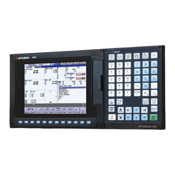
Mitsubishi Electric E70 Series Instruction Manual (782 pages)
Brand:
Mitsubishi Electric
| Category:
Control Systems
| Size: 7.85 MB
Table of Contents
Table of Contents
16
I Screen Operations
24
Operating the Setting and Display Unit
26
Display Unit and Keyboard Unit
27
Card Interface
30
Memory Card (Front IC Card) Interface
30
USB Memory
30
Caution
30
Screen Configuration
31
Operation Mode
32
MDI Status
32
Operation Status
32
Alarms/Warnings
33
Operation Messages
33
Screen Transition Diagram
34
Screen Selection Procedure
35
Setting Data
36
Setting Numerals and Alphabetic Characters
36
Inputting Operations
38
Operating the Screen
40
Changing the Menu
40
Types of Menus
40
Menu List
41
Displaying the Menu Function Outline
43
Directly Moving to the Menu Function
43
Guidance Function
44
Operation/Parameter Guidance
44
Alarm Guidance
49
Screen Saver (Backlight OFF) Function
52
Backlight off
52
Backlight on
53
Screen Capture
54
Menu Customization Function
55
Monitor Screens
58
Screen Configuration
60
Counter Display
64
Switching the Counter Types
65
Changing between <Auto/MDI> and <Manual
66
Operation Search
67
Executing an Operation Search
69
Changing Whether to Show or Hide the Comment Field
70
Changing the Sorting Method
71
Restart Search
72
Main Screen
75
Top Search Screen
77
File Setting Screen
78
MSTB History Screen
79
Operation Sequence for Program Restart
80
Executing Restart Search (Restart Type 1)
82
Executing Restart Search (Restart Type 2)
83
Changing the Device
84
Changing the Directory with the Main Screen
85
Returning to the Restart Position
85
Executing the MSTB Commands
88
Program Edit
89
Edit/Search Window
90
Trace
93
Displaying the Machine Position Trace
96
Canceling the Machine Position Trace
96
Changing the Display Range
97
Changing the Display Mode
99
Changing the Display Angle
100
Switching the Axis Movement Direction (+, -)
100
Switching the Full-Screen Display Mode
101
Precautions for Tracing
101
Program Check (2D)
102
Counter All-Axis Display
103
Tool Compensation Amount
105
Workpiece Coordinate System Compensation
109
Counter Setting
110
Origin Set, Origin Cancel
112
Manual Numerical Value Command
114
Modal Display
116
Program Tree Display
119
Integrated Time Display
120
Setting the Integrated Time
121
Setting the Time Display Selection
122
Common Variables
123
Setting Common Variables
125
Copying/Pasting Common Variables
125
Erasing Common Variables
126
Switching the Display Area
126
Local Variables
127
Displaying the Arbitrary Local Variables
129
Buffer Correction
130
PLC Switch Function
134
Turning PLC Switches ON/OFF
135
Load Meter Display
136
Spindle, Standby Display
137
All Spindles' Rotation Speed Display
138
Setup Screens
140
Screen Configuration
141
Tool Compensation Amount
143
Tool Compensation Amount (M System)
144
Setting the Tool Compensation Data
147
Switching the Input Method for the Tool Compensation Data
149
Erasing the Tool Compensation Data
150
Copying/Pasting the Tool Compensation Data
151
Disabling the Setting of Tool Compensation Amount
151
Tool Compensation Amount (L System)
152
Wear Data
152
Tool Length Data
155
Tool Nose Data
157
Operation Method
159
Disabling the Setting of Tool Compensation Amount
162
Tool Measurement
163
Tool Measurement (M System)
163
Tool Measurement (L System)
169
Tool Registration
192
Registering a Tool in the Magazine Pot
194
Setting the PLC Command
195
Setting/Erasing the Tool No. of Spindle/Standby Tools
195
Erasing the Tool Registration Data
196
Switching the Magazines to be Displayed
196
Tool Life Management
197
Displaying the Group List (M System: Tool Life Management I, II / L System: Tool Life Management II)
199
Displaying the Life Management Data in Group Units (M System)
203
Displaying the Life Management Data (L System: Tool Life Management I)
210
Displaying the Tool Life Management Data in Group Units (L System: Tool Life Management II)
212
Workpiece Coordinate System Offset
217
Setting the Coordinate System Offset Amount
219
Erasing the Coordinate System Offset Amount
219
Changing the Coordinate System Display
220
User Parameters
221
Setting the Parameters
223
Copying/Pasting Parameters
223
Parameter Configuration
225
Echoback
225
Ethernet Parameter Password
225
MDI Program Editing
226
Counter Setting
227
Manual Numerical Value Commands
228
T Code List
229
Edit Screens
232
Screen Configuration
233
Program Editing
234
Creating a New Machining Program
237
Editing a Machining Program
238
Editing MDI Program
240
Registering MDI Program in NC Memory
241
Erasing a File
242
Editing Operations
242
Changing the Display
243
Displaying an Arbitrary Line
244
Rewriting Data
245
Inserting Data
245
Deleting Data
246
Searching for Character Strings
248
Replacing Character Strings
250
Copying/Pasting Data
251
Adding Sequence No. (N No.) Automatically
252
G Code Guidance
255
Playback Editing (M System)
258
Program Check (2D)
262
Checking Continuously
266
Checking One Block at a Time
268
Canceling the Program Check
269
Setting the Coordinate System to Draw
269
Drawing During a Program Check
272
Changing the Display Range
272
Changing the Display Mode
274
Changing the Display Angle
275
Switching the Axis Movement Direction (+, -)
276
Switching to Full-Screen Display Mode
277
Setting Auto Graphic
278
Availability of Check Mode with Other Functions
281
Handling of Variable Commands, Programmable Parameter Input, and Programmable Compensation Data Input
282
Switching the Draw Path
283
Notes for Program Check (2D)
284
Program Input/Output
285
Changing the Valid Area
289
Selecting a Device, Directory, and File
290
Transferring a File
294
Comparing Files (Compare)
297
Erasing a File
298
Changing a File Name (Rename)
299
Creating a Directory
300
Merging a File
301
Formatting an External Device
302
List of File Names
302
Edit Lock B and C
303
Program Display Lock C
304
Data Protect Keys
305
The Batch Input/Output the Machining Program of NC Memory
306
Leading Zero
311
Diagnosis Screens
314
System Configuration Screen
315
Option Display Screen
318
I/F Diagnosis Screen
319
Displaying the PLC Device Data
322
Carrying out Modal Output
323
Carrying out One-Shot Output
324
Drive Monitor Screen
325
Servo Axis Unit Display Items
326
Spindle Unit Display Items
329
Display Items for the Power Supply Unit
332
Clearing the Alarm History
333
NC Memory Diagnosis Screen (NC Memory Diagn Screen)
334
Writing/Reading the Data Using the NC Data Designation
336
Alarm Screen
337
Alarm History
339
Self Diagnosis Screen
341
Data Sampling Screen
344
Sampling Parameter
346
Sampling Address
349
Executing NC Data Sampling
352
Outputting Sampling Data
353
Maintenance Screens
356
Parameter Screens
359
Changing the Parameter Display
364
Setting the Parameters
364
Copying/Pasting Parameters
366
User Parameters
367
Echo Back
368
Input/Output Screen
369
Changing the Valid Area
372
Selecting a Device, Directory and File
373
Transferring a File
380
Comparing Files (Compare)
383
Erasing a File
384
Changing a File Name (Rename)
384
Creating a Directory
385
Merging a File
386
Formatting an External Device
387
List of File Names
388
Edit Lock B and C
397
Data Protect Keys
398
Sharing Machining Data
400
The Batch Input/Output the Machining Program of NC Memory
402
All Backup Screen
407
Performing a Backup Operation
409
Performing a Restore Operation
409
System Setup Screen
410
Writing Initial Parameters
412
Adjust S-Analog Screen
413
Adjustment Preparations
414
Performing Automatic Adjustments
415
Performing Manual Adjustments
415
Selecting the Axis
419
Carrying out Dogless-Type Zero Point Initialization
420
Carrying out Dog-Type Zero Point Initialization
428
Precautions
428
Servo Diagnosis Screen
430
Diagnosis Data Collection Setting Screen
433
Performing a Data Collection Operation
435
Stopping a Data Collection Operation
435
Clearing a Collected Data
435
Machine Operations
436
Operation State
440
Operation State Correlation Diagram
441
Power off
441
Operations Not Ready
442
Operations Ready
442
Reset
442
Automatic Operation in Progress
442
Automatic Operation Pause
442
Automatic Operation Stop
443
Indicator Lamps
444
Control Unit Ready
445
In Automatic Operation
445
Automatic Operation Start Busy
445
Automatic Operation Pause Busy
445
Return to Reference Position
445
Alarm
445
M00
445
M02/M30
445
Reset Switch and Emergency Stop Button
446
Reset Switch
447
Emergency Stop Button
447
Operation Mode
448
Mode Selection Switch
449
Jog Feed Mode
449
Rapid Traverse Feed Mode
450
Manual Reference Position Return Mode
451
Outline
451
Detailed Description
451
Clear the Shift Amount for Coordinate System Setting When Manually Returning to the Reference Position
453
Incremental Feed Mode
454
Handle Feed Mode
454
Memory Mode
455
MDI Operation Mode
455
Operation Panel Switches in Operation Mode
456
Rapid Traverse Override
457
Cutting Feed Override
457
Spindle Override
457
Manual Feedrate
458
Handle/Incremental Feed Magnification
458
Handle Feed Axis Selection
458
Manual Pulse Generator
459
Cycle Start and Feed Hold
459
Feed Axis Selection
459
Operation Panel Switch Functions
460
Chamfering
461
Miscellaneous Function Lock
461
Single Block
461
Z Axis Cancel
461
Dry Run
461
Manual Override
461
Override Cancel
461
Optional Stop
462
Optional Block Skip
462
Manual Absolute
463
Mirror Image
464
Error Detect
465
Follow-Up Function
465
Axis Removal
465
F 1-Digit Feed
466
Outline
466
Detailed Description
466
Preautions
467
Manual/Automatic Synchronous Feed
468
Outline
468
Conditions for Validating Manual/Automatic Synchronous Feed
468
Operation During Manual/Automatic Simultaneous Operation
469
Operation When Automatic Operation Commands and Manual/Automatic Simultaneous Valid Selection Are Issued for same Axis
470
Other Precautions
472
Handle Interruption
473
Outline
473
Interruptible Conditions
473
Interruption Effective Axis
473
Axis Movement Speed Resulting from Interruption
474
Path Resulting after Handle Interruption
475
Handle Interruption in Tool Radius Compensation
477
Interrupt Amount Reset
479
Operation Procedure
479
All Axis Machine Lock
480
Each Axis Machine Lock
480
Deceleration Check
481
Functions
481
Deceleration Check Method
482
Deceleration Check When Opposite Direction Movement Is Reversed
484
Parameters
485
Precautions
486
External Deceleration
488
Outline
488
Function Description
488
Relation with Other Funcitons
489
Cautions / Restrictions
489
Reference Position Retract
490
Outline
490
Detailed Description
490
Spindle Orientation
491
Outline
491
Orientation Operation
492
Other Functions
496
Stored Stroke Limit
497
Stored Stroke Limit I
498
Stored Stroke Limit II
499
Stored Stroke Limit for Rotation Axis
500
Changing the Area for the Stored Stroke Limit I
500
Precautions
500
Chuck Barrier/Tailstock Barrier (L System)
501
Detailed Description
501
Restrictions
504
Manual Synchronous Tapping
505
Outline
505
Command Format
505
Operation Procedures
505
Precautions
505
System Lock
506
Detailed Description
506
Caution
508
Maintenance
512
Daily Maintenance and Periodic Inspection and Maintenance
512
Maintenance Items
513
Escutcheon
513
LCD Panel
513
Compact Flash/Usb Memory
514
Hardware Replacement Methods
516
Durable Parts
517
Control Unit Battery
517
Backlight
519
Fuse
521
Control Unit Protection Fuse
521
Operation Panel I/O Unit Protection Fuse
521
Key Sheet
522
Control Unit
523
Installation on FCU7-DU120-13 (8.4-Type)
525
Display Unit
526
Keyboard Unit
527
Operation Panel I/O Unit
528
Compactflash (CF) Card
529
USB Memory
530
Appendixes
534
Appendix 1 List of Function Codes
535
Appendix 2 Table of Command Value Ranges
537
Appendix 3 Circular Cutting Radius Error
545
Appendix 4 Registering/Editing the Fixed Cycle Program
547
Appendix 4.1 Fixed Cycle Operation Parameters
547
Appendix 4.2 Transmitting/Erasing the Fixed Cycle Program
547
Appendix 4.3 Standard Fixed Cycle Subprogram (for L System)
548
Appendix 4.4 Standard Fixed Cycle Subprogram (for M System)
555
Appendix 5 RS-232C I/O Device Parameter Setting Examples
562
Appendix 6 Explanation of Alarms
565
Appendix 6.1 Operation Errors (M)
565
Appendix 6.2 Stop Codes (T)
586
Appendix 6.3 Servo/Spindle Alarms (S)
593
Appendix 6.3.1 Servo Errors (S01/S03/S04)
593
Appendix 6.3.2 Initial Parameter Errors (S02)
608
Appendix 6.3.3 Safety Function Errors (S05)
608
Appendix 6.3.4 Parameter Errors (S51)
609
Appendix 6.3.5 Servo Warnings (S52)
610
Appendix 6.3.6 Safety Function Warnings (S53)
612
Appendix 6.4 MCP Alarms (Y)
613
Appendix 6.5 System Alarms (Z)
625
Appendix 6.6 Absolute Position Detection System Alarms (Z7*)
633
Appendix 6.7 Distance-Coded Reference Scale Errors (Z8*)
636
Appendix 6.8 Emergency Stop Alarms (EMG)
637
Appendix 6.9 Computer Link Errors (L)
640
Appendix 6.10 User PLC Alarms (U)
641
Appendix 6.11 Network Service Errors (N)
644
Appendix 6.12 Program Errors (P)
646
Appendix 7 Operation Messages
679
Appendix 7.1 Search-Related Operation Messages
679
Appendix 7.2 Graphic Display-Related Operation Messages
680
Appendix 7.3 Variable (Common Variables, Local Variables) - Related Operation Messages
681
Appendix 7.4 PLC Switch-Related Operation Messages
681
Appendix 7.5 Compensation-Related (Tool Compensation, Coordinate System Offset) Operation Messages
681
Appendix 7.6 Data Input/Output-Related Operation Messages
682
Appendix 7.7 Parameter-Related Operation Messages
685
Appendix 7.8 Measurement-Related Operation Messages
686
Appendix 7.9 Tool (Tool Registration, Tool Life) -Related Operation Messages
688
Appendix 7.10 Editing-Related Operation Messages
689
Appendix 7.11 Diagnosis-Related Operation Messages
691
Appendix 7.12 Maintenance-Related Operation Messages
692
Appendix 7.13 Data Sampling-Related Operation Messages
694
Appendix 7.14 Absolute Position Detection-Related Operation Messages
694
Appendix 7.15 System Setup-Related Operation Messages
695
Appendix 7.16 Automatic Backup-Related Operation Messages
695
Appendix 7.17 Alarm History-Related Operation Messages
696
Appendix 7.18 Devicenet-Related Operation Messages
697
Appendix 7.19 Other Operation Messages
698
Appendix 8 User Parameters
701
Advertisement
Mitsubishi Electric E70 Series Connection Manual (216 pages)
Brand:
Mitsubishi Electric
| Category:
Control Systems
| Size: 9.07 MB
Table of Contents
Table of Contents
22
System Configuration
26
System Basic Configuration Drawing
27
General Connection Diagram
28
List of Configuration
30
List of Units
30
Durable Parts
31
Replacements
31
List of Cables
32
General Specifications
34
Environment Conditions
35
Control Unit
36
Display Unit
46
Keyboard Unit
47
Operation Panel I/O Unit
49
Remote I/O Unit
61
External Power Supply Unit
68
Manual Pulse Generator
70
Synchronous Feed Encoder
72
MITSUBISHI CNC Machine Operation Panel
73
MITSUBISHI CNC Machine Operation Panel a
73
MITSUBISHI CNC Machine Operation Panel B
80
Exclusive CF Cards for MITSUBISHI CNC
84
Precautions for Use of Commercially Available CF Cards
84
Installation
86
Heat Radiation Countermeasures
87
Noise Countermeasures
90
Connection of FG (Frame Ground)
90
Shield Clamping of Cables
91
Connecting Spark Killers
91
Unit Installation
92
Display Unit
92
Keyboard Unit
93
Operation Panel I/O Unit
93
Control Unit Battery
94
Connection
96
Precautions for Wiring
97
Precautions When Connecting/Disconnecting Cables
97
Precautions for Using Optical Communication Cable
100
Optical Communication Cable Outline and Parts
100
Precautions for Handling Optical Communication Cable
100
Precautions for Laying Optical Communication Cable
101
Precautions for Connecting 24V Power Supply
101
Connection of Control Unit
102
Control Unit Connection System Drawing
102
Connecting with Power Supply
103
Connecting with Emergency Stop Signal
104
Connecting with Operation Panel I/O Unit
106
Connecting with Drive Unit
107
Connecting with MDS-DM2 Series
108
Connecting with MDS-DJ Series
109
Connecting with I/O Devices Via CC-Link
110
Connecting with RS-232C Device
112
Connecting with Skip Signal (Sensor)
114
Connecting with Synchronous Feed Encoder/ Manual Pulse Generator
116
Handle Numbers
116
Connecting with Safety Observing I/O Device
117
Connection of Operation Panel I/O Unit
118
Operation Panel I/O Unit Connection System Drawing
118
Connecting with Keyboard Unit
119
Connecting with Manual Pulse Generator (MPG)
120
Handle Numbers
121
Connecting with Machine Operation Panel
121
Wiring for 24V Common Input
122
Wiring for 0V Common Input
122
Wiring for Source Type Output (FCU7-DX621/DX711/DX721/DX731)
123
Outline of Analog Signal Output Circuit
124
Connection of Remote I/O Unit
125
Connection and Station No. Setting on Remote I/O Unit
125
Station No. Setting When Using Multiple Remote I/O Units
127
Connecting FCUA-DX101/141 Unit with Machine Control Signal
131
Connecting FCUA-DX141 Unit with Analog Input/Output Signal
133
Connecting FCUA-DX111 Unit with Machine Control Signal
134
Connecting FCUA-DX121 Unit with Machine Control Signal
136
Connection of MITSUBISHI CNC Machine Operation Panel
138
Appendix 1 Cable
142
Appendix 1.1 Cable Wire and Assembly
144
Appendix 1.2 CNP2E-1 Cable
146
Appendix 1.3 CNP3EZ-2P/CNP3EZ-3P Cable
147
Appendix 1.4 CNV22J-K1P / CNV22J-K2P Cable
148
Appendix 1.5 CNV2E-8P/CNV2E-9P Cable
149
Appendix 1.6 CNV2E-HP Cable
150
Appendix 1.7 CNV2E-K1P / CNV2E-K2P Cable
151
Appendix 1.8 DG21 Cable
152
Appendix 1.9 DG22 Cable
153
Appendix 1.10 DG23 Cable
154
Appendix 1.11 DG24 Cable
155
Appendix 1.12 DG25 Cable
156
Appendix 1.13 F023/F024 Cable
157
Appendix 1.14 F034/F035 Cable
158
Appendix 1.15 F070 Cable
159
Appendix 1.16 F110 Cable
160
Appendix 1.17 F120 Cable
161
Appendix 1.18 F170 Cable
162
Appendix 1.19 F221 Cable
163
Appendix 1.20 F320/F321 Cable
164
Appendix 1.21 F351 Cable
165
Appendix 1.22 FCUA-R030 Cable
166
Appendix 1.23 FCUA-R031 Cable
167
Appendix 1.24 FCUA-R050/R054 Cable
168
Appendix 1.25 FCUA-R211 Cable
169
Appendix 1.26 FCUA-R300/FCUA-R301 Cable
170
Appendix 1.27 G011 Cable
172
Appendix 1.28 G023/G024 Cable
173
Appendix 1.29 G071 Cable
174
Appendix 1.30 G300 Cable
175
Appendix 1.31 G301 Cable
176
Appendix 1.32 G380 Cable
177
Appendix 1.33 G395 Cable
178
Appendix 1.34 G396 Cable
179
Appendix 1.35 G460 Cable
180
Appendix 1.36 MR-BKS1CBL-A1-H / MR-BKS1CBL-A2-H Cable
181
Appendix 1.37 MR-PWS1CBL-A1-H / MR-PWS1CBL-A2-H Cable
182
Appendix 1.38 R-TM Terminator Connector
183
Appendix 1.39 SH21 Cable
184
Appendix 1.40 SH41 Cable
185
Appendix 1.41 List of Cable Connector Sets
186
Appendix 2 EMC Installation Guidelines
188
Appendix 2.1 Introduction
189
Appendix 2.2 EMC Directives
189
Appendix 2.3 EMC Measures
190
Appendix 2.4 Panel Structure
190
Appendix 2.4.1 Measures for Control Panel Body
190
Appendix 2.4.2 Measures for Door
191
Appendix 2.4.3 Measures for Power Supply
191
Appendix 2.5 Measures for Wiring in Panel
192
Appendix 2.5.1 Precautions for Wiring in Panel
192
Appendix 2.5.2 Shield Treatment of Cables
193
Appendix 2.6 EMC Countermeasure Parts
195
Appendix 2.6.1 Shield Clamp Fitting
195
Appendix 2.6.2 Ferrite Core
196
Appendix 2.6.3 Surge Absorber
197
Appendix 2.6.4 Selection of Stabilized Power Supply
199
Appendix 3 Restrictions for Lithium Batteries
200
Appendix 3.1 Restriction for Packing
201
Appendix 3.1.1 Target Products
202
Appendix 3.1.2 Handling by User
203
Appendix 3.1.3 Reference
204
Appendix 3.2 Products Information Data Sheet (er Battery)
205
Appendix 3.3 Issuing Domestic Law of the United States for Primary Lithium Battery Transportation
207
Appendix 3.3.1 Outline of Regulation
207
Appendix 3.3.2 Target Products
207
Appendix 3.3.3 Handling by User
207
Appendix 3.3.4 Reference
207
Appendix 3.4 Restriction Related to EU Battery Directive
208
Appendix 3.4.1 Important Notes
208
Appendix 3.4.2 Information for End-User
208
Appendix 4 Precautions for Compliance to Ul/C-UL Standards
210
Advertisement
Related Products
Mitsubishi Electric E80 TypeA
Mitsubishi Electric E80 TypeB
Mitsubishi Electric Evolution+ s-MEXT
Mitsubishi Electric ecodan EHST20D-MEC
Mitsubishi Electric EF-50UFT-GL
Mitsubishi Electric ecodan EHST30C-MED
Mitsubishi Electric ecodan EHPT20X-MHEDW
Mitsubishi Electric ERPX-YM9D
Mitsubishi Electric ERST30D-YM9ED
Mitsubishi Electric EHPT20X-TM9D.UK
Mitsubishi Electric Categories
Air Conditioner
Controller
Projector
Inverter
Heat Pump
More Mitsubishi Electric Manuals
Login
Sign In
OR
Sign in with Facebook
Sign in with Google
Upload manual
Upload from disk
Upload from URL