Vega WEIGHTRAC 31 Operating Instructions Manual
Radiation-based sensor for mass flow detection
Hide thumbs
Also See for WEIGHTRAC 31:
- Operating instructions manual (88 pages) ,
- Operating instructions manual (84 pages)

Related Manuals for Vega WEIGHTRAC 31


Summary of Contents for Vega WEIGHTRAC 31
- Page 1 Operating Instructions Radiation-based sensor for mass flow detection WEIGHTRAC 31 4 … 20 mA/HART - four-wire Document ID: 42374...
-
Page 2: Table Of Contents
Status messages ......................55 Rectify faults ........................59 Exchanging the electronics module ................60 Software update ......................61 How to proceed in case of repair ..................61 Dismounting Dismounting steps......................63 WEIGHTRAC 31 • 4 … 20 mA/HART - four-wire... - Page 3 10.2 Dimensions ........................69 Safety instructions for Ex areas Please note the Ex-specific safety information for installation and op- eration in Ex areas. These safety instructions are part of the operating instructions manual and come with the Ex-approved instruments. Editing status: 2013-11-11 WEIGHTRAC 31 • 4 … 20 mA/HART - four-wire...
-
Page 4: About This Document
This arrow indicates a single action. Sequence of actions Numbers set in front indicate successive steps in a procedure. Battery disposal This symbol indicates special information about the disposal of bat- teries and accumulators. WEIGHTRAC 31 • 4 … 20 mA/HART - four-wire... -
Page 5: For Your Safety
This measuring system uses gamma rays. Therefore take note of the instructions for radiation protection in chapter "Product description". Any work on the source container may only be carried out under the supervision of a qualified radiation protection officer. WEIGHTRAC 31 • 4 … 20 mA/HART - four-wire... -
Page 6: Ce Conformity
That is why we have introduced an environment management system with the goal of continuously improving company environmental pro- tection. The environment management system is certified according to DIN EN ISO 14001. Please help us fulfill this obligation by observing the environmental instructions in this manual: • Chapter "Packaging, transport and storage" • Chapter "Disposal" WEIGHTRAC 31 • 4 … 20 mA/HART - four-wire... -
Page 7: Product Description
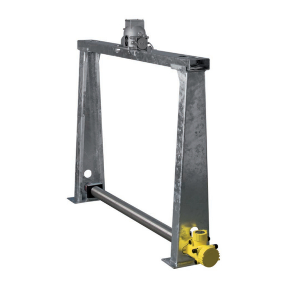
Go to www.vega.com, "VEGA Tools" and "Serial number search". As an alternative, you can find the data via your Smartphone: • Download the smartphone app "VEGA Tools" from the "Apple App Store" or the "Google Play Store" • Scan the Data Matrix code on the type label of the instrument or •... - Page 8 – Ex-specific "Safety instructions" (with Ex versions) – if necessary, further certificates Fig. 2: WEIGHTRAC 31 Source container (e.g. SHLD-1) WEIGHTRAC 31 Support stand Crossbeam Clamp collars Note: The appropriate source container (e.g. SHLD-1) must be ordered separately. WEIGHTRAC 31 • 4 … 20 mA/HART - four-wire...
-
Page 9: Principle Of Operation
• Avoiding mechanical shock and vibration • Storage and transport Storage and transport temperature see chapter "Supplement - temperature Technical data - Ambient conditions" • Relative humidity 20 … 85 % WEIGHTRAC 31 • 4 … 20 mA/HART - four-wire... -
Page 10: Accessories And Replacement Parts
WEIGHTRAC 31. The electronics module can only be exchanged by VEGA service technician. Basic mounting set If you have ordered WEIGHTRAC 31 without a measuring frame, a basic mounting set is enclosed with the instrument. It includes every- thing needed to fasten the measuring tube reliably. Measuring frame for... - Page 11 (in Ger- many, for example, the radiation protection ordinance). We are at your disposal for further information concerning radiation protection and regulations in other countries. WEIGHTRAC 31 • 4 … 20 mA/HART - four-wire...
-
Page 12: Mounting
Prior to setup you have to replace these protective caps with ap- proved cable glands or close the openings with suitable blind plugs. The suitable cable glands and blind plugs come with the instrument. WEIGHTRAC 31 • 4 … 20 mA/HART - four-wire... -
Page 13: Mounting Instructions
You can position and mount WEIGHTRAC 31 in the measuring frame from both sides. Direct the exit angle of the source container to the WEIGHTRAC 31. Mount the source container at the specified distance to the conveyor belt. Secure the area with a safety fence and protective grating so that no one can reach into the dangerous area. - Page 14 6. Insert the screws (1), each with one wedge lock washer (2), through the clamp collars (4). 7. Place a wedge lock washer (2) from below on each screw (1) and screw one nut (7) onto each screw. WEIGHTRAC 31 • 4 … 20 mA/HART - four-wire...
- Page 15 Avoid places where the product accumulates or falls back over the worm shaft. - Chain conveyors When mounting the WEIGHTRAC 31 on a chain conveyor, the instal- lation angle is very important for optimal irradiation. Follow the instructions in the "Source Sizing" document.
- Page 16 (6). Mount the measuring frame as well centered as possible and at an angle of 90° above the conveyor belt. Keep enough lateral distance to the conveyor belt. WEIGHTRAC 31 • 4 … 20 mA/HART - four-wire...
- Page 17 120 mm (4.72") 15 mm (0.59") 150 mm (5.91") Fig. 6: Drilling plan for support stands 3. Use suitable washers (15) for mounting the support stands (6). WEIGHTRAC 31 • 4 … 20 mA/HART - four-wire...
- Page 18 4. Tighten the screws (14) evenly with 45 Nm (33.2 lb ft). Mounting - Sensor 1. Place two of the clamp collars (11) on the fastening brackets of the support stands (6). WEIGHTRAC 31 • 4 … 20 mA/HART - four-wire...
- Page 19 3. Place the other two clamp collars (11) according to the illustration above the clamp collars that are already in place (11). 4. Place a metallic cover plate (10) according to the illustration on each upper clamp collar (11). WEIGHTRAC 31 • 4 … 20 mA/HART - four-wire...
- Page 20 4. Place a wedge lock washer (2) from below on each screw (1) and screw one nut (5) onto each screw. 5. Align the source container (7) and tighten the nuts (5) evenly with 45 Nm (33.2 lb ft). WEIGHTRAC 31 • 4 … 20 mA/HART - four-wire...
- Page 21 If you want to carry out such measures later on, contact our specialists to ensure that the accuracy of the application is not impaired. If these measures are not sufficient to maintain the max. ambient temperature, you could consider using the water cooling system we offer for WEIGHTRAC 31. WEIGHTRAC 31 • 4 … 20 mA/HART - four-wire...
- Page 22 4 Mounting The water cooling must also be included in the calculations for the measuring point. Contact our specialists regarding the dimensioning of the water cooling. WEIGHTRAC 31 • 4 … 20 mA/HART - four-wire...
-
Page 23: Connecting To Power Supply
In the sensor, the screen must be connected directly to the internal ground terminal. The ground terminal on the outside of the housing must be connected to the potential equalisa- tion (low impedance). WEIGHTRAC 31 • 4 … 20 mA/HART - four-wire... - Page 24 3. Remove approx. 10 cm (4 in) of the cable mantle, strip approx. 1 cm (0.4 in) of insulation from the ends of the individual wires 4. Insert the cable into the sensor through the cable entry WEIGHTRAC 31 • 4 … 20 mA/HART - four-wire...
- Page 25 9. Tighten the compression nut of the cable entry gland. The seal ring must completely encircle the cable 10. Screw the housing cover back on The electrical connection is finished. WEIGHTRAC 31 • 4 … 20 mA/HART - four-wire...
-
Page 26: 5.2 Connection - Mass Flow Detection
Signal input 4 … 20 mA Switching input for NPN transistor 7 Switching input floating Transistor output Interface for sensor-sensor communication (MGC) 10 Setting the bus address for sensor-sensor communication (MGC) MGC = Multi Gauge Communication WEIGHTRAC 31 • 4 … 20 mA/HART - four-wire... - Page 27 Signal input 4 … 20 mA Switching input for NPN transistor 5 Switching input floating Transistor output Interface for sensor-sensor communication (MGC) Setting the bus address for sensor-sensor communication (MGC) MGC = Multi Gauge Communication WEIGHTRAC 31 • 4 … 20 mA/HART - four-wire...
-
Page 28: Connection - Summation
The address setting (MGC) on the Slave instruments can be freely selected. Only the address "0 - 0" is reserved for the Master instru- ment. Connect the instruments according to the following wiring plan: WEIGHTRAC 31 • 4 … 20 mA/HART - four-wire... - Page 29 S Slave instrument Information: For example, a radial connection would be also possible as an alter- native. Take note of the polarity. The selection of the two terminal pairs is individual. WEIGHTRAC 31 • 4 … 20 mA/HART - four-wire...
-
Page 30: Connection - Tachometer
If the belt stops, measurement is also halted for this period. Without a belt stop signal, WEIGHTRAC 31 would continue summing the delivery rate. You can implement the belt stop signal with a switching relay or a signal from the plant control system (PLC). - Page 31 Fig. 17: Belt speed - plant control system (PLC) or tachometer (analogue) A Output Plant control system (PLC) Tachometer (analogue) Diode (blocking voltage > 50 V) Tachometer (digital) Fig. 18: Digital tachometer (TACHO.A1A4M) Not required with output "open collector" WEIGHTRAC 31 • 4 … 20 mA/HART - four-wire...
- Page 32 5 Connecting to power supply The digital tachometer is powered by WEIGHTRAC 31. When using the digital tachometer, you must power WEIGHTRAC 31 with max. 24 V. The following cable colors are valid if the tachometer is ordered with cable. Fig. 19: Belt speed - plant control system (PLC) or tachometer (analogue)
-
Page 33: Adjustment With The Display And Adjustment Module
The display and adjustment module is powered by the sensor, an ad- ditional connection is not necessary. Fig. 20: Insert display and adjustment module Note: If you intend to retrofit the instrument with a display and adjustment module for continuous measured value indication, a higher cover with an inspection glass is required. WEIGHTRAC 31 • 4 … 20 mA/HART - four-wire... -
Page 34: Adjustment System
60 minutes after the last pressing of a key, an automatic reset to measured value indication is triggered. Any values not confirmed with [OK] will not be saved. Display and adjustment module - Indication of system parameters Note: Instrument start During the first setup or after an instrument reset the instrument starts with an error message (F025 - Invalid linearization table). This is quite mormal because the sensor doesn't yet have any reference points WEIGHTRAC 31 • 4 … 20 mA/HART - four-wire... - Page 35 Push the button "OK" to acknowledge the error message. Carry out the adjustment with PACTware. With the display and adjustment module you can only read out the pa- rameters of the WEIGHTRAC 31. Carry out the parameter adjustment of the instrument with the adjustment software PACTware. You can find the parameter adjustment in the next chapter.
- Page 36 Instrument version - shows hardware and software version of the instrument • Date of manufacture - shows calibration date and the date of the last change • Instrument features - shows further instrument features WEIGHTRAC 31 • 4 … 20 mA/HART - four-wire...
-
Page 37: Saving The Parameter Adjustment Data
If it is necessary to exchange a sensor, the display and adjustment module is inserted into the replacement instrument and the data are likewise written into the sensor via the menu item "Copy sensor data". WEIGHTRAC 31 • 4 … 20 mA/HART - four-wire... -
Page 38: Setup With Pactware
Connection via HART Fig. 23: Connecting the PC via HART to the signal cable WEIGHTRAC 31 2 HART resistance 250 Ω (optional depending on processing) Connection cable with 2 mm pins and terminals Processing system/PLC/Voltage supply Voltage supply Necessary components: WEIGHTRAC 31 • 4 … 20 mA/HART - four-wire... -
Page 39: Parameter Adjustment With Pactware
The parameter adjustment adapts the instrument to the application conditions. Note: Instrument start During the first setup or after an instrument reset the instrument starts with an error message (F025 - Invalid linearization table). This is quite mormal because the sensor doesn't yet have any reference points for correct operation. Push the button "OK" to acknowledge the error message. WEIGHTRAC 31 • 4 … 20 mA/HART - four-wire... - Page 40 The normal reduction of the emitter activity is hence considered through the radioactive decay. The WEIGHTRAC 31 requires this information of the automatic decay compensation. This ensures an interference-free measurement over the complete life time of the gamma emitter - an annual recalibration is not necessary.
- Page 41 Information: If you want to operate your instrument as master of a mass flow sum- mation, select application "Mass flow (belt/spiral)". In this window you can carry out the settings for the speed of the Process speed (step 2) conveyor belt or the spiral conveyor. WEIGHTRAC 31 • 4 … 20 mA/HART - four-wire...
- Page 42 Here you can enter the min. and max. speed of the conveyor belt. Select inputs (step 3) In this window you can carry out the settings for the inputs of WEIGHTRAC 31. WEIGHTRAC 31 • 4 … 20 mA/HART - four-wire...
- Page 43 In the case of modulated measuring current (dithering), the last valid current value is maintained and the current output modulates a square-wave voltage ±1 mA around this value. Information: If you have activated the X-ray alarm, you have to enter in the next step the type and the data of the connected X-ray alarm sensor. WEIGHTRAC 31 • 4 … 20 mA/HART - four-wire...
- Page 44 With this menu item the natural background radiation can be faded out. For this purpose, the WEIGHTRAC 31 measures the natural back- ground radiation and sets the pulse rate to zero. In the future, the pulse rate from this background radiation will be automatically deducted from the total pulse rate. This means: only the component of the pulse rate originating from the source will be displayed.
- Page 45 "t/h". This corresponds to an output current of 20 mA. Enter in the menu window "Min. process value" the min. level (empty), for example in "t/h". This corresponds to an output current of 4 mA. WEIGHTRAC 31 • 4 … 20 mA/HART - four-wire...
- Page 46 With the setting "Automatic", the instrument itself calculates a suitable damping on the basis of the adjustment and the measured value changes. This setting is particularly suitable for application where fast and slow level changes occur. WEIGHTRAC 31 • 4 … 20 mA/HART - four-wire...
- Page 47 Fig. 31: Select behaviour of the current outputs In this menu item you can define the characteristics of the sensor and its behaviour in case of a fault. In this menu item you can define the behaviour of the current output. You can determine the current with min. and max. level separately. Setup/Relay (step 9) Fig. 32: Relay output WEIGHTRAC 31 • 4 … 20 mA/HART - four-wire...
- Page 48 You can set material quantity that causes a counting pulse to be outputted via the digital output (NPN transistor). The leak volume suppression determines which degree of filling (in percent) activates the totalizer. With this you can avoid a continued summation of contamination or slight buildup on an otherwise empty conveyor belt. WEIGHTRAC 31 • 4 … 20 mA/HART - four-wire...
- Page 49 3. Click the button "Determine zero rate" 4. Let the conveyor belt run for two to three belt lengths 5. Terminate the zero rate determination 6. Stop conveyor belt The determined value of the zero rate is transferred to the sensor Note: In case of heavy belt wear, this zero rate determination should be car- ried out regularly to keep the accuracy constant. WEIGHTRAC 31 • 4 … 20 mA/HART - four-wire...
- Page 50 Another possibility would be to transfer the conveyed material to a container sitting on load cells. You can carry out the linearization with two different principles: • Dynamically - with running conveyor belt • Statically - with stationary conveyor belt WEIGHTRAC 31 • 4 … 20 mA/HART - four-wire...
- Page 51 This assigns a corresponding material quantity to the current pulse rate. 8. Click to "Complete". Accept the value pair with "Accept". Carry out such a linearization with several different loading heights. We recommend two to three measurements. The measurement will be more reliable if you enter several lineariza- tion points with different loading heights. WEIGHTRAC 31 • 4 … 20 mA/HART - four-wire...
- Page 52 Accept the value pair with "Accept". 11. Repeat this procedure with a larger quantity of material (e.g. 120 kg) until you have reached the max. loading height of the conveyor belt. WEIGHTRAC 31 • 4 … 20 mA/HART - four-wire...
- Page 53 4 … 20 mA, < 3.6 mA mode Current output Min. current 3.8 mA, max. current Min./Max. 20.5 mA X-ray alarm Modulated measuring current Reference value None - Relay Block adjustment Released WEIGHTRAC 31 • 4 … 20 mA/HART - four-wire...
-
Page 54: Saving The Parameter Adjustment Data
Standard Address 0 Saving the parameter adjustment data We recommend documenting or saving the parameter adjustment data via PACTware. That way the data are available for multiple use or service purposes. WEIGHTRAC 31 • 4 … 20 mA/HART - four-wire... -
Page 55: Diagnostics And Service
PACTware/DTM or EDD. Out of specification: The measured value is unstable because the instrument specification is exceeded (e.g. electronics temperature). This status message is inactive by default. It can be activated by the user via PACTware/DTM or EDD. WEIGHTRAC 31 • 4 … 20 mA/HART - four-wire... - Page 56 – Restart instrument – Exchanging the electronics EPROM hard- ware error F035 – Error in the internal instru- – Carry out a reset ment communication – Exchanging the electronics EPROM data error WEIGHTRAC 31 • 4 … 20 mA/HART - four-wire...
- Page 57 F080 – Instrument error – Restart instrument – Call our service System error F086 – Error in the Fieldbus com- – Restart instrument munication – Call our service Communica- tion error WEIGHTRAC 31 • 4 … 20 mA/HART - four-wire...
- Page 58 – Wait for the automatic end Simulation after 60 mins. Out of specification The following table shows the error codes and text messages in the status message "Out of specification" and provides information on causes as well as corrective measures. WEIGHTRAC 31 • 4 … 20 mA/HART - four-wire...
-
Page 59: Rectify Faults
The following table describes possible errors in the tion) current signal and helps to remove them: Error Cause Rectification 4 … 20 mA signal Loading fluctua- Adjust damping via PACTware/DTM not stable tions Conveyor belt was Carry out a zero rate determination changed WEIGHTRAC 31 • 4 … 20 mA/HART - four-wire... -
Page 60: Exchanging The Electronics Module
Exchanging the electronics module If the electronics module is defective, it can be replaced by the user. In Ex applications, only instruments and electronics modules with ap- propriate Ex approval may be used. WEIGHTRAC 31 • 4 … 20 mA/HART - four-wire... -
Page 61: Software Update
By doing this you help us carry out the repair quickly and without hav- ing to call back for needed information. If a repair is necessary, please proceed as follows: • Print and fill out one form per instrument • Clean the instrument and pack it damage-proof WEIGHTRAC 31 • 4 … 20 mA/HART - four-wire... - Page 62 Attach the completed form and, if need be, also a safety data sheet outside on the packaging • Please contact the agency serving you to get the address for the return shipment. You can find the agency on our home page www.vega.com. WEIGHTRAC 31 • 4 … 20 mA/HART - four-wire...
-
Page 63: Dismounting
Pass the instrument directly on to a spe- cialised recycling company and do not use the municipal collecting points. These may be used only for privately used products according to the WEEE directive. WEIGHTRAC 31 • 4 … 20 mA/HART - four-wire... - Page 64 In case the radiation intensity decreases, for example due to rising loading volume of the conveyor belt, the measured value of WEIGHTRAC 31 changes in proportion to the loading volume. WEIGHTRAC 31 • 4 … 20 mA/HART - four-wire...
- Page 65 1829 mm (72 in) (77.17 in) (68.23 in) (61.02 in) (58.46 in) Measuring width (L) 610 … 1829 mm (24 … 72 in) Analogue input Ʋ Input type 4 … 20 mA, passive WEIGHTRAC 31 • 4 … 20 mA/HART - four-wire...
- Page 66 The contact is then no longer suitable for switching low-level signal circuits. Contact material (relay contacts) AgNi or AgSnO and Au plated WEIGHTRAC 31 • 4 … 20 mA/HART - four-wire...
- Page 67 Time span after a sudden measuring distance change by max. 0.5 m in liquid applications, max 2 m with bulk solids applications, until the output signal has taken for the first time 90 % of the final value (IEC 61298-2). Tested according to the guidelines of German Lloyd, GL directive 2. WEIGHTRAC 31 • 4 … 20 mA/HART - four-wire...
- Page 68 Time zone Ex factory Rate deviation max. 10.5 min/year Measurement electronics temerature Resolution 1 °C (1.8 °F) Accuracy ±1 °C (1.8 °F) Voltage supply Operating voltage 20 … 72 V DC or 20 … 253 V AC, 50/60 Hz Interpolation protection Available Max. power consumption 6 VA (AC); 4 W (DC) WEIGHTRAC 31 • 4 … 20 mA/HART - four-wire...
- Page 69 Approvals Instruments with approvals can have different technical data depending on the version. For that reason the associated approval documents of these instruments must be carefully noted. They are part of the delivery or can be downloaded under www.vega.com and "VEGA Tools" as well as under "Downloads" and "Approvals". 10.2 Dimensions The following dimensional drawings represent only an extract of all possible versions.
- Page 70 ½ NPT (4.69") 169 mm (6.65") 116,5 mm 175 mm (4.59") (6.89") 90 mm 100 mm (3.54") (3.94") 143,5 mm (5.65") Fig. 38: Aluminium housing or stainless steel housing - Precision casting WEIGHTRAC 31 • 4 … 20 mA/HART - four-wire...
- Page 71 10 Supplement WEIGHTRAC 31 ø 76,2 mm (3") Fig. 39: WEIGHTRAC 31 Measurement width WEIGHTRAC 31 • 4 … 20 mA/HART - four-wire...
- Page 72 70 mm 70 mm (2.76") (2.76") Fig. 40: WEIGHTRAC 31 in the measuring frame with source container SHLD-1 (can be ordered separately) Maximum conveyor belt width Total width - Crossbeam Clear width (internal dimension) - measuring frame Total height - measuring frame...
- Page 73 (102.32 in) (92.8 in) (90.24 in) (107.99 in) 2800 mm 3198 mm 2971 mm 2775 mm 2710 mm 3000 mm (110.24 in) (125.91 in) (116.97 in) (109.25 in) (106.69 in) (118.11 in) WEIGHTRAC 31 • 4 … 20 mA/HART - four-wire...
- Page 74 Les lignes de produits VEGA sont globalement protégées par des droits de propriété intellec- tuelle. Pour plus d'informations, on pourra se référer au site www.vega.com. VEGA lineas de productos están protegidas por los derechos en el campo de la propiedad indus- trial. Para mayor información revise la pagina web www.vega.com.
- Page 75 Handling permit 11 Status messages 55 Heat 21 Summation 43 Input 42 Tachometer 10 Installation position 13 Tachometer Belt speed Speed 30 Instrument features 36 Totalizer 48 Instrument version 36 Type label 7 Isotope WEIGHTRAC 31 • 4 … 20 mA/HART - four-wire...
- Page 76 INDEX Unit - Belt speed 42 Voltage supply 23, 68 Water cooling 21 X-ray alarm 43 WEIGHTRAC 31 • 4 … 20 mA/HART - four-wire...
- Page 77 Notes WEIGHTRAC 31 • 4 … 20 mA/HART - four-wire...
- Page 78 Notes WEIGHTRAC 31 • 4 … 20 mA/HART - four-wire...
- Page 79 Notes WEIGHTRAC 31 • 4 … 20 mA/HART - four-wire...
- Page 80 Subject to change without prior notice © VEGA Grieshaber KG, Schiltach/Germany 2013 VEGA Grieshaber KG Phone +49 7836 50-0 Am Hohenstein 113...
Need help?
Do you have a question about the WEIGHTRAC 31 and is the answer not in the manual?
Questions and answers