Vega WEIGHTRAC 31 Operating Instructions Manual
Radiometric sensor for mass flow detection
Hide thumbs
Also See for WEIGHTRAC 31:
- Operating instructions manual (88 pages) ,
- Operating instructions manual (80 pages)

Related Manuals for Vega WEIGHTRAC 31


Summary of Contents for Vega WEIGHTRAC 31
- Page 1 Operating Instructions Radiometric sensor for mass flow detection WEIGHTRAC 31 Four-wire 4 … 20 mA/HART Document ID: 42374...
-
Page 2: Table Of Contents
Diagnostics and servicing ....................60 Maintenance ........................60 Status messages ......................60 Rectify faults ........................63 Exchanging the electronics module ................64 Software update ......................65 How to proceed if a repair is necessary ................65 WEIGHTRAC 31 • Four-wire 4 … 20 mA/HART... - Page 3 10.4 Trademark ........................78 Safety instructions for Ex areas Take note of the Ex specific safety instructions for Ex applications. These instructions are attached as documents to each instrument with Ex approval and are part of the operating instructions. Editing status: 2021-11-25 WEIGHTRAC 31 • Four-wire 4 … 20 mA/HART...
-
Page 4: About This Document
Symbols used Document ID This symbol on the front page of this instruction refers to the Docu- ment ID. By entering the Document ID on www.vega.com you will reach the document download. Information, note, tip: This symbol indicates helpful additional infor- mation and tips for successful work. -
Page 5: For Your Safety
This measuring system uses gamma rays. Therefore take note of the instructions for radiation protection in chapter " Product description". Any work on the source container may only be carried out under the supervision of a qualified radiation protection officer. WEIGHTRAC 31 • Four-wire 4 … 20 mA/HART... -
Page 6: Eu Conformity
That is why we have introduced an environment management system with the goal of continuously improving company environmental pro- tection. The environment management system is certified according to DIN EN ISO 14001. Please help us fulfil this obligation by observing the environmental instructions in this manual: • Chapter " Packaging, transport and storage" • Chapter " Disposal" WEIGHTRAC 31 • Four-wire 4 … 20 mA/HART... -
Page 7: Product Description
Alternatively, you can access the data via your smartphone: • Download the VEGA Tools app from the " Apple App Store" or the " Google Play Store" • Scan the QR-code on the type label of the device or •... - Page 8 Clamp collars Note: The appropriate source container (e.g. SHLD-1) must be ordered separately. It is not possible to update the software to 3.0.0. In this case the electronics module must be exchanged. WEIGHTRAC 31 • Four-wire 4 … 20 mA/HART...
-
Page 9: Principle Of Operation
Technical data - Ambient conditions" • Relative humidity 20 … 85 % Lifting and carrying With instrument weights of more than 18 kg (39.68 lbs) suitable and approved equipment must be used for lifting and carrying. WEIGHTRAC 31 • Four-wire 4 … 20 mA/HART... -
Page 10: Accessories
WEIGHTRAC 31. Reference absorber The reference absorber is a test facility for the WEIGHTRAC 31. It is suitable for reference measurement on conveyor belts and screw conveyors. A certain measured value can be exactly reproduced for test purposes when a conveying system is empty. -
Page 11: Corresponding Source Container
The following points are important for measurement with radiometric methods: Handling permit A handling permit is required for operation of a system using gamma rays. This permit is issued by the respective government office or the responsible authority (in Germany, for example, offices for environ- mental protection, trade supervisory boards, etc.) You can find further instructions in the operating instructions manual of the source container. WEIGHTRAC 31 • Four-wire 4 … 20 mA/HART... - Page 12 (in Ger- many, for example, the radiation protection ordinance). We are at your disposal for further information concerning radiation protection and regulations in other countries. WEIGHTRAC 31 • Four-wire 4 … 20 mA/HART...
-
Page 13: Mounting
These are mainly: • Active measuring component • Process fitting • Process seal Process conditions in particular are: • Process pressure • Process temperature • Chemical properties of the medium • Abrasion and mechanical influences WEIGHTRAC 31 • Four-wire 4 … 20 mA/HART... -
Page 14: Mounting Instructions
You can position and mount WEIGHTRAC 31 in the measuring frame from both sides. Direct the exit angle of the source container to the WEIGHTRAC 31. Mount the source container at the specified distance to the conveyor belt. Secure the area with a safety fence and protective grating so that no one can reach into the dangerous area. - Page 15 4. Place the other two clamp collars (4) according to the illustration above the clamp collars that are already in place (4). 5. Place a metallic cover plate (3) according to the illustration on each upper clamp collar (4). WEIGHTRAC 31 • Four-wire 4 … 20 mA/HART...
- Page 16 Avoid places where the product accumulates or falls back over the worm shaft. - Chain conveyors When mounting the WEIGHTRAC 31 on a chain conveyor, the instal- lation angle is very important for optimal irradiation. Follow the instructions in the "Source Sizing" document.
- Page 17 (6). Mount the measuring frame as well centered as possible and at an angle of 90° above the conveyor belt. Keep enough lateral distance to the conveyor belt. WEIGHTRAC 31 • Four-wire 4 … 20 mA/HART...
- Page 18 14 Screw M10 (24 pieces) - provided by the customer 15 Washer M10 (24 pieces) - provided by the customer 4. Tighten the screws (14) evenly with 45 Nm (33.2 lb ft). WEIGHTRAC 31 • Four-wire 4 … 20 mA/HART...
- Page 19 (11). Position the measuring width of the sensor below the conveyor belt as close as possible to the center. Make sure that there is WEIGHTRAC 31 • Four-wire 4 … 20 mA/HART...
- Page 20 Select the alignment of the source holder so that the rotary mecha- nism of the source holder is located on the easily accessible side of the conveyor belt. This makes the rotary mechanism easily accessible WEIGHTRAC 31 • Four-wire 4 … 20 mA/HART...
- Page 21 Provide the straining screws (1) for each cable to ensure reliable straining of the measuring frame. Make sure that the measuring frame is perfectly vertical after strain- ing. Fig. 11: Straining the measuring frame Straining screw WEIGHTRAC 31 • Four-wire 4 … 20 mA/HART...
- Page 22 If possible, mount the tachometer close to a support wheel because in these positions the conveyor belt runs evenly. For height adjustment, the angle bracket of the tachometer is pro- vided with several holes. WEIGHTRAC 31 • Four-wire 4 … 20 mA/HART...
- Page 23 Select the height adjustment so that the spring of the impeller is slightly pre-loaded with empty conveyor belt. Fig. 13: Direction of rotation of the tachometer Conveyor belt Support wheel of the conveyor belt Spring for pre-loading the impeller WEIGHTRAC 31 • Four-wire 4 … 20 mA/HART...
-
Page 24: Connecting To Power Supply
Cable glands Metric threads In the case of instrument housings with metric thread, the cable glands are screwed in at the factory. They are sealed with plastic plugs as transport protection. WEIGHTRAC 31 • Four-wire 4 … 20 mA/HART... - Page 25 Connection to the display and adjustment module or to the interface adapter is carried out via contact pins in the housing. Connection procedure Proceed as follows: The procedure applies to instruments without explosion protection. WEIGHTRAC 31 • Four-wire 4 … 20 mA/HART...
- Page 26 9. Tighten the compression nut of the cable entry gland. The seal ring must completely encircle the cable 10. Screw the housing lid back on The electrical connection is finished. WEIGHTRAC 31 • Four-wire 4 … 20 mA/HART...
-
Page 27: Connection - Mass Flow Determination
Signal input 4 … 20 mA Switching input for NPN transistor 7 Switching input floating Transistor output Interface for sensor-sensor communication (MGC) 10 Setting the bus address for sensor-sensor communication (MGC) MGC = Multi Gauge Communication WEIGHTRAC 31 • Four-wire 4 … 20 mA/HART... - Page 28 Signal input 4 … 20 mA Switching input for NPN transistor 5 Switching input floating Transistor output Interface for sensor-sensor communication (MGC) Setting the bus address for sensor-sensor communication (MGC) MGC = Multi Gauge Communication WEIGHTRAC 31 • Four-wire 4 … 20 mA/HART...
-
Page 29: Connection - Summation
"Summation Secondary". The address setting (MGC) on the Secondary instruments can be freely selected. Only the address "99" is reserved for the Primary instrument. Connect the instruments according to the following wiring plan: WEIGHTRAC 31 • Four-wire 4 … 20 mA/HART... - Page 30 M Primary instrument S Secondary instrument Information: For example, a radial connection would be also possible as an alter- native. Take note of the polarity. The selection of the two terminal pairs is individual. WEIGHTRAC 31 • Four-wire 4 … 20 mA/HART...
-
Page 31: Connection - Tachometer
If the belt stops, measurement is also halted for this period. Without a belt stop signal, WEIGHTRAC 31 would continue summing the delivery rate. You can implement the belt stop signal with a switching relay or a signal from the plant control system (PLC). - Page 32 5 Connecting to power supply Fig. 20: Digital tachometer The digital tachometer can be powered by WEIGHTRAC 31. This is only possible if you power WEIGHTRAC 31 with max. 24 V. Output digital tachometer: Open Collector or HTL output (Push-Pull) The following cable colours are valid for the fix connected cable.
- Page 33 Voltage supply - cable colour white 15 Digital input - cable colour green 16 Digital input - cable colour yellow Shielding - Cable colour black - connect to the ground terminal in the hous- WEIGHTRAC 31 • Four-wire 4 … 20 mA/HART...
-
Page 34: Adjustment With The Display And Adjustment Module
The display and adjustment module is powered by the sensor, an ad- ditional connection is not necessary. Fig. 22: Insert display and adjustment module Note: If you intend to retrofit the instrument with a display and adjustment module for continuous measured value indication, a higher lid with an inspection glass is required. WEIGHTRAC 31 • Four-wire 4 … 20 mA/HART... -
Page 35: Adjustment System
5 s, the display returns to the main menu. The menu language is then switched over to " English". Approx. 60 minutes after the last pressing of a key, an automatic reset to measured value indication is triggered. Any values not confirmed with [OK] will not be saved. WEIGHTRAC 31 • Four-wire 4 … 20 mA/HART... -
Page 36: Display And Adjustment Module - Indication Of System Parameters
Push the button " OK" to acknowledge the error message. Carry out the adjustment with PACTware. With the display and adjustment module you can only read out the pa- rameters of the WEIGHTRAC 31. Carry out the parameter adjustment of the instrument with the adjustment software PACTware. You can find the parameter adjustment in the next chapter. - Page 37 If no language is preset, you will be asked during setup. Displayed value 1 In this menu item, you define the indication of the measured value on the display. You can display two different measured values. In this menu item, you define measured value 1. You can choose if the display should show the actual pulse rate, the output current, the electronics temperature, the process value or the process speed. WEIGHTRAC 31 • Four-wire 4 … 20 mA/HART...
- Page 38 " OK". In case of fault, you will find the corresponding fault code here. Peak value indicator The peak value function holds the max. and min. values during opera- tion. • Pulse rates - min./max. • Temperature - min./max./actually WEIGHTRAC 31 • Four-wire 4 … 20 mA/HART...
- Page 39 This allows the signal path to be tested, e.g. through down- stream indicating instruments or the input card of the control system. You can simulate different values: Pulse rate of the sensor Process value Current output WEIGHTRAC 31 • Four-wire 4 … 20 mA/HART...
-
Page 40: Saving The Parameterisation Data
If the instrument is equipped with a display and adjustment module, In the display and adjust- ment module the parameter adjustment data can be saved therein. The procedure is described in menu item " Copy device settings". WEIGHTRAC 31 • Four-wire 4 … 20 mA/HART... -
Page 41: Setup With Pactware
2 HART resistance 250 Ω (optional depending on evaluation) Connection cable with 2 mm pins and terminals Processing system/PLC/Voltage supply Voltage supply Necessary components: • WEIGHTRAC 31 • PC with PACTware and suitable VEGA DTM • VEGACONNECT 4 • HART resistance approx. 250 Ω WEIGHTRAC 31 • Four-wire 4 … 20 mA/HART... -
Page 42: Parameter Adjustment With Pactware
The standard version is available as a download under www.vega.com/downloads and " Software". The full version is avail- able on CD from the agency serving you. 7.3 Parameter adjustment - Mass flow detection The parameter adjustment adapts the instrument to the application conditions. - Page 43 Setup - Selection of the This menu item enables adaptation of the sensor to the requested ap- application (step) plication. You can choose between the following applications: " Mass flow (belt/spiral)" or " Mass flow summation Secondary". WEIGHTRAC 31 • Four-wire 4 … 20 mA/HART...
- Page 44 Setup - Select inputs In this window you can carry out the settings for the inputs of (step) WEIGHTRAC 31. If no selection is made, the instrument operates as a single instru- ment. WEIGHTRAC 31 • Four-wire 4 … 20 mA/HART...
- Page 45 ±1 mA around this value. Information: If you have activated the X-ray alarm, you have to enter in the next step the type and the data of the connected X-ray alarm sensor. WEIGHTRAC 31 • Four-wire 4 … 20 mA/HART...
- Page 46 PLC connected to the digital input. Setup - Process speed In this window you can carry out the settings for the speed of the (step) conveyor belt or the spiral conveyor. Fig. 28: Select process speed WEIGHTRAC 31 • Four-wire 4 … 20 mA/HART...
- Page 47 Circumference of the tachometer wheel (m) Diameter of the tachometer wheel (m) Belt speed (m/s) Impulses per turn (depending on the tachometer used) F Actual frequency (Hz) For having a sufficiently large measuring range with changes on the conveying system, we recommend doubling the frequency and belt WEIGHTRAC 31 • Four-wire 4 … 20 mA/HART...
- Page 48 The data are written into the instrument. Setup - Isotope (step) In this menu item you can adjust the WEIGHTRAC 31 to the isotope installed in the source container. For this purpose, check which isotope is in the source container. You can find this information on the type label of the source container.
- Page 49 7 Setup with PACTware For this purpose, the WEIGHTRAC 31 measures the natural back- ground radiation and sets the pulse rate to zero. In the future, the pulse rate from this background radiation will be automatically deducted from the total pulse rate. This means: only the component of the pulse rate originating from the source will be displayed.
- Page 50 With the setting "Automatic", the instrument itself calculates a suitable damping on the basis of the adjustment and the measured value changes. This setting is particularly suitable for application where fast and slow level changes occur. WEIGHTRAC 31 • Four-wire 4 … 20 mA/HART...
- Page 51 Fig. 33: Select behaviour of the current outputs In this menu item you can define the characteristics of the sensor and its behaviour in case of a fault. In this menu item you can define the behaviour of the current output. You can determine the current with min. and max. level separately. Setup - Relay (step) Fig. 34: Relay output WEIGHTRAC 31 • Four-wire 4 … 20 mA/HART...
- Page 52 You can set material quantity that causes a counting pulse to be output via the digital output (NPN transistor). The leak volume suppression determines which degree of filling (in percent) activates the totalizer. With this you can avoid a continued summation of contamination or slight buildup on an otherwise empty conveyor belt. WEIGHTRAC 31 • Four-wire 4 … 20 mA/HART...
- Page 53 In case of heavy belt wear, an real value correction should be carried out regularly to keep the measuring accuracy constant. If you replace the belt, you must also carry out a real value correction. WEIGHTRAC 31 • Four-wire 4 … 20 mA/HART...
- Page 54 You can carry out the linearization with two different principles: • Dynamically - with running conveyor belt • Statically - with stationary conveyor belt Dynamic linearization During dynamic linearization you simulate the actual operation of the conveyor belt with the known material quantity. For a dynamic WEIGHTRAC 31 • Four-wire 4 … 20 mA/HART...
- Page 55 8. Click to " Finish". Accept the value pair with " Accept". Carry out such a linearization with several different loading heights. We recommend two to three measurements. The measurement will be more reliable if you enter several lineariza- tion points with different loading heights. Static linearization During static linearization you simulate a typical loading of the con- veyor belt with a known quantity of material on a defined belt length. Enter the adjustment points in kg/m. WEIGHTRAC 31 • Four-wire 4 … 20 mA/HART...
- Page 56 120 kg) until you have reached the max. loading height of the conveyor belt. Further settings in PACT- You can select further options in PACTware. ware A detailled description of the functions is available in the PACTware online help. WEIGHTRAC 31 • Four-wire 4 … 20 mA/HART...
- Page 57 Current output, min./ Min. current 3.8 mA, max. max. current 20.5 mA X-ray alarm Modulated measuring current Reference value - Relay None Lock adjustment Released Display Menu item Default value Modified value Language Selected language WEIGHTRAC 31 • Four-wire 4 … 20 mA/HART...
-
Page 58: Saving The Parameterisation Data
During the real value correction make sure that no material is transported and that no residues fall onto the conveyor belt. In such case, you have to repeat the procedure. WEIGHTRAC 31 • Four-wire 4 … 20 mA/HART... - Page 59 5 to 10 minutes. If no or only a negligible feed rate sums up during the meas- urement, the real value correction has been carried out correctly. WEIGHTRAC 31 • Four-wire 4 … 20 mA/HART...
-
Page 60: Diagnostics And Servicing
PACTware/DTM or EDD. Out of specification: The measured value is unreliable because an instrument specification was exceeded (e.g. electronics temperature). This status message is inactive by default. It can be activated by the user via PACTware/DTM or EDD. Maintenance required: Due to external influences, the instrument function is limited. The measurement is affected, but the measured WEIGHTRAC 31 • Four-wire 4 … 20 mA/HART... - Page 61 Hardware error Temperature outside the specification Exchanging the electronics (1091) Cool the instrument or protect it with iso- lation material against heat/cold F041 Error in the measured value recording Restart instrument Photomultiplier error Exchanging the electronics WEIGHTRAC 31 • Four-wire 4 … 20 mA/HART...
- Page 62 Determine reason for increased radia- tion Alarm due to increased ra- diation F125 Ambient temperature on the housing Cool the instrument or protect it with iso- outside the specification lating material against radiation heat Ambient temperature too high WEIGHTRAC 31 • Four-wire 4 … 20 mA/HART...
-
Page 63: Rectify Faults
Fault rectification The first measures are: • Evaluation of fault messages • Checking the output signal • Treatment of measurement errors A smartphone/tablet with the adjustment app or a PC/notebook with the software PACTware and the suitable DTM offer you further com- WEIGHTRAC 31 • Four-wire 4 … 20 mA/HART... -
Page 64: Exchanging The Electronics Module
24 hour service hotline Should these measures not be successful, please call in urgent cases the VEGA service hotline under the phone no. +49 1805 858550. The hotline is also available outside normal working hours, seven days a week around the clock. -
Page 65: Software Update
How to proceed if a repair is necessary The following procedure refers only to the sensor. Should a repair of the source container be necessary, you can find the respective instructions in the operating instructions manual of the source con- tainer. WEIGHTRAC 31 • Four-wire 4 … 20 mA/HART... - Page 66 • Attach the completed form and, if need be, also a safety data sheet outside on the packaging • Please contact the agency serving you to get the address for the return shipment. You can find the agency on our home page www.vega.com. WEIGHTRAC 31 • Four-wire 4 … 20 mA/HART...
-
Page 67: Dismount
Pass the instrument directly on to a specialised recycling company and do not use the municipal collecting points. If you have no way to dispose of the old instrument properly, please contact us concerning return and disposal. WEIGHTRAC 31 • Four-wire 4 … 20 mA/HART... -
Page 68: Supplement
15 Nm (11.1 lbf ft), stainless steel A4-70 Max. torque for NPT cable glands and Conduit tubes Ʋ Aluminium/Stainless steel housing 50 Nm (36.88 lbf ft) For measuring width 500 … 2800 mm (19.7 … 110 in) WEIGHTRAC 31 • Four-wire 4 … 20 mA/HART... - Page 69 Maximum conveyor belt width Total width - Crossbeam Clear width (internal dimension) - measuring frame Total height - measuring frame Clear height (internal dimension) - measuring frame Length of the detector (instrument length) WEIGHTRAC 31 • Four-wire 4 … 20 mA/HART...
- Page 70 Output value freely selectable, e.g. pulse rate Ʋ QV (Quaternary Value) Output value freely selectable, e.g. loading Fulfilled HART specification Further information on Manufacturer ID, See website of HART Communication Foundation Device ID, Device Revision WEIGHTRAC 31 • Four-wire 4 … 20 mA/HART...
- Page 71 ±0.03 %/10 K relating to the 16 mA span or max. ±0.3 % Deviation in the current output due to <±15 µA analogue/digital conversion Deviation on the current output due to <±150 µA strong, high frequency electromagnetic interference acc. to EN 61326 WEIGHTRAC 31 • Four-wire 4 … 20 mA/HART...
- Page 72 Time span after a sudden measuring distance change by max. 0.5 m in liquid applications, max 2 m with bulk solids applications, until the output signal has taken for the first time 90 % of the final value (IEC 61298-2). Tested according to the guidelines of German Lloyd, GL directive 2. WEIGHTRAC 31 • Four-wire 4 … 20 mA/HART...
-
Page 73: Dimensions
10.2 Dimensions The following dimensional drawings represent only an extract of all possible versions. Detailed dimensional drawings can be downloaded at www.vega.com/downloads under " Drawings". Micro-environment in housing: pollution degree 2 A suitable cable is required for maintaining the protection rating. - Page 74 119 mm ½ NPT (4.69") 169 mm (6.65") 116,5 mm 175 mm (4.59") (6.89") 90 mm 100 mm (3.54") (3.94") 143,5 mm (5.65") Fig. 40: Aluminium housing or stainless steel housing (precision casting) WEIGHTRAC 31 • Four-wire 4 … 20 mA/HART...
- Page 75 10 Supplement WEIGHTRAC 31 ø 76,2 mm (3") Fig. 41: WEIGHTRAC 31 Measurement width WEIGHTRAC 31 • Four-wire 4 … 20 mA/HART...
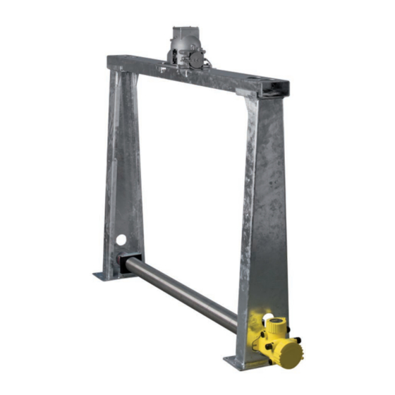
- Page 76 70 mm 70 mm (2.76") (2.76") Fig. 42: WEIGHTRAC 31 in the measuring frame with source container SHLD-1 (can be ordered separately) Maximum conveyor belt width Total width - Crossbeam Clear width (internal dimension) - measuring frame Total height - measuring frame...
- Page 77 (102.32 in) (92.8 in) (90.24 in) (107.99 in) 2800 mm 3198 mm 2971 mm 2775 mm 2710 mm 3000 mm (110.24 in) (125.91 in) (116.97 in) (109.25 in) (106.69 in) (118.11 in) WEIGHTRAC 31 • Four-wire 4 … 20 mA/HART...
-
Page 78: Industrial Property Rights
Les lignes de produits VEGA sont globalement protégées par des droits de propriété intellec- tuelle. Pour plus d'informations, on pourra se référer au site www.vega.com. VEGA lineas de productos están protegidas por los derechos en el campo de la propiedad indus- trial. Para mayor información revise la pagina web www.vega.com. - Page 79 Error messages 60 Protection class 24 Fault Radiation protection 12 – Rectification 63 Radiation safety officer 12 Fault rectification 63 Real value correction 58 Functional principle 9 Reference absorber 10 Relay 51 Repair 65 Gamma modulator 10 Replacement parts WEIGHTRAC 31 • Four-wire 4 … 20 mA/HART...
- Page 80 Totalizer 52 Type label 7 Unit - Belt speed 47 Unit of the pulse rate 38 Voltage supply 24, 73 Water cooling 22 X-ray alarm 45 Zero rate 40 Zero rate determination 53 WEIGHTRAC 31 • Four-wire 4 … 20 mA/HART...
- Page 81 Notes WEIGHTRAC 31 • Four-wire 4 … 20 mA/HART...
- Page 82 Notes WEIGHTRAC 31 • Four-wire 4 … 20 mA/HART...
- Page 83 Notes WEIGHTRAC 31 • Four-wire 4 … 20 mA/HART...
- Page 84 Subject to change without prior notice © VEGA Grieshaber KG, Schiltach/Germany 2021 VEGA Grieshaber KG Am Hohenstein 113 Phone +49 7836 50-0 77761 Schiltach E-mail: info.de@vega.com...
Need help?
Do you have a question about the WEIGHTRAC 31 and is the answer not in the manual?
Questions and answers