Advertisement
Quick Links
Advertisement

Summary of Contents for Logitech 200 MKIII Series
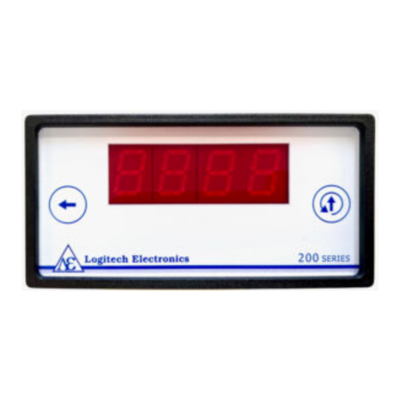
- Page 1 200 MKIII SERIES Tachometers Model 200T/DC User Guide...
-
Page 2: Specification
Specification Display 4 decade 7-segment high brightness red LED, 14mm high Display Update Programmable via display to 100ms, 250ms, 500ms or 1s Decimal point Programmable via display Scaling Programmable via display, retained in non-volatile memory. Signal inputs (A and B) Protected to 100V Standard sensitivity mode From 90mV @ 10Hz, 170mV @ 1kHz, 870mV @ 10kHz... -
Page 3: General Description
200 MKIII Series Tachometer with Alarm Outputs 200TA 200 MKIII Series Tachometer with Analogue Voltage/Current Output 200TAL 200 MKIII Series Tachometer with Analogue Voltage/Current & Alarm Outputs 200TD 200 MKIII Series Tachometer with Digital Output 200TDL 200 MKIII Series Tachometer with Digital & Alarm Outputs... - Page 4 Panel The panel has two touch switches, select and increment. The increment switch can also used to reset the count in the 200C (counter) and 200TC (combined tachometer and counter) models. Select Increment Protecting Settings (Tamper Protection) The touch switches can be disabled to prevent the unit’s settings from being modified. Once the lock is activated, it is not possible to change any of the units settings, or to adjust the sensitivity of the inputs.
- Page 5 Rear panel terminals Vs = supply voltage, passed through from power connector, or apply 12-30V DC to power unit 0V = 0V/ground passed through from power connector or connect to 0V if powering unit from rear terminals NC = No Connection Io (200TA/200TAL) = Analogue Current Output NC = No Connection Vo (200TA/200TAL) = Analogue Voltage Output...
-
Page 6: Programming The Instrument
Programming the instrument D = Displayed Value R = Rate (Frequency) Ra = Input A Rate Rb = Input B Rate S = Scaling Factor Choice of CALC setting For applications where a low number of pulses per second will be displayed as a speed (RPM etc) use multiplication mode (MUL) where D = R x S. - Page 7 Changing Settings On first power up from factory settings, the unit will enter set mode. Set Mode can also be accessed after initial configuration by holding the select touch button ← (A) and then pressing the increment touch button ↑ (B).
- Page 8 DSDP – Set display decimal point position [Default 1DP] Select the number of decimal points to display the scaled frequency value to. The decimal point position can be altered by pressing increment ↑. This limits the range of values that can be displayed. The unit will display “high” when the calculated value is greater than can be displayed on the number of digits available.
- Page 9 – (200TA/200TAL only) Set the reference (minimum) value for the analogue output. [Default 0.000] Enter the displayed (scaled) value, below which the analogue output will be at the minimum for the selected voltage/current range. Press select ← to select digit and increment ↑...
- Page 10 Sensitivity [Default 45] Press and hold the increment button ↑ (B), then press the select ← button (A) to enter sensitivity mode. The display will show SENS and then the current value is displayed. Sensitivity ranges from 0 (least sensitive) to 63 (most sensitive). Press select ←...
- Page 11 Variable Reluctance Magnetic Pickups Set input type (IPUT) to standard sensitivity (STD) or high sensitivity (HS) depending on target diameter and rotational speed. Connect the cable screen and one of the two wires from the magnetic pickup to the common 0V terminals (shown as the black wire below).
- Page 12 Electronic Sensors and Rotary Encoders Set input type (IPUT) to standard sensitivity (STD). The sensor/encoder can be supplied from the Vs terminal, provided that the sensor is rated to operate at this voltage. The sensor/encoder’s 0V connection should be made to any of the common 0V terminals, along with the cable screen if this is not connected to 0V at the sensor/encoder end.
-
Page 13: Warranty
Tachometers carry a two-year warranty that is only valid where there MKIII SERIES is no damage caused by accident, negligence, misapplication, or repairs/modifications attempted by unauthorised personnel. The warranty only extends to the original user. Copyright © Logitech Electronics Limited 2021-2022 Document No: 200T-MKIII_hb v1.4 August 2022...

