Table of Contents
Advertisement
Quick Links
Data sheet
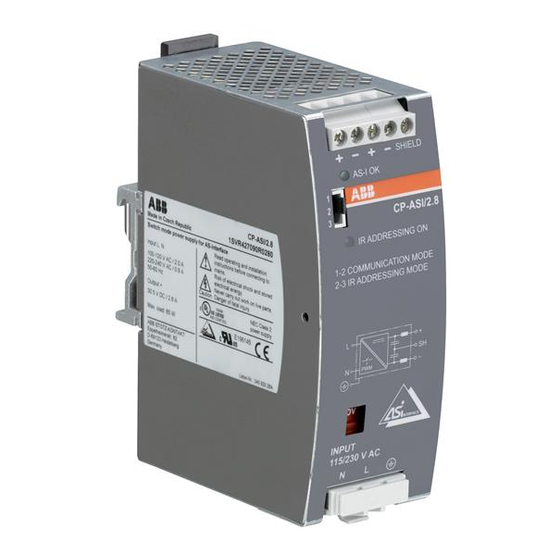
Power Supply CP-ASI/2.8
Primary switch mode power supply for AS-interface
The CP-ASI power supply range is specifically
designed with integrated data decoupling for the
supply of AS-Interface systems.
Up to 62 slaves (binary I/O devices) can be
supplied with a single two-conductor cable.
The configurable IR addressing mode allows the
easy assign of new ID addresses by means of an
external infrared programming unit.
Characteristics
–
Rated output voltage 30.5 V DC
–
Rated output current 2.8 A
–
Rated output power 85 W
–
Rated input voltage 115 or 230 V AC, configurable
–
Infrared addressing mode
–
High efficiency of up to 90.5 %
–
Low power dissipation and low heating
–
Free convection cooling (no forced cooling with
ventilators)
–
Ambient temperature range during operation -10...70 °C
–
Open-circuit, overload and short-circuit stable
–
Integrated input fuse
–
Tool-free mounting on DIN rail as well as demounting
–
LEDs for the indication of operational states
Order data
Type
Input voltage range
CP-ASI/2.8
85-132 V AC
184-264 V AC
Buy: www.ValinOnline.com | Phone 844-385-3099 | Email: CustomerService@valin.com
Approvals
A
H
Approvals refer to rated input voltage U
1)
Marks
a
Rated output voltage
Rated output current
30.5 V DC
2.8 A
UL 508, CAN/CSA C22.2 No.107.1
UL 60950-1, CAN/CSA C22.2 No. 60950-1
in
CE
Order code
1SVR427090R0280
1)
1)
Advertisement
Table of Contents

Related Manuals for ABB CP-ASI/2.8


Summary of Contents for ABB CP-ASI/2.8
- Page 1 Data sheet Power Supply CP-ASI/2.8 Primary switch mode power supply for AS-interface The CP-ASI power supply range is specifically designed with integrated data decoupling for the supply of AS-Interface systems. Up to 62 slaves (binary I/O devices) can be supplied with a single two-conductor cable.
-
Page 2: Operating Mode
Functions Output +, -, +, -, SHIELD: output terminals Indication of operational states AS-I OK: green LED – output voltage OK Configuration of operation mode Jumper Indication of operational states IR ADDRESSING ON: red LED – infrared addressing mode active Circuit diagram Input voltage selector Adjustment of input voltage... -
Page 3: Installation
Installation The device must be installed by qualified persons only and in accordance with the specific national regulations (e.g. VDE, etc.). The devices are maintenance-free chassis-mounted units. Before installation DANGER! Components with high stored energy and circuits with high voltage Danger to be electrocuted! Disconnect the system from the supply network and protect against switching on before any installation, maintenance or modification work. - Page 4 Mounting position The devices have to be mounted horizontally with the input terminals on the bottom. In order to ensure a sufficient convection, the minimum distance to other modules should not be less than 15 mm (0.59 in) in vertical and 25 mm (0.98 in) horizontal direction.
-
Page 5: High Current
Operation DANGER! High current Risk of electric arcs and electric shocks! Do not modify the installation (primary and secondary side). Intended use. CAUTION! Depending on the operation conditions the enclosure can become very hot Risk of burns! In order to ensure sufficient air-cooling the distance to other devices has to be considered. The device is intended for use as a primary switch mode power supply for AS-interface systems. -
Page 6: Technical Data
Technical data Data at T = 25 °C, U = 230 V AC and rated values, unless otherwise indicated Input circuit – Supply circuit L, N Rated input voltage U switch position 115 V 100-120 V AC switch position 230 V 220-240 V AC Input voltage range switch position 115 V... - Page 7 General data MTBF on request Power dissipation typ. < 9.1 W (230 V AC, 2.8 A) Efficiency typ. 90.5 % Duty time 100 % Dimensions (W x H x D) product dimensions 49 x 131 x 107 mm (1.93 x 5.16 x 4.21 in) packaging dimensions 151 x 65 x 140 mm (5.94 x 2.56 x 5.51 in) Weight...
- Page 8 Electromagnetic compatibility Interference immunity to IEC/EN 61000-6-2 electrostatic discharge IEC/EN 61000-4-2 Level 4 (8 kV / 15 kV) radiated, radio-frequency, electromagnetic field IEC/EN 61000-4-3 Level 3 (10 V/m) electrical fast transient/burst IEC/EN 61000-4-4 input circuit: Level 4 (4 kV) output circuit: Level 3 (2 kV) surge IEC/EN 61000-4-5 input circuit: L-L Level 3 (2 kV) / L-PE Level 4 (4 kV)
-
Page 9: Technical Diagrams
Technical diagrams Output behaviour Characteristic curve of output at T = 25 °C Temperature behaviour 70 T [°C] Characteristic curve of temperature at rated load Buy: www.ValinOnline.com | Phone 844-385-3099 | Email: CustomerService@valin.com... -
Page 10: Further Documentation
Instruction manual 1SVC 427 090 M0000 You can find the documentation on the internet at ABB Website -> Control Products -> Power Supplies. CAD system files You can find the CAD files for CAD systems at ABB Website -> Low Voltage Products &...