
Related Manuals for Altice Labs FGW GR140DG Wi-Fi 6


Summary of Contents for Altice Labs FGW GR140DG Wi-Fi 6
- Page 1 ALTICE LABS MANUAL – User Manual – FGW GR140DG Wi-Fi 6 GR140DG Document version 4.2-2 | 2020-10...
- Page 3 This document is for information purposes only and does not constitute a legally binding offer. The communication of the information contained in this document shall not oblige Altice Labs to supply the products and services identified and described herein. Altice Labs reserves the right to effect changes...
-
Page 5: Table Of Contents
1 Table of Contents 1 Table of Contents ........................5 Index of Figures ........................... 9 Index of Tables .......................... 11 2 FiberGateway ........................15 Summary ......................... 15 Technical Description ...................... 15 2.2.1 FiberGateway Main Functionalities ................15 2.2.2 FiberGateway Application Scenario ................. 16 2.2.3 Interoperability ...................... - Page 6 4.6.2 Mains connection and power up ................43 5 Configuration ........................45 Costumization ........................45 Software download from the OLT ................... 45 6 WebGUI ..........................47 General access ....................... 47 6.1.1 Equipment Menu ...................... 49 6.1.2 Functional Menu....................... 50 6.1.3 Main Window ......................
- Page 7 6.3.2.1 Dynamic DNS ....................91 6.3.2.2 UPnP ......................... 91 6.3.3 Tools ........................92 6.3.4 My account ....................... 94 6.3.4.1 User settings ..................... 94 7 Operational indicators ......................96 FiberGateway ........................96 7.1.1 LED Status Indicators ....................96 7.1.2 Troubleshooting FiberGateway ................98 8 Glossary ..........................
-
Page 9: Index Of Figures
Index of Figures Figure 1: FTTx architecture ......................16 Figure 2: Link Layer Configuration and Management ..............17 Figure 3: FiberGateway equipment Configuration ..............17 Figure 4: IP Based services-TR069 Configuration ..............18 Figure 5: Optical fiber Internet service user access ..............19 Figure 6: Stack of protocols for GPON architecture .............. - Page 10 Figure 46: Wi-Fi Security ......................71 Figure 47: Wi-Fi Security - Add MAC Filter ................. 72 Figure 48: Wi-Fi – Devices I ......................73 Figure 49: Wi-Fi – Devices II ....................... 73 Figure 50: Wi-Fi – Display filter ....................74 Figure 51: Wi-Fi –...
-
Page 11: Index Of Tables
Index of Tables Tabel 1: T-CONT types definition ....................26 Tabel 2: Alloc-ID's distribution by T-CONT type ................27 Tabel 3: Optical interfaces specifications ..................29 Tabel 4: FXS interface specifications FXS ................30 Tabel 5: WI-FI specification ......................31 Tabel 6: General Features...................... - Page 12 Index of Tables...
- Page 13 This User Manual is applicable to the equipment FiberGateway Altice GR140DG with the FCC ID: 2ACJF-FGW-GR140DG FCC NOTICE This device complies with FCC part 15 rules. Operation is subject to the following two conditions: 1. This device may not cause harmful interference and 2.
-
Page 15: Fibergateway
2 FiberGateway Summary The FiberGateway is an Optical Terminal Equipment (ONT) unit for Passive Optical Networks (PON) termination in a FTTH (Fiber-To-The-Home) service delivery architecture. FiberGateway communicates with the OLT (Optical Line Terminal) for the PON side and with the customer’s premises for the client side. -
Page 16: Fibergateway Application Scenario
2.2.2 FiberGateway Application Scenario The next figure shows a possible gateway scenario for FiberGateway equipments when in an FTTx architecture. Figure 1: FTTx architecture 2.2.3 Interoperability FiberGateway equipment complies with ITU-T G.984.x. recommendation as like as G.984.4 (OMCI) ensuring multi-vendor OLT interoperability with major GPON OLT vendors, as defined in BBF.247 ONU certification program. -
Page 17: Figure 2: Link Layer Configuration And Management
Network Topology OLT/ONT Management (TL1, SNMP) OMCI Figure 2: Link Layer Configuration and Management IP-based services Configuration and management is achieved by means of the TR-069 protocol as defined by Broadband Forum. This procedure takes for granted that previously the link layer connectivity has been achieved. -
Page 18: Interfaces
Subscriber Service Network Topology OLT/ONT Management (TL1, SNMP) TR069 OMCI Figure 4: IP Based services-TR069 Configuration 2.2.4 Interfaces Client interface options are of type: • 4x 10/100/1000Base-T for Ethernet network connection (RJ45 connectors); • 1x FXS channels (RJ11 connectors); Wi-Fi (dual-band concurrent): •... -
Page 19: Figure 5: Optical Fiber Internet Service User Access
access protocol (Time Division Multiple Access - TDMA). The OLT queues data to the various ONT terminals in order to provide time slot assignments for upstream communication. In Figure 5 it is shown a scenario for a multi-service user domain basic architecture through an ISP. Figure 5: Optical fiber Internet service user access In the upstream direction, the FiberGateway is connected to the optical splitter and respectively to the OLT through the PON port to provide integrated access services through the service headend. -
Page 20: Figure 6: Stack Of Protocols For Gpon Architecture
Figure 6: Stack of protocols for GPON architecture Several transmission containers (T-CONT) are assigned to each user. Each T-CONT has an associated GEM port and each GEM port has a VLAN identifier and an 802.1p priority level. The ONT classifies the traffic depending on the VLAN and the marked priority, and routes it over the corresponding T-CONT/GEM port. -
Page 21: General Architecture
General Architecture The GPON IC Processing unit is the core component inside FiberGateway. It is responsible for the interconnection and processing between client side interfacing and optical GPON Uplink interface. 2.4.1.1 GPON The FiberGateway GPON layer as G.984.x uses 1490nm downstream and 1310nm upstream of the optical wavelengh, with 2,488Gbps downstream and 1,244Gbps upstream by using an SC/APC protected optical connector. -
Page 22: Logical Interface (Vlan Encapsulation)
the PON network. FiberGateway equipments have the ability to deliver the Voice service over two types of interface: 2.4.1.4.2 Logical interface (VLAN encapsulation) If the FiberGateway has no FXS ports and the VoIP service is transparently forwarded from the OLT up to the Home Gateway (and vice versa) within a previously defined voice VLAN. -
Page 23: Figure 8: Fibergateway Circuit Block Diagram
Figure 8: FiberGateway circuit block diagram FiberGateway supports WI-FI, with a WIFI interface Functionalities: - 802.1x Authentication; External RADIUS Authentication; - WPA / WPA2 Protected access; 64/128 Bits WEP; - Cryptography; AES and TKIP encryption; - Wi-Fi multimedia support: WMM and WMM-PS; - Multiple profiles of SSIDs;... -
Page 24: Interfaces And Features
2.4.1.5.1 Interfaces and features - Concurrent mode 2.4GHz + 5GHz via 4 dual-band internal antennas - 2.4GHz: Compatible with IEEE 802.11b 1x1 SISO and 802.11g/n/ax 4x4 MIMO - 5GHz: Compatible with IEEE 802.11 a/n/ac/ax 4x4 MIMO - Channel bandwidth: 20, 40, 80 MHz - Multi User MIMO for best performance per user 2.4.1.5.2 Data Rates... -
Page 25: Upstream Qos
Figure 9: Dowstream QoS diagram In the downstream direction, Figure 9, the ingress traffic can be firstly classified. It passes by a policer and is configured to each ONT service, which is defined by one or two tags. It is remarked and policed per-CoS rate (port profile). -
Page 26: Dynamic Bandwidth Allocation (Dba)
Each of these Traffic Classes has an associated scheduler and policer. Queue management is performed based on Tail Drop or WRED. Then Traffic Classes to P-bit remarking is done and the traffic is sent to the uplink, Figure 11: Traffic distribution by service/client Figure 10: Upstream QoS diagram 2.6.3 Dynamic Bandwidth Allocation (DBA) -
Page 27: Upstream Qos Scenarios
Alloc-ID Allocation Type 0-127 Default Alloc-ID (Dynamic or Static) 128-255 Reserved 256-639 Dynamic or Static 640-1023 Static Tabel 2: Alloc-ID's distribution by T-CONT type Figure 11: Traffic distribution by service/client 2.6.4 Upstream QoS scenarios • 8 priority queues • Strict-priority •... -
Page 28: Technical Specifications
3 Technical specifications Interfaces 3.1.1 GPON The FiberGateway GPON G.984.x layer uses 1490nm downstream and 1310nm upstream optical wavelengths, with 2.488Gbps downstream and 1.244Gbps upstream by using an SC/APC protected optical connector 3.1.1.1 Optical Interfaces Items Unit FiberGateway Tx FiberGateway Tx Nominal bit rate Mbps 1244.16... -
Page 29: Ethernet
Items Unit Bit error ratio <-10 <-10 Minimum sensitivity Minimum overload Upstream optical penalty Consecutive identical digit >72 >72 immunity Tolerance to reflected optical <10 <10 power Tabel 3: Optical interfaces specifications 3.1.2 Ethernet Ethernet is the wired LAN technology and is revised in the IEEE 802.3 standard. At the OSI reference system, Ethernet is at the Data Link layer. -
Page 30: Wi-Fi
Minimum time of on-hook - register recognition of “on-hook” 150 msec recall/hook flash when hook-flash feature does not exist Minimum time “on-hook” on-hook - register 1100 msec recognition when hook- recall/hook flash Hook flash flash feature does exist minimum time “off-hook” off-hook 40 msec recognition... -
Page 31: General Features
Items Compliance Description Wireless 40bit secure key and 24 bit as defined in Security 802.11-2007 WPA2 encryption/de-encryption coupled to TKIP (as defined in 802.11-2007 and 802.1X) Short Guard SGI support Interval Space-Time STBC support Block Coding Transmit Power Up to +34dBm in the 2.4GHz band; (e.ir.p.) Up to +34dBm in the 5GHz band;... -
Page 32: General Service Description
Features FiberGateway OLT Interoperability (BBF.247) DHCP Client Number of GEM ports Number of T-CONT Primary Power Connection (VDC) 12 (± 15%) Primary Power Connection (VAC) 120V AC 60Hz ±2Hz AC/DC Adapter Max Power (W) European Code of Conduct on Energy AC/DC Adapter Energy Efficiency Consumption of External Power Supplies V5 U.S. -
Page 33: Optical Metering
VoIP > T.38 Fax Relay; > Caller ID and Call waiting; > Fax/Data Bypass; > RTP/RTCP packet > Echo Canceller; encapsulation; > Echo Canceller Length; > RFC 2833 support; > Jitter Buffer; > In-band signaling detection and > Caller ID Generation; generation (DTMF, call progress >... -
Page 34: Gpon/Ethernet Characteristics
Tabel 7: Wavelength planning In order to accomplish to that plan, the upstream wavelength for GPON must be restricted to ONU (ONT) equipment based on the ordinary DFB lasers, while the XGPON downstream signal range is defined from 1575 nm to 1580 nm and the XGPON upstream signal from 1260 nm to 1280 nm. For the coexistence of XGPON and GPON over the same fiber, the CO requires a WDM filter that combines the downstream signal (1490 nm, 1555 nm and 1577 nm), isolating the 1310 nm and 1270 nm upstream signal, with the video signal. -
Page 35: Gpon - Management
side, like, IPTV service VLAN, Internet Service VLAN (SVLAN and CVLAN), and VoIP Service VLAN; • 802.1 DSCP for CoS support; • IEEE 802.1Q and 802.1p support; • Multicast snooping support IGMPv2 and IGMPv3; • Firmware upgrade through the PON interface following the mechanisms specified in the ITU-T G.984.4 and G.988, including a safe dual firmware updates image system and the ability of back-up, allowing the SINGLE PORT FiberGateway start in case the software download fails, to enable a new software update. -
Page 36: Tabel 8: Standards Compliance
FCC CFR 47 Part 15 Subpart B Section 15.107 Conducted Emissions – Class B Emissions FCC CFR 47 Part 15 Subpart B Section 15.109 Radiated Emissions – Class B 2.4 GHz FCC CFR 47 Part 15 Subpart C Section 15.247 Radio 5 GHz FCC CFR 47 Part 15 Subpart E Section 15.407 (UNII-1) -
Page 37: Setup
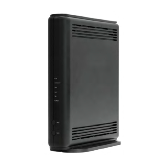
4 Setup Equipment Connectivity FiberGateway connections are located at the back side of the equipment; WPS and INFO (for status LEDS information) push buttons, are located at the front side of the equipment, Figure 12: FiberGateway connectivity general view Figure 12: FiberGateway connectivity general view Number Name Description... -
Page 38: Fibergateway Leds
Number Name Description button for 1second will start the association process. Energy saving button. In order to verify the status of all LEDS press the button. INFO If not pressed only POWER and Radio Signal LEDs (WPS, WIFI 5G and WIFI2.4G) have updated status information. -
Page 39: Typical Fibergateway Usage Scenario
Power supply OFF NOTES: To obtain these status LEDS information INFO button must be pressed. These status LEDS are always update (pressing INFO button is not required). Tabel 10: LEDs Status information LEDs Status Description ONT FiberGateway Status PON LINK 1. -
Page 40: Before Installing The Fibergateway Equipment
Figure 14: FiberGateway Typical usage scenario - Home network connections Connection Description RJ11 Telephone cable Ethernet Cable UTP CAT5,6 cable (direct or crossover) 12V DC Adapter Single-mode Optical Cable with SC/APC Connector (GPON) Wi-Fi Tabel 12: Connections description Before installing the FiberGateway equipment 4.4.1 Safety Warnings •... -
Page 41: Wireless Network Installation Best Practices
• The FiberGateway device is not designed for outdoor setup. Please place it in a convenient indoor/cabinet environment; • Use only the provided power kit. The use of a third party power adapter may not guarantee its proper operation; • To avoid eye hazard, never look directly into a fiber optic port or connector;... -
Page 42: Network Provider Connection
4.6.1 Network Provider Connection An Optical Patchcord (SM fibre ITU-T G.657B3) with connectors SC/APC, Figure 15: Network provider connection b), and Optical connector cleaning material will be required. Figure 15: Network provider connection • Clean the optical connectors of the optical pactchcord, Figure 15: Network provider connection •... -
Page 43: Mains Connection And Power Up
4.6.2 Mains connection and power up • Connect the power adaptor output connector to the 12-VDC power port on the equipment; • Plug the power adaptor appropriate power cord into an approved 100 to 230 VAC outlet, Figure 15: Network provider connection •... -
Page 45: Configuration
5 Configuration The equipment activation process has a distributed set of procedures that allow the connection of an inactive equipment to a PON network. This configuration is done following the procedure described in the OMCI protocol. Costumization For customization process, the requirements specified in the G.984.4, G.984.5 and ‘Implementer’s Guide’... - Page 46 A software image is divided into sections of 31 bytes, with one section per OMCC message and each section protected by the CRC of the OMCC. A group of sections makes up a window, and a group of windows constituting the image. Configuration...
-
Page 47: Webgui
6 WebGUI General access To configure the FiberGateway, you must place the network terminal, for example a personal computer, connected to the LAN, whose network configuration mode must be automatic. In this mode the personal computer will receive an IP address between 192.168.1.64/24 and 192.168.1.253/24 in addition to the other necessary network parameters. -
Page 48: Figure 17: Fibergateway Management Window
Fill in with username and password. • User: admin • Password: 123asd Choose the language to be used in the Web interface. After entering, the main window will be displayed that will be maintained throughout the session, a window that is structured in three areas, one of selection of equipment configurations, another of functionalities, and the third area is a work area where the various parameters of each of the selected configurations can be viewed and changed. -
Page 49: Equipment Menu
6.1.1 Equipment Menu This area, (area 1, Menu Equipment) located on the left side of the window, contains all the information about the equipment and its connectivity, is maintained throughout the session, allowing the selection of each item, showing window detailed information regarding the selected item. -
Page 50: Functional Menu
6.1.2 Functional Menu This area, (Area 2, Functional Menu), allows access to FiberGateway global features, and remains unchanged throughout the session. Figure 19: Functional Menu In the Home Functional Menu window you can access five windows namely: • Home Displays the network diagram allowing access to each of the network elements Internet Wi-Fi 2.4GHz Wi-Fi 5GHz... -
Page 51: Main Window
6.1.3 Main Window This window, Figure 21, shows all the information related to the menu item Equipment or Functional Menu selected, allowing its change. The initial window, after login in the equipment, shows a network diagram, being able to directly access each of the network elements making their selection. -
Page 52: Equipment Menu
Equipment menu The equipment menu contains six information / access fields: FGW FiberGateway, LAN Local Area Network, WAN Wide Area Network, Wi-Fi, Voice, Television 6.2.1 FGW FiberGateway Access to FiberGateway information is done by selecting the field next to the vertical blue line identified by FGW Fiber Gateway. -
Page 53: Figure 22: Information About Fibergateway
Figure 22: Information about FiberGateway Group Parameter Description Device Information Model Equipment model Ex:GR120DG FiberGateway IP address on LAN; Ex: LAN IPv4 Address 192.168.1.254 FiberGateway MAC Address; Ex: 00:06:91:1d:6e:c2 Uptime FiberGateway uptime; Ex: 2d 3h 32m 33s On/Off Connection status IPv4: 144.64.83.52 IPv6: 2001:8a0:ee8e:f100::1 Installed hardware version of... -
Page 54: Lan (Local Area Network)
6.2.2 LAN (Local Area Network) Access to LAN information and editing is done by selecting the field next to the vertical red line identified by LAN Local Area network. Figure 23: Equipment Menu – LAN After this selection, it shows in the work window more information (with possibility of editing), about LAN connectivity. -
Page 55: Figure 24: Lan (Local Area Network) - Caracteristics
Information about the DHCP server and the possibility of editing the various server parameters o IPv6 Information FiberGateway IPv6 addresses on the WAN interface o Interfaces LAN interface Ethernet states Figure 24: LAN (Local Area Network) – Caracteristics WebGUI... -
Page 56: Dhcp Server
6.2.2.1.1 DHCP Server The Dynamic Host Configuration Protocol (DHCP) server provides on-demand IP addresses to a terminal (host) in the local area network (LAN). In this window, Figure 26, you can configure the range of addresses to be assigned in the local network and the address lease time (in hours). In this example, whenever a terminal on the local network requests addresses using the DHCP protocol, the server will indicate that the Default gateway has the 192.168.1.254 address with a 24-bit mask (255.255.255.0);... -
Page 57: Ipv6 Information
6.2.2.1.2 IPv6 Information This window shows information about the IPv6 address, the IPv6 prefix, and the IPv6 Local-Link. These parameters can not be changed. The link-local is an IPv6 address built based on the FiberGateway MAC Address. Figure 26: IPv6 Information Group Parameter Description... -
Page 58: Devices
6.2.2.2 Devices This window, Figure 28 and following, shows all the devices installed on the local network. For each device there is a set of information; Host Name, Port Name, Status, MAC, IPv4, Lease Time, IPv6, Local IPv6 Link. Figure 28: LAN (Local Area Network) - Devices I Figure 29: LAN (Local Area Network) - Devices II Group Parameter... -
Page 59: Statistics
6.2.2.3 Statistics This window, shows the value of multiple counters in ethernet ports on the local network. Counters are grouped into two groups; received data and sent data. Figure 30: LAN (Local Area Network) - Statistics Group Parameter Description Statistics Interface LAN 1, LAN 2 Received... -
Page 60: Figure 32: Lan (Local Area Network) - Lease Estático Criar
Figure 32: LAN (Local Area Network) – Create Static Lease Group Parameter Description Create static lease Bridge where the static lease will be created. IP and Bridge mask are shown MAC address MAC address if interface IP address IP assigned to the interface Tabel 19: LAN (Local Area Network) –... -
Page 61: Wan Wide Area Network
6.2.3 WAN Wide Area Network Access to WAN information and editing is done by selecting the field next to the vertical blue line identified by the WAN Wide Area Network Figure 33: Equipment Menu - WAN The WAN selection on the left side of the window, the Equipment menu, Figure 34, shows in the main window more information, with possibility of editing, on WAN connectivity. -
Page 62: General Information
6.2.3.1.1 General information The general information consists of the following information fields; Interface, Service name, Internet connection, Service type, Firewall, IP address, Default gateway, Primary DNS, Secondary DNS. Figure 34: WAN (Wide Area Network) – General information Group Parameter Description General information Interface WAN Interface. -
Page 63: Optical Interface Information
Figure 35: WAN (Wide Area Network) – Informação IPv6 Group Parameter Description IPv6 Information IPv6 Pv6 status. On off IPv6 Address IPv6 Address IPv6 Prefix IPv6 Prefix Default gateway Default gateway Primary DNS Primary DNS Secondary DNS Secondary DNS Tabel 21: WAN (Wide Area Network) – IPv6 Information 6.2.3.1.3 Optical interface information The optical interface information consists of the following information fields;... -
Page 64: Statistics
Group Parameter Description Optical interface Link status Optical link state. On off Received optical Received optical power; Ex. -13,0 dBm power Transmited optical Transmited optical power; Ex. 4,0 dBm power Tabel 22: WAN (Wide Area Network) – Optical interface 6.2.3.2 Statistics This window shows the value of several counters in the WAN port, interface erouter0. -
Page 65: Routing Table
In this window you can perform two actions: refresh the page , and restart the counters. 6.2.3.3 Routing table This window shows the routing table. Figure 38: WAN (Wide Area Network) – Routing table Group Parameter Description Routing table Destination Interface WAN. -
Page 66: Wi-Fi
6.2.4 Wi-Fi Access to Wi-Fi information and editing is done by selecting the field next to the vertical blue line identified by Wi-Fi. Figure 39: Equipment Menu - Wi-Fi The Wi-Fi selection on the left side of the window, the equipment and connectivity menu, Figure 39, shows in the main window more information, with possibility of editing, about Wi-Fi connectivity. -
Page 67: Features
6.2.4.1 Features In the Features window it is possible to do the expansion of two connections namely; 2.4GHz - 802.11b/g/n/ax Network Settings and 5GHz - 802.11a/n/ac/ax Network Settings. Figure 41: Wi-Fi - Features On the outside of the FiberGateway there is a label with information on presets of the Wi-Fi interface, Figure 42. -
Page 68: Wi-Fi Settings
6.2.4.1.1 Wi-Fi Settings Area where you can view and edit Wi-Fi features, Figure 44. Feature settings: Smart Wi-Fi: A Smart Wi-Fi network consists of two or more nodes (FGW + N extender APs) that communicate with each other and work in a coordinated fashion to expand the Wi-Fi signal and ensure the best performance to each client / STA device according to their position. -
Page 69: Primary Network
6.2.4.1.1.2 Primary network The configuration parameters of the primary network are; Enable Network, SSID, SSID Announce, Network Authentication, Enable Wi-Fi Protected Setup (WPS), Encryption Mode, Password. Figure 44: Wi-Fi 2.4GHz and 5GHz – Primary Network Edition Group Parameter Description Largura de banda dos canais: 2.4GHz 5GHz network configuration Largura de banda... -
Page 70: Guest Network
6.2.4.1.1.3 Guest network The guest network allows the user to activate a network with a distinct LAN address, allowing a higher number of Wi-Fi devices. This is a wireless network distinct from the primary network, with another SSID and can be configured either as public (open) or as secure (password controlled access). -
Page 71: Security
6.2.4.2 Security In this window, Figure 46, all parameters relevant to the security of Wi-Fi access are configured by using filters that define which MAC addresses are authorized or disabled for either the primary network or the guest network in the two bands: Wi-Fi 2.4GHz and 5GHz Figure 46: Wi-Fi Security WebGUI... -
Page 72: 2.4Ghz / 5Ghz Mac Filtering
6.2.4.2.1 2.4GHz / 5GHz MAC Filtering 2.4GHz / 5GHz MAC filtering allows you to edit the control mode by selecting the "Edit" icon, and create a MAC filter by selecting the "+ Add MAC filter" Figure 47: Wi-Fi Security - Add MAC Filter The possible modes to configure are: Allowed - Means the rule will be used Blocked - Means the rule blocks... -
Page 73: Dispositivos
Group Parameter Description 2.4GHz / 5GHz MAC Primary network access control Disabled, allowed, blocked (s) Filtering list mode Network access control list mode Disabled, allowed, blocked (s) guest Create MAC filter Interface Interface Wi-Fi; 2.4GHz SSID Wi-Fi network name Endereço MAC Enter MAC address Tabel 27: Wi-Fi Security - Parameters 6.2.4.3... -
Page 74: Display Filters
Group Parameter Description Parameters Host Name of the connected terminal Port Wi-Fi port name: 2.4GHz / 5GHz Network Wi-Fi network name Status Status MAC address of the connected terminal IPv4 IPv4 address of the terminal Address type Address type Lease time IP address lease time IPv6 IPv6 address of the terminal... -
Page 75: Statistics
6.2.4.4 Statistics In this window, Figure 51, shows statistical data for bytes sent and received and packets and packages discarded (errors) on the Wi-Fi network in the two bands: Wi-Fi 2.4GHz and 5GHz. Figure 51: Wi-Fi – Statistics Group Parameter Description Interface Interface Wi-Fi: 2.4GHz 5GHz... -
Page 76: 5Ghz Neighbors
Figure 53: Neighbors 2.4GHz Group Parameter Description Neighbors 2.4GHz SSID Identification of access BSSID Physical address Channel Radio channel Bandwidth Radio channel bandwidth RSSI(dBm) Noise SNR(dB) Signal to noise ratio 802.11 Standard version Security WPA, WPA2, WEP, none Encription TKIP, AES, TKIP/AES Tabel 30: 2.4GHz Neighbors –... -
Page 77: Noise
Figure 54: Neighbors 5GHz Group Parameter Description Neighbors 5GHz SSID Identification of access BSSID Physical address Channel Radio channel Bandwidth Radio channel bandwidth RSSI(dBm) Noise SNR(dB) Signal to noise ratio 802.11 Standard version Security WPA, WPA2, WEP, none Encription TKIP, AES, TKIP/AES Tabel 31: 5GHz Neighbors - Parameters 6.2.4.6 Noise... -
Page 78: Ghz Noise
6.2.4.6.1 2.4GHz Noise In this window, the following figure shows the noise levels (dBm) in FiberGateway Wi-Fi channels, in the 2.4GHz band. Channel selection shows the noise value in dBm. Figure 56: 2.4GHz Noise 6.2.4.6.2 5GHz Noise In this window, Figure below, the noise levels (dBm) on FiberGateway Wi-Fi channels in the 5GHz band are shown. -
Page 79: Channel Capacity
6.2.4.7 Channel capacity In this window FiberGateway channel capacity are shown. Figure 58: Channel capacity 6.2.4.7.1 Channel capacity of 2.4GHz Figure 59: Channel capacity of 2.4GHz 6.2.4.7.2 Channel capacity of 5GHz Figure 60: Channel capacity of 5GHz WebGUI... -
Page 80: Voice
6.2.5 Voice Access to information and editing of the Voice service is done by selecting the field next to the vertical red line identified by Voice. Figure 61: Equipment Menu - Voice The Voice selection on the left side of the equipment window, Figure 61, shows in the main window more information about the Voice service, Figure 62. -
Page 81: Television
Group Parameter Description SIP Accounts Account status Registered / unregistered SIP account 1 On / Off Extension Voice service identification Display name Display name Authentication name SIP authentication name Password Access password Physical terminal Phone physical plug: FXS0, FXS1 Tabel 32: Voice - Parameters 6.2.6 Television The TV selection on the left side of the management window, equipment menu, Figure 63, shows in the... -
Page 82: Figure 64: Television - Details
Figure 64: Television - Details Group Parameter Description General information IPTV On/off Set top box Hostname Name of STB Interface Physical interface: LAN 1, LAN 2, Wi-Fi 5GHz primary MAC Address STB IP Address Tabel 33: Television - Parameters WebGUI... -
Page 83: Functional Menu
Functional Menu In this area (area 2, Functional Menu) we have the possibility to access five windows where parameters related to security, services, tools and access to My account can be viewed and edited. Figure 65: Functional Menu Selecting the Start window displays the following page: Figure 66: Functional Menu - Home In this window the following information is displayed: •... -
Page 84: Security
Also in this window is a set of quick connections to applications • Dynamic DNS • DMZ (Demilitarized Zone) • Firewall • Universal Plug’in’Play (UPnP) 6.3.1 Security This window, figure below, is displayed when the menu item Security is selected. Figure 67: Functional Menu - Security This window allows access to two new windows: Settings and Access In the Settings window you can view / change parameters in:... -
Page 85: Firewall And Dmz
• URL Filters • Firewall and DMZ The existing settings in the device are shown in each group. Figure 68: Functional Menu - Security Settings The Security Configuration, "Firewall and DMZ" is done directly in the security window, Settings, selecting the edit button and configuring its parameters. Setup is completed by using the save button visible on the right side of its security subgroup, Figure 69. -
Page 86: Access Window
Group Parameter Description Firewall and Flag: Enable firewall On – Active Firewall Off – Inactive Firewall Flag: Enable firewall IPv6 On – Active Firewall Off – Inactive Firewall Flag: Ativa/inativa DMZ On/Off On – DMZ active Off – DMZ inactive DMZ server DMZ Server IP Address Tabel 34: Security - Parameters... -
Page 87: Port Forwarding
6.3.1.2.1 Port forwarding In the port forwarding window it is possible to map internal and external ports. It means that it is possible for an external port to be routed to a different internal port. As is evident if no routing is done the internal port is equal to the external port. -
Page 88: Figure 72: Access - Create Port Forwarding Rule
Figure 72 hows all the possible fields to be changed, referring to port routing. To access this functionality, select the "+ create rule" field. The interface where these routing is done is the WAN interface eroute0. By selecting the "Service Name" field, a set of predefined applications is available, as well as the possibility of creating a new application. -
Page 89: Ports Activation
Group Parameter Description Port Forwarding Interface Identification of the WAN interface. Service Identification of the service Server IP address Service server address Protocolo Transport Protocol External ports External ports ID Internal ports ID of internal ports Tabel 35: Security - Port forwarding 6.3.1.2.2 Ports activation In the port activation window it is possible to activate internal and external ports and protocols (TCP,... -
Page 90: Services
Figure 74: Create port activation rule Group Parameter Description Ports activation Application name Application name Active protocol Active protocol Active ports Active ports Forwarding Protocol Forwarding Protocol Forwarding ports Forwarding ports Tabel 36: Security - Access 6.3.2 Services The selection of Services in the top functional menu, Figure 75, shows in the window more information, with possibility of editing, on the Configuration of Services. -
Page 91: Dynamic Dns
This window allows access to two new windows, Dynamic DNS, and UpnP. In this window you can access information related to services, define/change them. 6.3.2.1 Dynamic DNS Dynamic DNS (DDNS or Dynamic DNS) is a method of automatically updating a name server in Domain Name System (DNS). -
Page 92: Tools
Figure 77: UPnP - Enable Group Parameter Description UPnP Enable UPnP Enable / disable On/Off Tabel 38: UPnP – parameters 6.3.3 Tools The selection of Tools in the Functional Menu, Figure 78, shows in the main window more information, with the possibility of editing, about the Tools Configuration. Figure 78: Functional Menu - Tools You can restore FiberGateway with pre-set and stable settings (factory settings). -
Page 93: Figure 79: Tools - Resets
Figure 79: Tools - Resets Group Parameter Description Resets Restart the router Restart FiberGateway Restore default Reset original settings settings Resets original settings while maintaining client Partial restore default settings Tabel 39: Tools – Resets The software can be updated by selecting the respective file and pressing the symbol "upgrade" Figure 80: Tools –... -
Page 94: My Account
Figure 81: Tools – Diagnostics tools 6.3.4 My account This window, Figure 82, is displayed when the window header item, My Account, is selected. Figure 82: Functional Menu - My Account 6.3.4.1 User settings In this area it is possible to view and change the access parameters to FiberGateway. Selecting My Account from the Functional Menu, Figure 82, shows more information, with possibility of editing, on the User Account Setup in the main window, Figure 83. - Page 95 Group Parameter Description User role Profile chosen User settings User name admin Old password Enter old password New assword Enter new password Confirm password Re-enter new password Tabel 40: User settings The current version of FiberGateway only allows you to change the password. WebGUI...
-
Page 96: Operational Indicators
7 Operational indicators FiberGateway The FiberGateway has fourteen LEDs to indicate the operating status. 7.1.1 LED Status Indicators The following figure shows the location of the fourteen FiberGateway LEDs, Tabel 40 contains the description and meaning of each LED Figure 84: FiberGateway status LEDs Identification LEDs Status Description... -
Page 97: Tabel 41: Leds Status Information
Wi-Fi Radio Signal active WIFI Wi-Fi Radio Signal inactive Service configured and authenticated (green) Service not configured or registration failure Flashing Telephone off the hook Power supply ON (green) POWER Power supply OFF NOTES: To obtain these status LEDS information INFO button must be pressed. These status LEDS are always update (pressing INFO button is not required). -
Page 98: Troubleshooting Fibergateway
7.1.2 Troubleshooting FiberGateway The table below, according to the state of the LEDs, identifies a possible cause and describes the procedure to correct the problem. State Possible cause Solution - Check that the power cord is properly connected to the equipment and the No power supply for adapter to the electrical outlet. -
Page 99: Glossary
8 Glossary Alternating Current ITU-T International Telecommunication Union-Telecommunications Access Concentrator Local Area Network Advanced Encryption Standard Light Emitting Diode Autonomous System Media Access Control Access point Metropolitan Area Network AUTO-MDIX Medium Dependent Interface Crossover Automatic Choice MTBF Mean Time Between Failures Broadband Forum Optical Line Terminal CAT5E... - Page 100 Rua Eng. José Ferreira Pinto Basto 3810-106 Aveiro Portugal Tel.: +351 234 403 200 Fax: +351 234 424 723...
- Page 101 - Install this device in a site that meets the following conditions: - Temperature (41ºF - 104ºF) - Humidity (0% to 95%) DECLARATION OF CONFORMITY Aveiro - Portugal Rua Eng. José Ferreira Pinto Basto 3810 - 106 Aveiro (Portugal) www.alticelabs.com © 2020 Altice Labs. All rights reserved. August 2020 https://www.alticelabs.com/en/connectivity.html...
Need help?
Do you have a question about the FGW GR140DG Wi-Fi 6 and is the answer not in the manual?
Questions and answers