
Related Manuals for Altice Labs GR240BG


Summary of Contents for Altice Labs GR240BG
- Page 1 ALTICE LABS MANUAL FiberGateway User Manual GR240BG Document Version 4.1-5 | 2017-10...
- Page 3 FiberGateway User Manual...
- Page 4 This document is for information purposes only and does not constitute a legally binding offer. The communication of the information contained in this document shall not oblige Altice Labs to supply the products and services identified and described herein. Altice Labs reserves the right to effect changes...
-
Page 5: Table Of Contents
FiberGateway User Manual Contents List of figures ............................7 List of tables ............................9 Glossary ...............................11 1 Summary ............................17 2 Technical Description ........................19 FiberGateway Main Functionalities ....................19 FiberGateway Application Scenario ...................19 Interoperability ..........................20 Interfaces ............................21 General Features ........................21 General Architecture ........................24 GPON ............................24 Ethernet ............................24 IPTV ............................24... - Page 6 FiberGateway User Manual FiberGateway Setup ........................49 4.6.1 Network Provider Connection .....................50 4.6.2 Mains connection and power up ..................51 5 Configuration ...........................53 FiberGateway Activation ......................53 Costumization ..........................53 5.2.1 Software download from the OLT ..................53 6 Troubleshooting ..........................55 Contents...
-
Page 7: List Of Figures
FiberGateway User Manual List of figures Figure 1: FTTx architecture ........................19 Figure 2: Link Layer Configuration and Management ................20 Figure 3: FiberGateway equipment configuration ..................20 Figure 4: IP Based services-TR069 configuration ..................21 Figure 5: Optical fiber Internet service user access ................22 Figure 6: Stack of protocols for GPON architecture ................23 Figure 7: TR-142 Framework .........................23 Figure 8: FiberGateway system architecture ..................24... -
Page 9: List Of Tables
FiberGateway User Manual List of tables Table 1: T-CONT types definition ......................31 Table 2: Alloc-ID's distribution by T-CONT type ..................31 Table 3: Optical interfaces specifications ....................33 Table 4: FXS interface specifications .....................35 Table 5: Wi-Fi specification ........................36 Table 6: General Features........................37 Table 7: Standards compliance ......................41 Table 8: FiberGateway connectivity description ..................43 Table 9: LEDs Status information ......................45... -
Page 11: Glossary
FiberGateway User Manual Glossary Acronyms and abbreviations Third generation mobile telecommunications Authentication, Authorization, and Accounting Alternating Current Access Concentrator Access Control List Auto Configuration Server Advanced Encryption Standard Address Resolution Protocol Autonomous System AUTO-MDIX Medium Dependent Interface Crossover Automatic Choice Broadband Forum Border Gateway Protocol CAT5E... - Page 12 FiberGateway User Manual IEEE Institute of Electrical and Electronics Engineers IGMP Internet Group Management Protocol IP Multimedia Subsystem Internet Protocol IPTV Internet Protocol Television IPv4 Internet Protocol version 4 IPv6 Internet Protocol version 6 Internet Service Provider ITU-T Telecommunications International Telecommunication Union OSI Layer 2 OSI Layer 3 Local Area Network...
- Page 13 FiberGateway User Manual Subscriber Identity Module Session Initiation Protocol Session Initiation Protocol Server Message Block SNTP Simple Network Time Protocol Signalling System No. 7 SSID Service Set IDentifier Set Top Box Software T-CONT Transmission Container Transmission Control Protocol Time Division Multiplexing TDMA Time Division Multiple Access TKIP...
-
Page 15: Fcc Notice
FiberGateway User Manual This User Manual is applicable to the equipment FiberGateway Altice GR240BG with the FCC ID: 2ACJF-FGW-GR240BG FCC NOTICE This device complies with FCC part 15 rules. Operation is subject to the following two conditions: 1. This device may not cause harmful interference and 2. -
Page 17: Summary
FiberGateway User Manual 1 Summary The FiberGateway is an Optical Terminal Equipment (ONT) unit for Passive Optical Networks (PON) termination FTTH (Fiber-To-The-Home) service delivery architecture. FiberGateway communicates with the OLT (Optical Line Terminal) for the PON side and with the customer’s premises for the client side. -
Page 19: Technical Description
FiberGateway User Manual 2 Technical Description FiberGateway Main Functionalities The FiberGateway is aimed for customer premises and complies with the ITU-T G.984.x recommendation in order to transport (over GPON) and deliver (to premises domain) the full broadband service pack. Broadband service applications are commonly referred as below: •... -
Page 20: Interoperability
FiberGateway User Manual Interoperability FiberGateway equipment complies with ITU-T G.984.x. recommendation as like as G.984.4 (OMCI) ensuring multi-vendor OLT interoperability with major GPON OLT vendors, as defined in BBF.247 ONU certification program. BBF.247 ONU certification program certifies ONT link layer configuration and management protocol, OMCI, Figure 2, as defined by ITU-T G.984.3, ITU-T G.984.4 and ITU-T G.988. -
Page 21: Interfaces
FiberGateway User Manual Subscriber Service Network Topology OLT/ONT Management (TL1, SNMP) TR069 OMCI Figure 4: IP Based services-TR069 configuration Interfaces Client interface options are of type: • 4x 10/100/1000Base-T for Ethernet network connection (RJ45 connectors); • 2x FXS channels (RJ11 connectors); •... -
Page 22: Figure 5: Optical Fiber Internet Service User Access
FiberGateway User Manual Figure 5: Optical fiber Internet service user access In the upstream direction, the FiberGateway is connected to the optical splitter and respectively to the OLT through the PON port to provide integrated access services through the service headend. In the downstream direction, the FiberGateway is connected to various terminals through the following LAN-side ports to implement multi-play services: •... -
Page 23: Figure 6: Stack Of Protocols For Gpon Architecture
FiberGateway User Manual Figure 6: Stack of protocols for GPON architecture Several transmission containers (T-CONT) are assigned to each user. Each T-CONT has an associated GEM port and each GEM port has a VLAN identifier and an 802.1p priority level. The ONT classifies the traffic depending on the VLAN and the marked priority, and routes it over the corresponding T-CONT/GEM port. -
Page 24: General Architecture
FiberGateway User Manual General Architecture FiberGateway basic system architecture is hereafter presented. Figure 8: FiberGateway system architecture The GPON IC Processing unit is the core component inside FiberGateway. It is responsible for the interconnection and processing between client side interfacing and optical GPON Uplink interface. GPON The FiberGateway GPON layer as G.984.x uses 1490nm downstream and 1310nm upstream of the optical wavelengh, with 2,488Gbps downstream and 1,244Gbps upstream by using an SC/APC... -
Page 25: 2.10 Voice
FiberGateway User Manual the FiberGateway will send to OLT a IGMP packet requesting that Channel. The FiberGateway is also responsible for implementing the snooping for the channels that the user requests. 2.10 Voice 2.10.1 Supported VoIP specifications: • Call control: SIPv1/v2; •... -
Page 26: 2.11 Wi-Fi
FiberGateway User Manual The FiberGateway will allow VoIP or NGN (Next Generation Network) traffic from devices connected to the RJ11 or RJ45 interfaces, towards the same internal VLAN. Apart of the SIP and Megaco (H.248) self-configuration, it is also possible to make modifications in the voice service configurations by updating the FiberGateway SW through download from the OLT via OMCI. -
Page 27: Operational Description
FiberGateway User Manual Figure 9: FiberGateway circuit block diagram 2.11.2 Operational Description The FiberGateway supports Wi-Fi, with Wi-Fi interfaces operating in the 2.4GHz and 5GHz frequencies The FiberGateway complies with the following standards: • IEEE 802.11a (5GHz, up to 54 Mbps) •... -
Page 28: Interfaces And Features
FiberGateway User Manual The ONT supports the following features: • wireless security WEP encryption (64/128 bits) WPA (Wireless Protect Access) TKIP WPA2 AES WPA2 mixed 802.1x Authentication External RADIUS Authentication Client access control through media access control (MAC) filter Dynamic cryptography (TKIP and AES) Multiple SSIDs Profiles WPS (Pushbutton and PIN entry);... -
Page 29: Policing/Rate Limiting
FiberGateway User Manual 2.13 Policing/Rate Limiting 2.13.1 Downstream QoS The OLT system supports traffic classification at the ingress ports (ETH, LAGs, PON, etc) based on P- Bits, IP DSCP and IP. The OLT system provides several QoS mechanisms, that can be targeted to the flow characterized by one or two VLAN according with the type of service, or can be targeted to the packets priority, where each p-bit/DSCP is mapped in one of eight queues of each port. -
Page 30: Upstream Qos
FiberGateway User Manual 2.13.2 Upstream QoS Figure 11: Upstream QoS diagram In the upstream, Figure 11, for each T-CONT DBA the ingress traffic in the ONT passes by a mapping block that maps the traffic in one of the eight queues according with the p-bit, (in case the ingress traffic is untagged a DSCP->p-bit mapping is performed). -
Page 31: Figure 12: Traffic Distribution By Service/Client
FiberGateway User Manual Table 1: T-CONT types definition T-CONT Type 1 Type 2 Type 3 Type 4 Type 5 Units Fixed BW- R [b/s] Assured BW- R [b/s] Max Bw - R > R > [b/s] Bandwidth Non-Assured Best-Effort Eligibility BW - R In each GPON interface there are 1024 Alloc-ID (T-CONT identifiers) available, provided to manage ONT services. -
Page 32: Upstream Qos Scenarios
FiberGateway User Manual 2.13.4 Upstream QoS scenarios • 8 priority queues • Strict-priority • Upstream Scheduling: Strict Priority (currently supported) Strict Priority + rate controller (currently supported) Strict Priority + WFQ (can be SW supported) Technical Description... -
Page 33: General Specifications
FiberGateway User Manual 3 General Specifications Interfaces 3.1.1 GPON The FiberGateway GPON G.984.x layer uses 1490nm downstream and 1310nm upstream optical wavelengths, with 2.488Gbps downstream and 1.244Gbps upstream by using an SC/APC protected optical connector 3.1.1.1 Optical Interfaces Table 3: Optical interfaces specifications Items Unit FiberGateway Tx... -
Page 34: Ethernet
FiberGateway User Manual Items Unit Minimum sensitivity Minimum overload Upstream optical penalty Consecutive identical digit >72 >72 immunity Tolerance to reflected optical <10 <10 power 3.1.2 Ethernet Ethernet is the wired LAN technology and is revised in the IEEE 802.3 standard. At the OSI reference system, Ethernet is at the Data Link layer. -
Page 35: Fxs
FiberGateway User Manual 3.1.3 Table 4: FXS interface specifications Items State Description DC voltage (V) 48V (21 to 56.5V) According to ANSI/TI A-1063 DC offset: ≥ 15 Vdc AC voltage: ≥ 55 Vac rms Ringer voltage (V) Max Voltage: 100 Vp Frequency: 20Hz +/- 3% Ringing signal normal ringing... -
Page 36: Wi-Fi
FiberGateway User Manual 3.1.4 Wi-Fi Table 5: Wi-Fi specification Items Compliance Description IEEE 802.11 b/g/n/ac Bit Rates 802.11 b/g Up to 11Mbps (IEEE802.11b) Up to 54Mbps (IEEE802.11g) 802.11 n Up to 600Mb/s over four spatial streams in the 2.4GHz band; Up to 600Mb/s over four spatial streams in the 5GHz band 802.11 ac... -
Page 37: General Features
FiberGateway User Manual Items Compliance Description Mode n/2.4GHz (10% PER) 1Mb/s: -96dBm 54Mb/s: -75dBm M0/20MHz: -88 dBm M0/40MHz: -85 dBm M7/20MHz: -66 dBm M7/40MHz: -63 dBm Mode n/5GHz (10% PER) 6Mb/s: -89 dBm 54Mb/s: -74 dBm M0/20MHz: -87 dBm M0/40MHz: -83 dBm M7/20MHz: -64 dBm M7/40MHz: -61 dBm Mode ac/5GHz (10% PER) -
Page 38: General Service Description
FiberGateway User Manual Features FiberGateway AC/DC Adapter Max Power (W) European Code of Conduct on Energy Consumption of External Power Supplies V5 AC/DC Adapter Energy Efficiency U.S. Department of Energy (DoE) Level VI European Code of Conduct on Energy Consumption of Broadband Equipment V6 Energy Efficiency Energy Star - Small Network Equipments v1.0 MTBF (h) -
Page 39: Optical Metering
FiberGateway User Manual > T.38 Fax Relay; > Caller ID and Call waiting; VoIP > Fax/Data Bypass; > RTP/RTCP packet > Echo Canceller; encapsulation; > Echo Canceller Length; > RFC 2833 support; > Jitter Buffer; > In-band signaling detection and >... -
Page 40: Gpon/Ethernet Characteristics
FiberGateway User Manual Figure 13: Wavelength planning In order to accomplish to that plan, the upstream wavelength for GPON must be restricted to ONU (ONT) equipment based on the ordinary DFB lasers, while the XGPON downstream signal range is defined from 1575 nm to 1580 nm and the XGPON upstream signal from 1260 nm to 1280 nm. For the coexistence of XGPON and GPON over the same fiber, the CO requires a WDM filter that combines the downstream signal (1490 nm, 1555 nm and 1577 nm), isolating the 1310 nm and 1270 nm upstream signal, with the video signal. -
Page 41: Standards
FiberGateway User Manual OLT side, like, IPTV service VLAN, Internet Service VLAN (SVLAN and CVLAN), and VoIP Service VLAN; • 802.1 DSCP for CoS support; • IEEE 802.1Q and 802.1p support; • Multicast snooping support IGMPv2 and IGMPv3; • Firmware upgrade through the PON interface following the mechanisms specified in the ITU-T G.984.4 and G.988, including a safe dual firmware updates image system and the ability of back-up, allowing the SINGLE PORT FiberGateway start in case the software download fails, to enable a new software update. -
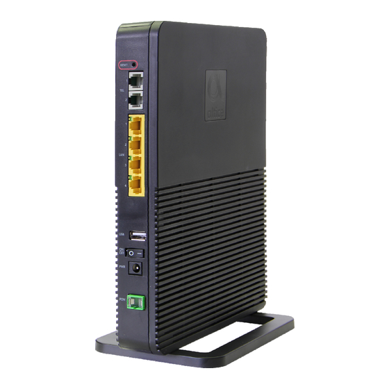
Page 43: Setup
FiberGateway User Manual 4 Setup Equipment Connectivity FiberGateway connections are located at the back side of the equipment; WPS and INFO (for status LEDS information) push buttons, are located at the front side of the equipment, Figure 17. Figure 14: FiberGateway connectivity general view Table 8: FiberGateway connectivity description Number... - Page 44 FiberGateway User Manual Number Name Description 12V DC Power Supply Connector Equipment Optical port GPON; SC/APC Wi-Fi Protected Set-up Button; • Switches on/off Wi-Fi if pressed for 5 seconds • With the Wi-Fi interface on, in order to connect a device the interface, pressing the WPS button for 1second will start the association process.
-
Page 45: Fibergateway Leds
FiberGateway User Manual FiberGateway LEDs Figure 15: FiberGateway Status LEDs Table 9: LEDs Status information Identification LEDs Status Description With Ethernet connection (green) A1 a A4 No Ethernet connection Flashing Ethernet IN/OUT activity (green) With Internet connection (green) INTERNET Inactive port Flashing Internet IN/OUT activity (green) PON LINK... -
Page 46: Typical Fibergateway Usage Scenario
FiberGateway User Manual WPS active (blinking green) WPS inactive Wi-Fi Radio Signal active WIFI 5GHz Wi-Fi Radio Signal inactive Wi-Fi Radio Signal active WIFI 2.4GHz Wi-Fi Radio Signal inactive Service configured and authenticated (green) A12, A13 TEL1, TEL2 Service not configured or registration failure Flashing Telephone off the hook Power supply ON (green) -
Page 47: Before Installing The Fibergateway Equipment
FiberGateway User Manual Figure 16: FiberGateway Typical usage scenario -Home network connections Connection Description RJ11 Telephone cable Ethernet Cable UTP CAT56 cable (direct or crossover) 12V DC Adapter Single-mode Optical Cable with SC/APC Connector (GPON) Wi-Fi Before installing the FiberGateway equipment 4.4.1 Safety Warnings •... -
Page 48: Wireless Network Installation Best Practices
FiberGateway User Manual • The FiberGateway device is not designed for outdoor setup. Please place it in a convenient indoor/cabinet environment; • Use only the provided power kit. The use of a third party power adapter may not guarantee its proper operation;... -
Page 49: Fibergateway Setup
FiberGateway User Manual Table 11: FiberGateway connections description Number Name Description RESET Configuration RESET button 2x RJ11 – FXS Ports TEL (1, 2) 4x RJ45 Ports - 10/100/1000Base-T Ethernet with LAN (1, 2, 3, 4) AUTO-MDIX 1x USB 2.0 port ON/OFF button 12V DC Power Supply Connector Equipment Optical port GPON;... -
Page 50: Network Provider Connection
FiberGateway User Manual Connection 18, b) Optical connector cleaning kit Ethernet cables CAT6 568B Home Network RJ11 Telephone Cable Connections Device with Wi-Fi connectivity (laptop/smartphone/ …) (1) Depending on the ordered model (2) Home network scenario dependent 4.6.1 Network Provider Connection An Optical Patchcord (SM fibre ITU-T G.657B3) with connectors SC/APC, Figure 18, b), and Optical connector cleaning material will be required. -
Page 51: Mains Connection And Power Up
FiberGateway User Manual • Accommodate the patchcord excessive length avoiding small bend radius on the patchcord (30mm minimum bend radius). 4.6.2 Mains connection and power up • Connect the power adaptor output connector to the 12-VDC power port on the equipment; •... -
Page 53: Configuration
FiberGateway User Manual 5 Configuration Configuration of the FiberGateway equipment is done remotely, using OMCI and TR-069. FiberGateway Activation The equipment activation process has a distributed set of procedures that allow the connection of an inactive equipment to a PON network. This configuration is done following the procedure described in the OMCI protocol. - Page 54 FiberGateway User Manual • Commit image It selects a valid SW image to be loaded and executed by default when the FiberGateway is restarted; • Composition of the Software Image A software image is divided into sections of 31 bytes, with one section per OMCC message and each section protected by the CRC of the OMCC.
-
Page 55: Troubleshooting
FiberGateway User Manual 6 Troubleshooting The table below, according to the equipment LEDs’ status, (Table 9, Table 10), identifies a possible cause and describes the procedure to fix the problem. Table 13: Troubleshooting Procedures State Possible Cause Solution • Check that the power cable is correctly connected to both the No power supply to equipment and the adapter at the... - Page 56 Rua Eng. José Ferreira Pinto Basto 3810-106 Aveiro Portugal Tel.: +351 234 403 200 Fax: +351 234 424 723...
Need help?
Do you have a question about the GR240BG and is the answer not in the manual?
Questions and answers