
Related Manuals for ABB 4630


Summary of Contents for ABB 4630
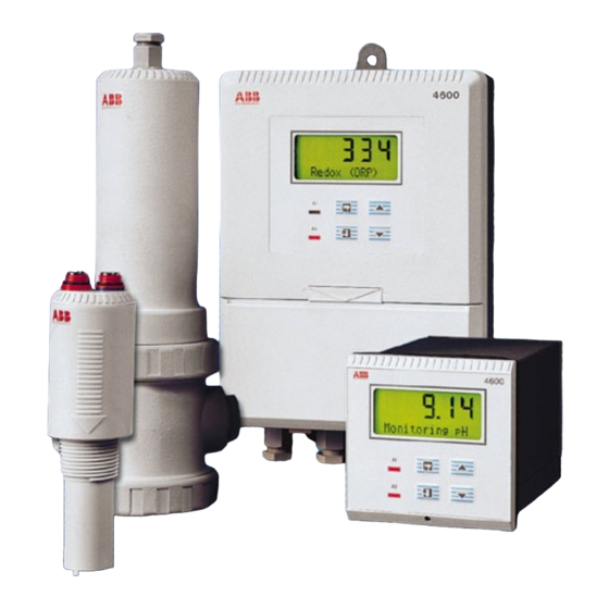
- Page 1 (ORP) Analyzers Operating Instructions IM/4600–PH_12 Models 4630 & 4635 (incorporating Water Wash Versions 4631 & 4636)
- Page 2 Cert. No. Q 05907 As a part of ABB, a world leader in process automation technology, we offer customers application expertise, service and support worldwide. EN 29001 (ISO 9001) We are committed to teamwork, high quality manufacturing, advanced technology and unrivalled service and support.
-
Page 3: Table Of Contents
CONTENTS Section Page Section Page INTRODUCTION ............2 PROGRAMMING ............22 Access to Secure Parameters ......24 PREPARATION ............2 Language Page ..........24 Checking the Code Number ......2 Set Up Parameters Page ........ 24 2.1.1 Wall-/Pipe-mounted Instruments ..2 Set Up Alarms Page ........ -
Page 4: Introduction
(Wall- /Pipe-mounted Model) The 4630/31 models are wall- or pipe-mounted instruments 4630-31/500 and the 4635/36 models are panel-mounted, DIN sized instruments. All instruments have a single programmable pH input channel, and a single temperature input channel. -
Page 5: Mechanical Installation
3 MECHANICAL INSTALLATION 3.1 Siting Requirements Caution. • Mount in a location free from excessive vibration. Maximum Distance Electrode • Mount away from harmful vapours and/or dripping fluids. 100m Information. It preferable mount instrument at eye level, allowing an unrestricted view of A –... -
Page 6: Mounting
…3 MECHANICAL INSTALLATION 3.2 Mounting 3.2.1 Wall-/Pipe-mounted Instruments – Figs. 3.2 and 3.3 Dimensions in mm (in) (1.65) 68 (2.68) 160 (6.3) (8.43) (9.13) (9.84) Allowance for 69 (2.72) 200 (7.9) Cable Bends 61 (2 ) O.D. Vertical or Horizontal Post Fixing Centres Fig. -
Page 7: Panel-Mounted Instruments
3 MECHANICAL INSTALLATION …3.2 Mounting 3.2.2 Panel-mounted Instruments – Figs. 3.4 and 3.5 Dimensions in mm (in) +0.8 +0.03 (3.62 96 (3.78) 12 (0.47) 191 (7.52) –0 –0 +0.8 –0 Panel Cut-out +0.03 (3.62 (3.78) –0 Fig. 3.4 Overall Dimensions Cut a hole in the panel (see Fig. -
Page 8: Electrical Connections
4 ELECTRICAL CONNECTIONS Warning. Before making any connections, ensure that the power supply, any high voltage-operated control circuits and high common mode voltages are switched off. 4.1 Access to Terminals 4.1.1 Wall-/Pipe-mounted Instruments – Fig. 4.1 Remove protection cover slide down Slacken captive... -
Page 9: Connections, General
4 ELECTRICAL CONNECTIONS… 4.2 Connections, General Information. • Earthing (grounding) – stud terminal(s) is fitted to the transmitter case for bus-bar earth (ground) connection – see Fig. 4.1 or 4.5. • Cable routing – always route signal output/pH electrode cable leads and mains-carrying/relay cables separately, ideally in earthed metal conduit. - Page 10 …4 ELECTRICAL CONNECTIONS l l a o l l o l l Note. Electrodes are currently designed to give a reading that is compatible with analog instruments. To obtain correct readings with the 2867 electrode system, the electrode leads need to be reversed as shown. Table 4.1 Cable Colors for Different pH Electrode System Types...
-
Page 11: Connections - Wall-/Pipe-Mounted Instruments
4 ELECTRICAL CONNECTIONS… 4.3 Connections – Wall-/Pipe-mounted Instruments – Fig. 4.4 Note. Refer to Fig. 4.1 for Access to Terminals. Caution. Slacken terminal screws fully before making connections. 5 6 7 – Channel 1 Channel 2 Retrans. Relay 1 Power Serial/Modbus output Relay 2... -
Page 12: Connections - Panel-Mounted Instruments
…4 ELECTRICAL CONNECTIONS 4.4 Connections – Panel-mounted Instruments – Fig. 4.5 Note. Refer to Fig. 4.1 for Access to Terminals. Caution. Slacken terminal screws fully before making connections. Earth Stud Retransmission RS422/RS485 output Rx– – Retrans output Serial (if fitted) Interface Tx–... -
Page 13: Selecting The Mains Voltage
4 ELECTRICAL CONNECTIONS 4.5 Selecting the Mains Voltage 4.5.1 Wall-/Pipe-mounted Instruments – Fig. 4.6 Remove cap Information. Use a small, and screw flat-bladed screwdriver to remove the screw cap from the case. Remove front panel Slacken captive screws and remove protection cover Select the mains voltage required... -
Page 14: Controls And Displays
5 CONTROLS AND DISPLAYS 5.1 Displays – Fig. 5.1 The display comprises a 5-digit, 7-segment digital upper Advance to next page display line and a 16-character dot-matrix lower display line. The upper display line shows actual values of pH, Page 1 Page 2 temperature, alarm set points or programmable parameters. -
Page 15: Operation
6 OPERATION 6.1 Instrument Start-up Ensure all electrical connections have been made correctly and switch on the power supply. If the instrument is being commissioned for the first time its parameters must be programmed, as detailed in Section 7, before carrying out a pH Calibration. 6.2 Operation –... -
Page 16: Operating Page
…6 OPERATION 6.2.1 Operating Page Measured pH 7 0 0 The measured pH is displayed. Monitoring pH If the Water Wash cycle is selected (Models 4631 or 4636 only), an alternative message, WASH IN PROCESS WASH IN PROCESS, is displayed. The Alarm 1 status and the retransmission value are held in their pre-cycle condition for the duration of the wash cycle. - Page 17 6 OPERATION… …6.2.1 Operating Page Continued from previous page. Slope Value: l 0 0 0 . a value between the programmed minimum % slope value (see pH Calibration Minimum in the on page 25) and 105% should be displayed. Slope Value Set Up Parameters Page % Slope Value If the value is outside these limits the electrode system must be checked.
-
Page 18: Single Point Ph Calibration
…6 OPERATION 6.2.2 Single Point pH Calibration A single point calibration may be carried out in preference to a two point calibration provided a two point calibration has been carried out since installing the instrument. This procedure assumes an electrode pair with perfect Nernstian response, i.e. 59.16mV per pH change at 25°C. -
Page 19: Two-Point Ph Calibration (Automatic Mode)
6.2.3 Two-point pH Calibration (Automatic Mode) An automatic pH calibration involves standardizing the instrument and electrode system using ABB supplied buffer solutions or non-ABB buffer solutions of 4, 7, 9 and 10pH. Before starting pH calibration, check the Temp Comp setting in the Set Up –... - Page 20 2 must be set to either 9 or 10pH. Buffer 1 Calibration – – – – – Immerse the electrode and temperature compensator in either the ABB 4pH buffer solution or the non-ABB buffer 1 solution selected earlier. Immerse Buffer 1 Advance to initiate calibration.
-
Page 21: Two-Point Ph Calibration (Manual Mode)
6 OPERATION… 6.2.4 Two-point pH Calibration (Manual Mode) A manual pH calibration involves standardizing the instrument and the electrode system using any two suitable buffer solutions which give a reasonable span and encompass the anticipated measuring range. Before starting pH calibration, check the Temp Comp setting in the –... - Page 22 …6 OPERATION …6.2.4 Two-point pH Calibration (Manual Mode) Continued from previous page Calibration Message – – – – – Refer to Table 6.3 below for calibration messages clarification. If the calibration has failed, advance to the next two parameters for diagnostic information. (Calibration Message) Advance to next parameter.
-
Page 23: Operation - Redox (Orp) Measurement Mode
6 OPERATION 6.3 Operation – Redox (ORP) Measurement Mode Operation in the Redox measurement mode comprises an operating page only. The is a general use page in which Operating Page parameters can be viewed but not altered. To alter or program a parameter refer to the programming pages in Section 7. 6.3.1 Operating Page Measured mV 2 5 0... -
Page 24: Programming
7 PROGRAMMING... - Page 25 7 PROGRAMMING…...
-
Page 26: Access To Secure Parameters
…7 PROGRAMMING 7.1 Access to Secure Parameters Security Code 0 0 0 0 0 Enter the required code number, between 00000 and 19999, to gain access to the secure parameters. If an incorrect value is entered, access to subsequent programming SECURITY CODE pages is prevented and the display reverts to the Operating Page. - Page 27 7 PROGRAMMING… …7.3 Set Up Parameters Page Continued from previous page. Temperature Units: – – – – – can be displayed as either degrees Celsius or Fahrenheit. Temp Units (°C) Select either (°C) or (°F). (°F) Antimony Electrode Temperature Compensation –...
-
Page 28: Set Up Alarms Page
…7 PROGRAMMING 7.4 Set Up Alarms Page – press to advance to next parameter – – – – – – press to advance to next page. SET UP ALARMS These two keys are used to advance to all subsequent parameters and pages. If a parameter is changed it is automatically stored on operation of either key. - Page 29 7 PROGRAMMING… …7.4 Set Up Alarms Page Continued from previous page Water Wash (4631/4636 only) /Alarm 2 Action – – – – – To select the Water Wash cycle press the key until Water Wash is displayed. Water Wash To select Alarm 2 Type, press the key until A2 Type is displayed, then repeat as A2 Type Fail...
-
Page 30: Set Up Retransmission Page
…7 PROGRAMMING 7.5 Set Up Retransmission Page – press to advance to next parameter – – – – – – press to advance to next page. SET UP RETRANS These two keys are used to advance to all subsequent parameters and pages. If a parameter is changed it is automatically stored on operation of either key. - Page 31 …7.5 Set Up Retransmission Page Continued from previous page. Retransmission 2 Page header – – – – – Note. The second retransmission output is available only on 4630/800, 4631/800, SET UP RETRANS 2 4635/800 and 4636/800 instruments. Retransmission 2 Output Current Range –...
-
Page 32: Calibration
8 CALIBRATION Note. The instrument is calibrated by the Company prior to despatch and recalibration should be carried out only if the instrument's accuracy is suspect and suitably calibrated test equipment is available. 8.1 Equipment Required a) Millivolt source (pH or Redox input simulator, if required) –1000 to +1000mV. b) Decade resistance box (PT100 input simulator): 0 to 1kΩ... -
Page 33: Factory Settings Page
8 CALIBRATION… 8.3 Factory Settings Page xxxxx When carrying out the electrical calibration procedure, the actual values denoted by are unimportant and are used only to determine display reading stability. – – – – – FACTORY SETTINGS Factory Settings Access Code 0 0 0 0 0 Enter the required code number, between 00000 and 19999, to gain access to the factory settings. - Page 34 Set Up Retransmission Page not affect the reading. Advance to next parameter. Adjust Retransmission 2 Zero (available only on 4630/800, 4631/800, 4635/800 and – – – – – 4636/800 instruments) Adjust RTX Zero2 Set the milliammeter reading to 4mA.
-
Page 35: Simple Fault Finding
9 SIMPLE FAULT FINDING 9.1 Error Messages b) Use the simulator to carry out an impedance check on the transmitter, i.e. glass to reference, glass to earth and If erroneous or unexpected results are obtained the fault may be indicated by an error message – see Table 9.1. However reference to earth –... -
Page 36: Specification
Model 4635/36 panel-mounting. Retransmission No. of retransmission signals: Protection: One, fully isolated – standard. Model 4630/31 – IP66, Model 4635/36 – IP66 front. Two, fully isolated – optional. Overall dimensions: Output current: Model 4630/31 – 160 x 250 x 68mm (6.3 x 9.84 x 2.68in.) –... - Page 37 NOTES...
- Page 38 NOTES...
- Page 39 Service and Repair Centre. – Food & Beverage – Manufacturing United Kingdom – Metals and Minerals – Oil, Gas & Petrochemical ABB Limited – Pulp and Paper Tel: +44 (0)1453 826661 Fax: +44 (0)1453 829671 Drives and Motors United States of America •...
- Page 40 ABB has Sales & Customer Support The Company’s policy is one of continuous product improvement and the right is reserved to modify the expertise in over 100 countries worldwide information contained herein without notice. Printed in UK (03.04) www.abb.com © ABB 2004 ABB Limited ABB Inc.