
Related Manuals for ABB EasyLine EL3060 Series


Summary of Contents for ABB EasyLine EL3060 Series
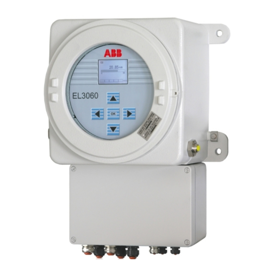
- Page 1 EasyLine Continuous Gas Analyzers EL3060 Series Gas Analyzers for Use in Hazardous Locations Instructions for Installation, 41/24-406 EN Rev. 3 Start-up and Operation...
-
Page 3: Table Of Contents
Contents Contents Preface ..............................4 Guideline for Installation and Commissioning ...................6 Safety Information..........................7 Intended Use .....................7 Safety Instructions..................7 Information for the Installation, Maintenance and Repair of Electrical Installations in Hazardous Areas..........10 Description of the Gas Analyzers ......................12 Preparation for Installation.........................15 Scope of Supply and Delivery ..............15 Material Required for the Installation (not supplied) ........16 Requirements at the Installation Site, Power Supply.......17 Sample gas inlet conditions under atmospheric conditions .....19... -
Page 4: Preface
Information on spare parts can be found on the CD-ROM "Spare parts analytical", which is enclosed with the gas analyzer. Internet You will find information on ABB Analytical products and services on the Internet at "http://www.abb.com/analytical". Service contact If the information in this operator's manual does not cover a particular situation, ABB Service will be pleased to supply additional information as required. - Page 5 Preface Symbols and Typefaces in the Operator's Manual ATTENTION identifies safety information to be heeded during gas analyzer operation, in order to avoid risks to the user. NOTE identifies specific information on the operation of the gas analyzer as well as on the use of this manual. 1, 2, 3, ...
-
Page 6: Guideline For Installation And Commissioning
EasyLine EL3060 Series Commissioning Instructions Guideline for Installation and Commissioning Basic Steps The following basic steps should be followed for the installation and commissioning of the gas analyzer: Note the information on the intended application (see page 7). Follow the safety information (see page 7). -
Page 7: Safety Information
Safety Information Safety Information Intended Use Intended Application of the Gas Analyzer The gas analyzers of the EL3060 series are intended for the continuous quantitative determination of individual gas components in gas mixtures. Any other application is not compliant with the specified use. The specified use also includes taking note of this operator's manual. - Page 8 EasyLine EL3060 Series Commissioning Instructions Instructions and Regulations to be observed These include · The contents of this operator's manual, · The safety information affixed to the device, · The applicable safety regulations for installing and operating electrical devices, ·...
- Page 9 Safety Information Risks Involved when Opening the Covers Current-bearing components can be exposed when the covers or parts are removed, even if this can be done without tools. Current can be present at some connection points. Risks Involved in Working with an Open Device Before carrying out any work on an open instrument, all poles must be disconnected from all power sources.
-
Page 10: Information For The Installation, Maintenance And Repair Of Electrical Installations In Hazardous Areas
EasyLine EL3060 Series Commissioning Instructions Information for the Installation, Maintenance and Repair of Electrical Installations in Hazardous Areas Installation to IEC/EN 60079-14 (VDE 0165 Part 1) The electrical apparatus must be installed according to IEC/EN 60079-14 (VDE 0165 Part 1) "Electric Apparatuses for Potentially Explosive Gas Atmospheres"... - Page 11 Repair by the Manufacturer The repair can also be carried out by the manufacturer, e.g. locally by an employee of the ABB after sales service or at the manufacturer's works. In this respect, an indication of the repairs carried out with a subsequent individual test is affixed to the type plate.
-
Page 12: Description Of The Gas Analyzers
EasyLine EL3060 Series Commissioning Instructions Description of the Gas Analyzers Versions of the Gas Analyzers EL3060-CU Control unit with no analyzer installed (with power supply for a separate analyzer unit) EL3060-Caldos25 EL3060-CU with Caldos25 analyzer installed EL3060-Caldos27 EL3060-CU with Caldos27 analyzer installed... - Page 13 Description of the Gas Analyzers Case Purging In order to protect the electronic assemblies from an ingressing aggressive atmosphere or corrosive sample gas components, the flameproof case can be purged with air or inert gas. The purge gas is fed in and conducted away via two flame barriers, which are open on the inside of the flameproof case.
- Page 14 EasyLine EL3060 Series Commissioning Instructions Electrical Safety Test to EN 61010-1:2001 / IEC 61010 Class of protection Overvoltage category Power supply, signal inputs and outputs: III Degree of pollution Safe isolation Electrical isolation of the power supply from the other circuits through increased or double insulation.
-
Page 15: Preparation For Installation
Preparation for Installation Preparation for Installation Scope of Supply and Delivery Scope of Supply and Delivery · Gas Analyzer Model EL3060 · Accessories pack with: · CD-ROM "Software Tools and Technical Documentation" · CD-ROM "Spare Parts Analytical" · Instructions for Installation, Commissioning and Operation ·... -
Page 16: Material Required For The Installation (Not Supplied)
EasyLine EL3060 Series Commissioning Instructions Material Required for the Installation (not supplied) Gas Connections · Threaded connections with 1/8 NPT threads · PTFE sealing tape Flow Meter / Flow Monitor · Flow meter or flow monitor with a needle valve for adjustment and... -
Page 17: Requirements At The Installation Site, Power Supply
Preparation for Installation Requirements at the Installation Site, Power Supply Installation site The gas analyzer is only intended for installation indoors; it may not be installed outdoors. The installation site must be stable enough to bear the weight of the gas analyzer! Short gas paths Install the gas analyzer as close as possible to the sampling location. - Page 18 EasyLine EL3060 Series Commissioning Instructions Power supply Input voltage 100…240 V AC, 50…60 Hz ± 3 Hz Power consumption Max. 187 VA Battery Lithium 3 V CR2032 button cell, to supply the integrated clock during a power failure NOTE The IECEx-certified instrument is supplied without a battery installed; a...
-
Page 19: Sample Gas Inlet Conditions Under Atmospheric Conditions
Preparation for Installation Sample gas inlet conditions under atmospheric conditions Sample gas composition The standard version of the gas analyzer is suitable for measuring non- flammable and flammable gases under atmospheric conditions, which can occasionally form a potentially explosive atmosphere. The oxygen content of the sample gas mixture may be max. -
Page 20: Sample Gas Inlet Conditions With Positive Pressure In The Sample Gas Feed Path
EasyLine EL3060 Series Commissioning Instructions Sample gas inlet conditions with positive pressure in the sample gas feed path Sample gas composition A special version of the gas analyzer is suitable for measuring non- flammable and flammable gases under positive pressure. Under no circumstances may the sample gas be potentially explosive. - Page 21 Preparation for Installation Sample gas inlet and outlet conditions for Magnos206, Caldos25, Caldos27 analyzers Temperature +5…+50 °C Inlet and outlet pressure The sample gas pressure in the sample gas feed path of the analyzer may be max. 200 hPa (1200 hPa absolute). The pressure drop at the flame barrier at the sample gas inlet means this can be achieved by ·...
-
Page 22: Test Gases For The Calibration
EasyLine EL3060 Series Commissioning Instructions Test Gases for the Calibration Uras26 Version Test gas for the zero Test gas for the end-point calibration calibration Uras26 with calibration cells or air or IR sample – (calibration cells) (automatic calibration) component-free gas... - Page 23 Preparation for Installation Magnos206 Version Test gas for the zero Test gas for the end-point calibration calibration Magnos206 Oxygen-free process gas Process gas with a known O concentration Magnos206 with a suppressed Test gas with O concentration Test gas with O concentration measuring range near the starting point of the...
-
Page 24: Pressure Sensor
EasyLine EL3060 Series Commissioning Instructions Pressure Sensor Uras26 The pressure sensor is installed in the gas analyzer as standard. It is optionally connected to a gas port via an FPM tube (flame barrier). Magnos206 The pressure sensor is optionally installed in the gas analyzer. It is optionally connected to a gas port via an FPM tube (flame barrier). -
Page 25: Case Purging
Preparation for Installation Case Purging The cases of the control unit and the analyzer unit Uras26 can be purged as an option for protection of the gas analyzers in a corrosive environment or with corrosive sample or associated gases. Purge Gas Clean instrument air from non-hazardous areas or inert gas is to be used as a purge gas. -
Page 26: Dimension Drawing And Gas Connections Of The El3060-Cu Control Unit
EasyLine EL3060 Series Commissioning Instructions Dimension Drawing and Gas Connections of the EL3060-CU Control Unit EL3060-CU control unit (dimensions in mm) 199.5 92.5 45.5 124.5 60.5... - Page 27 Preparation for Installation Standard version: Version for measuring gases under positive pressure: Sample gas inlet Vent Sample gas outlet Sample gas outlet Purge gas inlet Purge gas inlet Purge gas outlet Sample gas inlet 3, 4) Connection of the pressure Connection of the pressure sensor sensor or purge gas outlet...
-
Page 28: Dimension Drawing And Gas Connections Of The Analyzer Unit
EasyLine EL3060 Series Commissioning Instructions Dimension Drawing and Gas Connections of the Analyzer Unit EL3060-Uras26 Analyzer Unit (Dimensions in mm) - Page 29 Preparation for Installation ) Assignment of the ) gas connections ) see ) analyzer data sheet (see page 32) Purge gas inlet Purge gas outlet Connection of the pressure sensor Conduit for data transmission cable Conduit for 24 VDC connecting cable Connection for equipotential bonding Option The connection of the pressure sensor (see page 24) must not be...
-
Page 30: Installing The Gas Analyzer
EasyLine EL3060 Series Commissioning Instructions Installing the Gas Analyzer Unpacking the Gas Analyzer ATTENTION The EL3060-CU control unit weighs approx. 20 kg. The EL3060- Uras26 analyzer unit weighs approx. 25 kg. Unpacking and installing of the gas analyzer require two persons! -
Page 31: Type Plate
Installing the Gas Analyzer Type Plate Contents of the Type Plate The type plate contains the following information: · Production number (F-No.) · Order number (A-No.) · Power supply (voltage, frequency, max. power consumption) · Installed analyzers with sample components and measuring ranges... -
Page 32: Analyzer Data Sheet
EasyLine EL3060 Series Commissioning Instructions Analyzer Data Sheet Contents of the Analyzer Data Sheet The analyzer data sheet is in the accessories pack. It contains the following information: · Order number (A-No.) · Part number (P-No.) · Production number (F-No.) ·... -
Page 33: Checking The Seal Integrity Of The Gas Feed Paths
Installing the Gas Analyzer Checking the Seal Integrity of the Gas Feed Paths Checking the Seal Integrity of the Gas Feed Paths The seal integrity of the sample gas feed path and, if applicable, of the reference gas feed path is checked ex works with a helium leak test for a –4 leakage rate of <... -
Page 34: Installing The Gas Analyzer
EasyLine EL3060 Series Commissioning Instructions Installing the Gas Analyzer ATTENTION The EL3060-CU control unit weighs approx. 20 kg. The EL3060- Uras26 analyzer unit weighs approx. 25 kg. Unpacking and installing of the gas analyzer require two persons! Mounting the EL3060-CU Control Unit 4 bolts M8 or M10 are required to mount the EL3060-CU control unit (not supplied). -
Page 35: Connecting The Gas Lines
Installing the Gas Analyzer Connecting the Gas Lines Position and Layout of the Gas Connections The position and layout of the gas connections are shown in the dimension drawings of the control unit (see page 26) and the analyzer unit (see page 28). Design of the Gas Connections Design of the gas connections: Internal flame barriers of rust- and acid- resistant steel 1.4571 with 1/8 NPT female thread... - Page 36 EasyLine EL3060 Series Commissioning Instructions Connecting the Gas Lines Connect the stainless steel pipes to the fittings (flame barriers) professionally and taking tightness requirements into consideration. ATTENTION The maximum permissible tightening torque is 50 Nm. If this value is exceeded, the internal gas connections could be damaged. The explosion protection could be impaired as a result.
-
Page 37: Connecting The Electrical Leads - Safety Information
Installing the Gas Analyzer Connecting the Electrical Leads - Safety Information ATTENTION Follow all applicable national safety regulations for the installation and operation of the electrical apparatuses as well as the following safety instructions Equipotential Bonding The external equipotential bonding connections of the control unit and the analyzer unit must be connected to the local potential equalization. -
Page 38: Electrical Connections
EasyLine EL3060 Series Commissioning Instructions Electrical Connections NOTE Not all signal input and outputs are actually assigned, depending on the configuration of the gas analyzer. Digital Inputs Opto-electronic coupler with 24 V DC internal power supply. Activation with floating contacts or with Open-Collector drivers NPN. - Page 39 Installing the Gas Analyzer Standard Assignment of the Digital Inputs and Digital Outputs Signal Standard Assignment Standard Assignment Digital I/O Module 1 Digital I/O Module 2 Failure Maintenance request Maintenance mode Overall status Start automatic calibration Stop automatic calibration Disable automatic calibration Sample gas valve Zero-reference gas valve Span reference gas valve...
- Page 40 EasyLine EL3060 Series Commissioning Instructions Analog Outputs 0/4…20 mA (pre-set ex works to 4…20 mA), common negative pole, electrically isolated to ground, can be connected to ground as required, in this regard, max. gain compared to local protective ground potential 50 V, working resistance max.
- Page 41 Installing the Gas Analyzer Assignment of the Connecting Cables to the Cable Connectors Connecting Cable Screwed Cable Gland Permissible External Diameter of Cable Gas analyzer power supply Plastic M16 4…8 mm Power supply to EL3060-Uras26 Metal M20 7…12 mm Data transfer for EL3060-Uras26 Metal M20 7…12 mm Ethernet...
-
Page 42: Connect The Electrical Leads
EasyLine EL3060 Series Commissioning Instructions Connect the Electrical Leads Pass Cable through a Metal Screwed Cable Gland of the Control Unit Bare the braided shield of the cable over a length of approx. 10 mm. Undo the coupling nut on the metal screwed cable gland and remove the terminal insert. -
Page 43: Starting Up The Gas Analyzer
Starting Up the Gas Analyzer Starting Up the Gas Analyzer Check the Installation NOTE The case of the gas analyzer can also be opened in the presence of an explosive atmosphere if all electrical lines have been disconnected from the supply and 10 minutes have passed since disconnection. Check the Installation Before you put the gas analyzer into operation, you should ensure that it has been correctly installed. - Page 44 EasyLine EL3060 Series Commissioning Instructions · Do the 24 VDC connecting cable and the data transmission cable which are securely connected to the EL3060-Uras26 analyzer unit have a length of more than 1 m and do they have any damage? Integrity of the Case of the EL3060-Uras26 Analyzer Unit ·...
-
Page 45: Initial Purging Of Gas Feed Paths
Starting Up the Gas Analyzer Initial Purging of Gas Feed Paths Initial Purging of Gas Feed Paths Initial purging of the gas feed paths is required for the initial start-up and each time the gas feed paths inside the gas analyzer have been opened before the power supply is switched on. -
Page 46: Start Up The Gas Analyzer
EasyLine EL3060 Series Commissioning Instructions Start up the Gas Analyzer Start up the Gas Analyzer Switch on the power supply of the gas analyzer The name of the gas analyzer and the number of the software version are shown in the display while booting. -
Page 47: Operating The Gas Analyzer
Operating the Gas Analyzer Operating the Gas Analyzer NOTE All the illustrations of the displays in this operator's manual are examples. The displays on the instrument will normally differ from these. Display - Measuring Mode Display in Measuring Mode In measuring mode, the screen displays the name, the measured value in numerals and the physical unit of the measured value for each sample component. - Page 48 EasyLine EL3060 Series Commissioning Instructions Status Icons An automatic calibration is executed. The icon also appears in the menu title line in menu mode (see page 50). A status message is active. The status signal "Maintenance request" is active. The icon also appears in the menu title line in menu mode (see page 50).
- Page 49 Operating the Gas Analyzer Number of Decimal Places When the screen displays the measured value in physical units (e.g. ppm) the number of places after the decimal point depends on the size of the set measuring range: Span Places after the decimal point £...
-
Page 50: Operation - Menu Mode
EasyLine EL3060 Series Commissioning Instructions Operation - Menu Mode Display in Menu Mode Structure of the Menus Starting from the main menu, each menu (see page 53) contains a maximum of three menu items ("3-point menu"). Each menu option is assigned to one of the three keys , and ;... - Page 51 Operating the Gas Analyzer Key Functions in Menu Mode 3-point menu Select menu item Return to the next higher menu Return to measuring mode (see page 47) Component list Select component or OK Call up selected component for processing Parameter list ("Selector") Select parameters Call up change in value Accept all displayed values and...
- Page 52 EasyLine EL3060 Series Commissioning Instructions Time-out Function If the user does not press a key for more than approx. 5 minutes during the selection of menu items, the gas analyzer will automatically return to the measuring mode (see page 47) (time-out function).
-
Page 53: Menu
Operating the Gas Analyzer Menu Overview of the Menu * This menu depends on the configuration of the gas analyzer. -
Page 54: Information On The Concept Of Operation
EasyLine EL3060 Series Commissioning Instructions Information on the Concept of Operation Concept of Operation The concept of operation of the gas analyzers is designed in such a way that the functions required in normal operation are operated and configured directly on the instrument. On the other hand, the functions which are only seldom required, e.g. - Page 55 Operating the Gas Analyzer Overview of the functions Function Instrument Configurator Modbus Automatic calibration: Start/cancel automatic calibration (also possible via digital inputs) Activate/deactivate cyclically time-controlled automatic calibration Cycle time of the automatic calibration End-point calibration together with zero-point calibration Date and time of the next automatic calibration (start of the cycle) Test gas concentration Purging times...
-
Page 56: Communication Between The Gas Analyzer And The Computer
EasyLine EL3060 Series Commissioning Instructions Communication between the Gas Analyzer and the Computer Communication via Ethernet Communication between the gas analyzer and the computer is executed via an Ethernet connection, either as a point-to-point connection or via a network. The Ethernet connection enables communication ·... - Page 57 Operating the Gas Analyzer Set the IP address in the gas analyzer Setup Device settings Ethernet Parameters The parameters which have to be input depend on the DHCP setting: DHCP on: Network name (max. 20 characters, no blanks or special characters), DHCP off: IP address, IP address mask and IP gateway address.
- Page 58 EasyLine EL3060 Series Commissioning Instructions Set the IP address in the computer Start – Settings – Network connections, right click on "Local Area Connection" – Properties – Tab "General": Select Internet Protocol (TCP/IP), Properties – Tab "General": Use the following IP address: –...
- Page 59 Operating the Gas Analyzer Start the communication between the gas analyzer and the computer Communication between the configurator and the gas analyzer is started in the menu "Options – Communication Properties…" or by clicking the symbol . Input either the IP address or the network name (server name) of the gas analyzer (see the following example of a point-to-point connection).
-
Page 60: Maintenance
EasyLine EL3060 Series Commissioning Instructions Maintenance Inspection Regular Inspection Proceed in accordance with the checklist "Checking the installation" (see page 43). Checking the Seal Integrity of the Gas Feed Paths The seal integrity of the sample gas feed path and, if applicable, the ref- erence gas feed path should be checked during operation at least once a year. - Page 61 Maintenance Reseal Cable Glands after Opening If the pressure-proof cable glands, through which the data transmission cable and the 24 VDC connecting cable are routed to the flameproof cylinder of the EL3060-Uras26 analyzer unit, have been opened, the external nuts must be screwed tight with a torque wrench (size 20); tightening torque = 17 Nm.
-
Page 62: Checking The Seal Integrity Of The Gas Feed Paths
EasyLine EL3060 Series Commissioning Instructions Checking the Seal Integrity of the Gas Feed Paths Requisite Material · Pressure gauge · Flexible tubing, length approx. 1 m · T-piece with shut-off valve · Air or nitrogen ATTENTION If the seal integrity test is to be carried out with air and if flammable gas... -
Page 63: Shutting Down And Packing The Gas Analyzer
Shutting Down and Packing the Gas Analyzer Shutting Down and Packing the Gas Analyzer Shutting Down the Gas Analyzer Shutting Down the Gas Analyzer In the case of a temporary shutdown: Shut off the sample gas. Purge the gas lines and gas feed paths in the analyzer module with dry fresh air or nitrogen for at least 5 minutes. -
Page 64: Packing The Gas Analyzer
EasyLine EL3060 Series Commissioning Instructions Packing the Gas Analyzer Packing Remove adapters from the the gas ports and tightly seal the gas ports. If the original packaging is not available, wrap the gas analyzer in bubble wrap or corrugated cardboard. When shipping overseas, additionally shrink-wrap the gas analyzer air-tight in 0.2 mm thick... -
Page 65: Index
Index Information on the Concept of Operation • 40, Index 54, 57 Initial Purging of Gas Feed Paths • 6, 45 Inspection • 60 Installation Required Material • 16 Analog outputs • 38 Installation site • 17 Analyzer Data Sheet • 15, 29, 32 Installing the Gas Analyzer •... - Page 66 EasyLine EL3060 Series Commissioning Instructions Test Gases for the Calibration • 22 Time-out function • 50 Type Plate • 31 Unpacking • 30 Unpacking the Gas Analyzer • 6, 30 Warm-up phase • 46 Waste gases • 35...
- Page 68 ABB has Sales & Customer Support expertise The Company’s policy is one of continuous product in over 100 countries worldwide. improvement and the right is reserved to modify the information contained herein without notice. www.abb.com Printed in the Fed. Rep. of Germany (08.13) ã...