
Related Manuals for Extech Instruments RHT30


Summary of Contents for Extech Instruments RHT30
- Page 1 USER MANUAL USB Multi‐Function Dataloggers RHT30 Humidity/Temperature Datalogger TH30 Dual Temperature Datalogger 888.610.7664 www.calcert.com sales@calcert.co...
- Page 2 Introduction Thank you for selecting the Extech multi‐function, easy‐to‐use, portable USB datalogger. The RHT30 offers temperature and humidity logging and the TH30 offers internal (air) and external (probe) temperature logging. These USB dataloggers can be configured and customized by the user by plugging them into a PC USB port, following the on‐screen prompts, and making selections on the supplied ‘PDF Logger Configuration Tool’. These devices are shipped fully tested and calibrated and, with proper use, will provide years of reliable service. Features Plug‐and‐play datalogger with USB connector. No USB driver required User configurable datalogging settings via supplied PC software tool Advanced Datalogger functions including delayed start, high/low alarms, bookmarking, and password protection Automatically generate PDF and Microsoft ® ® Excel datalog reports High accuracy thermistor temperature sensor on both models with capacitive humidity sensor on the RHT30 Compact light‐weight design Large LCD for easy viewing Dual color (red and green) LED status indicator for datalogger progress, PC connection status, and high/low alarms Large memory capacity: 48,000 readings Descriptions Datalogger Description 1.
-
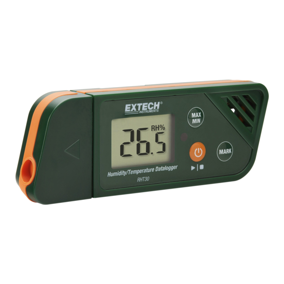
Page 3: Button Descriptions
5. Status LED indicator (red/green). Refer to the Status LED Indicator Description later in this section. 6. MAX‐MIN button. Refer to the Button Descriptions later in this section. 7. Sensors (Thermistor internal air temperature and capacitive RH sensor) 8. Power and Datalog Start/Stop button. Refer to the Button Descriptions later in this section. 9. MARK/Battery life button. Refer to the Button Descriptions later in this section. 10. USB plug 11. Battery compartment (CR2032 x 2) on rear 12. Wall hanging mount (rear). Mounting screw supplied. Button Descriptions POWER button. Short press to power ON or OFF. Note that the datalogger cannot be switched OFF while datalogging is in progress. START/STOP button (same physical button as the Power button above). Press and hold for 5 seconds to start or stop the datalogger. Note that the datalogger will not start unless it has been configured using the ‘PDF Logger Configuration Tool.exe’ program as described later in this user manual. Maximum‐Minimum Reading button. At any time, short press to step through the highest (MX) and lowest (MIN) readings recorded in the current datalogging session. Bookmark button. Manually place a time‐stamped ‘bookmark’ in the datalog report by pressing and holding the button until the displayed measurement flashes 3 times. Up to eight (8) bookmarks can be saved. Battery Status Note: Short press the MARK button to display the approximate number ... -
Page 4: Led Status Indicator Description
Display (LCD) Description F Temperature unit of measure as programmed by the user Displayed when showing Relative Humidity reading (RHT30) Represents the internal sensor (air) temperature (TH30) R epresents the external probe temperature. If no probe is connected, the display will show dashes for the T2 temperature reading (TH30) High Alarm triggered Low Alarm triggered R EC flashes once per second when actively datalogging. When logger is programmed with a ‘Start Delay’, REC is displayed but does not flash until after the delay time has elapsed and the logging begins B attery icon flashes once per second when battery level is critically low D isplayed when the maximum recorded reading is selected with the MAX‐MIN button ... - Page 5 PDF Logger Configuration Tool Connect the datalogger to PC USB port. The PC will prompt to view files. Open the ‘PDF Logger Configuration Tool’ from the list of available files. Refer to the Operation Section for additional details on this tool: 2 3 4 5 15 6 14 7 13 8 9 10 1. CONVERT TO EXCEL: Create a spreadsheet report of the logged data 2. CONVERT TO PDF: Create a PDF report and a trend graph of the logged data 3. CONFIGURATION: Click to configure the logger 4. LANGUAGE SELECTION 5. SAMPLING RATE: Datalogger recording interval 6. START DELAY: Delay period from when START is pressed and datalogging begins 7. TEMP. UNIT: Temperature unit selection ( F) 8. PASSWORD: Select a 16‐character password for tamper protection 9. COMPANY NAME: 20‐Character user label for inclusion in logging report 10. SAVE: Press SAVE to confirm the configuration 11.
-
Page 6: Operation
Operation NOTES: 1. Adobe Reader® software is required. 2. Ensure the logger is at room temperature before inserting it into a PC port. 3. The executable file for programming is named “PDF Logger Configuration Tool”. 4. A datalogging session cannot start until the datalogger is properly configured. Configuring the TH30 and RHT30 for a Datalogging session At any time before logging is started, the logger can be programmed and re‐ programmed. The previous logging session will be deleted once a new session is started. 1. Connect the data logger to a PC via the USB port. The logger will switch ON automatically. Note that a short press of the power button will also power the logger. 2. The LED will glow green while a connection with computer is being established. 3. An AutoPlay prompt will appear on the PC when communication is established. 4. Click on ‘Open folder to view files’ to see the available files. Open the program "PDF Logger Configuration Tool.exe". 5. The default language is English; select German, French, Italian, Spanish, or Portuguese as desired. The generated logging report format will match the language selected. 6. To review the User Manual, click ‘Manual’ to open the User Manual PDF file. 7. The parameters needed to configure the datalogger for logging are defined below. Refer to the earlier screen shot of the ‘PDF Logger Configuration Tool’ window for reference: Datalog Sampling Rate Select the datalogging sampling rate (recording interval) from 30 seconds ~ 120 minutes. The default setting is 30 seconds. ... - Page 7 Alarm Delay The preset alarm delay time for the Single Event Alarm mode is always zero. The adjustable delay time range for the Cumulative Alarm is 5 ~ 120 minutes. Alarm Modes Single Event Alarm mode: The LED immediately starts flashing red every 10 seconds when the measured value exceeds the alarm threshold. Cumulative Alarm mode: The LED begins flashing red only after the average value exceeds the alarm threshold and also after any programmed Alarm Delay time. See Alarm Delay parameter above. Alarm Disable (default): Alarm function disabled. Alarm Note: The LED will continue flashing red every 10 seconds (once it is triggered by an alarm) even when the measurement later returns to the normal range. To stop the LED alarm, plug the logger into the PC USB port to generate a report, or power off the logger (short press of the power button while it is not connected to the PC). Alarm Limits Select the alarm threshold ranges for air and external probe temperature (TH30) or air temperature and RH% (RHT30). For example, if the external o probe temperature range is set to 2.0~8.0 C, when the measurement falls o below 2 C or exceeds 8 C the LED will flash red every 10 seconds. Note: If an alarm occurs between two logging points, the logged data will not show the alarm but the LED may still flash red every 10 seconds, especially in Single Event alarm mode. If desired, use the Cumulative Alarm mode to minimize this effect. Password A 16 alphanumeric character (max.) password may be used to prevent unauthorized re‐programming. User Company Name Input a company name to be included on the log report (20 characters max.). A Note On Time Zones ...
-
Page 8: Start Datalogging
Start Datalogging 1. Configure the logger as previously described and then hold the Start/Stop button for 5 seconds to start logging. 2. Measurements update on the display every 10 seconds. For the RHT30 the temperature and RH% displays toggle every 5 seconds. 3. If the logger is programmed with a Start Delay: After pressing and holding the Start/Stop button for 5 seconds to start logging, REC will appear on the LCD but will not flash until the delay time has elapsed and logging has begun. 4. When the datalogger is successfully running, the LED flashes green every 10 seconds (as long as there is no alarm). Monitoring Alarms While Datalogging The LED will flash RED every 10 seconds when there is an alarm. The display also shows ‘L’ for low alarm and ‘H’ for high alarm. To stop the LED from flashing red, plug the logger into a PC, or power off (short press of the power button). Placing ‘Bookmarks’ While Datalogging To place a bookmark manually during datalogging, press and hold the MARK button until the measured reading flashes 3 times. Up to eight (8) bookmarks can be placed; the bookmarks will appear in the logging report. MAX‐MIN Readings Short press the MAX‐MIN button to step through the highest (MX) and lowest (MN) readings stored in memory. Checking Battery Status At any time, short press the MARK button to view the approximate number of days remaining for battery life. If battery power is critically low, the battery icon will blink once per second on the LCD display. Downloading Logged Data (PDF and Spreadsheet Datalog Reports) 1. Press and hold the Start/Stop button for 5 seconds to stop the datalogger. 2. Plug the logger into the PC USB port (this also stops the datalogger). 3. Open the ‘PDF logger Configuration tool’ from the list of available files. 4. Choose ‘Convert to PDF’ or ‘Convert to Excel’ to generate a report. ... -
Page 9: Specifications
Specifications Display (LCD) 5‐digit LCD with multi‐function indicators Status indicator (LED) Dual color multi‐purpose LED (red/green) for active logging, alarms, and PC connection status Temperature Sensors NTC Thermistors (TH30/RHT30 internal temperature sensors and TH30 external temp. probe) Ext. Temperature probe length 2.1m (84”) (TH30) Temperature range ‐30 ~ 70 C (‐22 ~ 158 F) internal and external probes Temperature resolution F Temperature Accuracy ±0.5 C (0.9 F) for internal and external (TH30) probe Humidity Sensor Capacitive (Relative Humidity) RHT30 only Humidity range 0.1 ~ 99.9%RH Humidity resolution 0.1%RH Humidity Accuracy ±3% at 25 C (10 ~ 90%RH), ±5% all other ranges ... -
Page 10: Maintenance
life devices to a designated collection point for the disposal of electrical and electronic equipment. Battery Status Check To check the approximate number of days of battery life remaining, short press the MARK button. The display will show the number of days and the ‘d’ for days (XXd). Cleaning Wipe the datalogger with a damp cloth, do not use solvents or abrasives as these may damage the datalogger finish and display lens. Error Display Codes ERROR CAUSE SOLUTION Dashes External probe unplugged (TH30 only) Check the connection between the external probe and logger ‐ ‐ ‐ ‐ ‐ . ‐ E02 Measured value below specified range Operate in the specified range E03 Measured value above specified range Operate in the specified range E04 Temperature error (RHT30 only) Contact Extech for service E11 Humidity check failed (RHT30 only) Contact Extech for service E31 Microprocessor failed Contact Extech for service E33 Humidity measurement error Contact Extech for service RHT30_TH30‐en‐GB_V1.0 (11/16) 888.610.7664 www.calcert.com sales@calcert.co...
Need help?
Do you have a question about the RHT30 and is the answer not in the manual?
Questions and answers