Yamaha 02R Owner's Manual
Digital recording console
Hide thumbs
Also See for 02R:
- Application manual (89 pages) ,
- Manual (398 pages) ,
- Installation manual (14 pages)
Chapters
Table of Contents

Related Manuals for Yamaha 02R


Summary of Contents for Yamaha 02R
- Page 1 DIGITAL RECORDING CONSOLE...
- Page 2 1. IMPORTANT NOTICE: DO NOT MODIFY THIS UNIT! This product, when installed as indicated in the instructions contained in this manual, meets FCC requirements. Modifications not expressly approved by Yamaha may void your authority, granted by the FCC, to use the product.
-
Page 3: Important Information
Do not place the 02R in a narrow, non-ventilated space, such as in a bookcase or closet. Use a dedicated rack. • Do not place a table cloth on top of the 02R; do not place the 02R on a carpet or mattress. •... - Page 4 Otherwise, an extremely loud noise could damage your hearing. • If you plan not to use the 02R for a long period of time (such as when you are on vacation), remove the power plug from the AC outlet. Otherwise, a fire could possibly result.
- Page 5 02R under this condition, fire or electrical shock may result. • If the 02R is dropped, or the cabinet is damaged, turn off the power switch, remove the power plug from the AC outlet, and consult your dealer. If you continue using the 02R under this condition, fire or electrical shock may result.
- Page 6 Digital Recording Console 02R Owner’s Manual Influences on other electrical devices This equipment uses many digital circuits, which may cause noise to occur on nearby radio or TV. In this case, relocate the 02R away from those devices. Exclusion of Certain Damages...
- Page 7 DIGITAL RECORDING CONSOLE User’s Guide...
-
Page 8: Table Of Contents
Introduction to the 02R..... . 1 Digital Recording Console 02R ......2 User Guides . - Page 9 Mixing and Automation ....67 What is 02R Automation? ....... . 68 Real-Time Automation .
-
Page 10: Introduction To The 02R
Digital Recording Console 02R ........ -
Page 11: Digital Recording Console 02R
I/O cards, you can also have 8 channels of direct digital input. Depending on configuration, up to four cards can be inserted into the 02R. The cards allow you to select from any of the currently used formats (ADAT®, TDIF™, YAMAHA, or AES/EBU). The optional cards allow you to route up to 16 outputs directly to your modular digital multitrack recorder. -
Page 12: User Guides
You should keep this manual handy for future reference. Getting Started Guide The Getting Started Guide sections contain a simple description and a couple of tutorials about digital recording with the 02R to get you started. It also has a tutorial on the automation system. User’s Guide The User’s Guide sections explain each 02R function in full detail. -
Page 13: Top And Rear Panels
+4dB MONITOR MONITOR STEREO OUT ANALOG ANALOG +4dB +4dB POWER ON/ OFF METER SMPTE TIME CODE INPUT Digital Recording Console 02R Getting Started Guide Top and Rear Panels +48V +48V +48V 20dB 20dB 20dB 20dB 20dB 20dB 20dB 20dB 20dB... -
Page 14: Features
• 105 dB dynamic range (typical) • 32-bit precision internal processing with a dynamic range of over 190 dB using YAMAHA’s 32-bit proprietary audio DSP General Features • 40 input channel mixer, with full dynamic processing and 4-band parametric equalization •... - Page 15 Digital Recording Console 02R Getting Started Guide • 2 analog stereo outputs • 6 analog auxiliary send outputs • Stereo studio and control room outputs • 3 digital 2TR IN inputs • 2 digital stereo outputs • Industry standard AES/EBU or IEC958 Part2 (Consumer) digital inputs and outputs •...
-
Page 16: Key Features
Scene Memories The 02R has 64 internal scene memories each of which is a snapshot of all the digital settings of the mixer (a mix scene). Each can be named for easy identification. - Page 17 See “Fade Time” on page 121 of the User’s Guide. Large Graphical Display The heart of the 02R user interface is the large graphical display located in the center of the console. Using the Display Access controls, you can gain immediate access to the features of the mixer –...
- Page 18 Effect1 and Effect2. Using the power of YAMAHA’s proprietary effects processor chip, the 02R has a startling range of special effects available to apply to your mix. Shimmering reverbs, clean and precise delays, flanging and chorus, and a myriad of other effects are available built right into this mixer.
- Page 19 In the digital realm, audio mixing consists of adding and multiplying the binary numbers that represent audio signals. The 02R uses a 32-bit DSP (Digital Signal Processor) chip for these calculations, ensuring a very high degree of precision.
- Page 20 105 dB. This means that an audio program’s dynamic range, from low to high levels, is processed intact. The 02R samples audio at 44.1kHz, the commercial sampling rate for compact discs, and at 48kHz, the professional sampling rate.
- Page 21 Introduction to the 02R Digital Recording Console 02R Getting Started Guide...
-
Page 22: Getting Started
Recall Scene Memory 0 ......... . 17 Digital Recording Console 02R Getting Started Guide... -
Page 23: Basic Assumptions
Digital Recording Console 02R Getting Started Guide Basic Assumptions The Digital Recording Console 02R was designed to be the perfect digital mixing console for a studio using the current generation of modular digital multitrack tape and disk recorders. Although the 02R can also be... -
Page 24: Basic Setup
Getting Started Basic Setup The following illustration shows how to set up a minimal system that will allow you to perform the following tutorials. Amplifier Sound Source Multi-track recorder Digital Recording Console 02R Getting Started Guide... -
Page 25: Power On/Off
Look in the chapter “Installing Options” on page 171 of the User’s Guide. There is a section for each of the optional digital I/O cards that the 02R supports. Refer to the appropriate section for the card installed in your... -
Page 26: Recall Scene Memory 0
Getting Started Recall Scene Memory 0 Before you start the tutorials, you should set the 02R to its initial mixer settings. 2. Use the SCENE MEMORY increment or decrement buttons to select scene memory 0 “0 Initial Data”. 3. Press the [RECALL] button. - Page 27 Getting Started Digital Recording Console 02R Getting Started Guide...
-
Page 28: Introductory Recording Tutorial
Panning ............38 Digital Recording Console 02R Getting Started Guide... -
Page 29: Setting The Input Level
Note: Be very careful with the level settings, especially if you are using stereo headphones. When you are adjusting a unit as complex as the Digital Recording Console 02R, it is possible for you to inadvertently switch on a very loud signal source. Damaged loudspeakers or amplifiers can be very expensive. Damage to... -
Page 30: Setting The Gain
If you want to use a very high impedance device, such as a guitar or bass guitar, you should insert a direct box or effects processor between the guitar and the 02R – or you should mike the guitar amplifier. Note: The stereo input channels (LINE 17 through 24) accept line level signals only. -
Page 31: Peak Hold
/ATT display function, press the [METER] button again. The 02R will return to the METER display function. 2. You may find the Peak Hold function useful at this point. To turn it on, use the CURSOR buttons to select the PEAK HOLD control icon and press [ENTER]. - Page 32 MEMORY program. It also contains the Edit Indicator, which will start flashing when you adjust the first digital parameter of the current scene memory. See “Scene Memories” on page 62 of the Getting Started Guide. Edit Indicator Digital Recording Console 02R Getting Started Guide...
-
Page 33: Applying Eq
HIGH/LPF EQ ON EQUALIZER Note: You can customize your 02R so that when you adjust a control of the EQUALIZER block of the SELECTED CHANNEL controls, the EQUALIZER display function automatically appears on the screen. See “Preferences” on page 162 of the User’s Guide for more information. The default setting is to automatically display the EQUALIZER screen. - Page 34 [LOW/HPF] button of the SELECTED CHANNEL – EQUALIZER controls. 2. Rotate the encoder wheel clockwise to boost the gain. You can also adjust the “G” rotary encoder of the EQUALIZER controls to achieve the same effect. Digital Recording Console 02R Getting Started Guide...
- Page 35 Digital Recording Console 02R Getting Started Guide The gain increases in 0.5 dB steps and the EQ curve on the display changes to reflect this. 3. Rotate the encoder wheel counterclockwise to reduce the gain. You can also adjust the “G” rotary encoder to reduce the gain. The gain decreases in 0.5 dB steps.
- Page 36 L-MID, H-MID, and HIGH, the frequency of the bands can actually be in any order. Note: If your 02R is busy processing some complex data, it may take a little while to draw the equalization curve. However, the internal EQ circuits reflect your adjustments immediately.
- Page 37 Digital Recording Console 02R Getting Started Guide Setting the Bandwidth The L-MID and H-MID bands are peaking type equalizers. The LOW and HIGH bands are initially configured as shelving type equalizers, however, they can also be configured as peaking type equalizers. The LOW band can also be configured as a HPF (high-pass filter) and the HIGH band as a LPF...
- Page 38 [HIGH/LPF] button of the SELECTED CHANNEL – EQUALIZER controls. All equalizer values will be reset to their defaults. LOW/HPF L-MID LOW SHELF Peak – 0.7 125 Hz 1.00 kHz Digital Recording Console 02R Getting Started Guide H-MID HIGH/LPF Peak – 0.7 HIGH SHELF 4.00 kHz 10.0 kHz...
-
Page 39: Using The Equalizer Library
3. Select the RECALL icon with the CURSOR buttons. In order to scroll through the list of EQ programs, the cursor must be on the STORE, RECALL, COPY, or PASTE icons. Digital Recording Console 02R Getting Started Guide... - Page 40 Introductory Recording Tutorial 4. Use the encoder wheel to select an EQ program. As the 02R scrolls through the list of EQ programs, a small diagram of the response curve of the highlighted EQ program is shown to the right of the list.
- Page 41 Digital Recording Console 02R Getting Started Guide Undoing a Recall If you decided you did not want to replace the current equalization curve with the program you selected from the EQ library, you can recall the previous curve. 1. Use the CURSOR buttons to select the RECALL icon and rotate the encoder wheel until program “U”...
- Page 42 & Move the cursor to the first character position with the CURSOR buttons. Rotate the encoder to select the desired character. Move the cursor to the second character position and repeat. Digital Recording Console 02R Getting Started Guide < >...
- Page 43 6. Use the CURSOR buttons to select the STORE icon and press the [ENTER] button. The 02R will display a popup confirmation request message asking if you want to store your settings in the selected EQ program. The popup has two control icons: “CANCEL”...
-
Page 44: Routing
You can route any channel to one of the eight output buses. The buses feed to each of the four 8-track I/O slots in the back of the 02R. You can also route any channel to the stereo bus. - Page 45 DIRECT ROUTING Note: You can customize the 02R so that when you press a button in the ROUTING block of the SELECTED CHANNEL controls, the ROUTING display function automatically appears on the screen. See “Preferences” on page 162 of the...
- Page 46 The output from that bus will appear at the corresponding outputs of all the I/O cards installed in the 02R. The only exception is when you are using I/O cards in slots 1 and 2 for direct output. See “Routing” on page 39 of the User’s Guide for further details.
-
Page 47: Panning
R/EVEN EVEN Note: You can customize your 02R so that when you adjust a control of the PAN block of the SELECTED CHANNEL controls, the PAN display function automatically appears on the screen. See “Preferences” on page 162 of the User’s Guide for more information. - Page 48 When you adjust one channel, the linked channel will also move by a corresponding amount. For further details, see “Stereo-Pair Pans” on page 37 of the User’s Guide. Digital Recording Console 02R Getting Started Guide...
- Page 49 Introductory Recording Tutorial Digital Recording Console 02R Getting Started Guide...
-
Page 50: Secondary Recording Tutorial
Scene Memories ..........62 Digital Recording Console 02R Getting Started Guide... -
Page 51: Auxiliary Send Channels
Digital Recording Console 02R Getting Started Guide Auxiliary Send Channels The Digital Recording Console 02R has eight auxiliary send channels. AUX7 and AUX8 are used to feed the internal effects processors, with the signal remaining entirely in the digital domain. -
Page 52: Setting The Auxiliary Send Level
Note: Avoid blocking the fader movements when the faders relocate to their auxiliary send positions by placing objects on the 02R. It is possible to damage the faders. Although the faders have moved to the auxiliary send level positions, the 02R remembers the channel signal levels. - Page 53 SEND LEVEL Note: In order to adjust the auxiliary send level with the SEND LEVEL encoder, you must first select the send channel with the corresponding button of the SELECTED CHANNEL – AUX controls Digital Recording Console 02R Getting Started Guide...
-
Page 54: Creating A Monitor Mix
STUDIO than you need in the control room. To cater to this requirement, the 02R allows you to create a monaural 2TR-D1 2TR-A1 monitor mix using either AUX5 or AUX6 or a stereo mix using both AUX5 and AUX6. -
Page 55: Applying Effects
02R remembers the channel signal levels and you can still hear the sound. Note: Avoid blocking the fader movements when the faders relocate to their auxiliary send positions by placing objects on the 02R. It is possible to damage the faders. Digital Recording Console 02R Getting Started Guide... - Page 56 2. If the sound is distorted or the level is constantly going up to CLIP , use the CURSOR buttons to select the with the encoder wheel. /ATT icon. Adjust the level Digital Recording Console 02R Getting Started Guide...
- Page 57 5. Select the EQ graph with the CURSOR buttons and press the [ENTER] button. The 02R will automatically switch to the EQUALIZER display function. Follow the steps detailed in “Applying EQ” on page 24 of the Getting Started Guide to set the equalization for the effect return channel EFF 1 RTN.
-
Page 58: Recalling And Editing Effects
2. Use the CURSOR buttons to select the LIB icon and press the [ENTER] button. The Effect Library screen appears: (You can also press the [AUX 7] button again to get to this screen.) Digital Recording Console 02R Getting Started Guide... -
Page 59: Editing Effects
[ENTER] button. 4. Press the [ENTER] button. The effects program is recalled. If you attempt to recall a user program that is empty, the 02R will flash an error message, indicating that the selected memory location is not available for recall. - Page 60 (41 through 128) for you to store your own settings. You can store your effects program in the Effect Library, or you can just rely on the 02R scene memory to recall your settings. The following instructions show you how to store your program in the library.
- Page 61 Digital Recording Console 02R Getting Started Guide 2. Use the CURSOR buttons to select the TITLE EDIT box: 3. Select the individual character positions with the CURSOR buttons. Use the encoder wheel to select the characters. You can create a name of up to 16 characters long. It can contain any of the following characters: “...
- Page 62 You cannot store your settings to program “U” (the UNDO buffer) either. 5. Press the [ENTER] button. The 02R will display a popup confirmation request message asking if you want to store your settings in the selected effects program. The popup has two control icons: “CANCEL”...
-
Page 63: Patching In A Dynamics Processor
Secondary Recording Tutorial Patching in a Dynamics Processor The Digital Recording Console 02R features comprehensive dynamics processors for all the channel inputs, tape returns, and stereo and bus outputs. These processors allow you to compress, expand, compress/expand (compand), gate, or duck the signals passing through the mixer. - Page 64 Threshold Ratio Out Gain This value is obtained when the sampling frequency is 48 kHz. The processor is OFF. 0 dB Knee Attack 0 dB Release Digital Recording Console 02R Getting Started Guide hard 0 ms 5 ms *1...
- Page 65 Digital Recording Console 02R Getting Started Guide 3. Use the CURSOR buttons to select the DYNAMICS OFF icon and press the [ENTER] button to turn the processor on. The icon is highlighted in reverse video with the text changed to ON. Being able to easily turn the dynamics processor on and off allows you to perform quick A-B listening tests.
-
Page 66: Using The Dynamics Library
[ENTER] button. 3. Press the [ENTER] button. The dynamics program is recalled. If you attempt to recall a user program that is empty, the 02R will flash an error message, indicating that the selected memory location is not available for recall. - Page 67 Editing Dynamics Programs You can edit the preset dynamics programs and then store them as user programs. The Digital Recording Console 02R has 40 preset programs (1 through 40). Each program is a variation on the six basic dynamics processors available: •...
- Page 68 (41 through 128) for you to store your own settings. You can store your dynamics program in the Dynamics Library, or you can just rely on the 02R scene memory to recall your settings. The following instructions show you how to store your program in the library.
- Page 69 “U” (the UNDO buffer) either. 5. Press the [ENTER] button. The 02R will display a popup confirmation request message asking if you want to store your settings in the selected dynamics program. The popup has two control icons: “CANCEL”...
- Page 70 Conversely, it is also very easy to accidentally overwrite a valued dynamics program. YOU SHOULD ALWAYS BE CAREFUL WHEN THE 02R DISPLAYS ITS CONFIRMATION POPUP MESSAGE! Digital Recording Console 02R Getting Started Guide...
-
Page 71: Scene Memories
There are two special scene memories. “0 Initial Data” is a read-only scene memory that resets the 02R to its default settings. The other is an undo buffer entitled “U”. Recalling the undo buffer restores the last state of the 02R. - Page 72 Conversely, it is also very easy to accidentally overwrite a valued scene memory. The 02R has a “Memory Protect” feature to help prevent this, but this feature can interfere with your work, plus it is very easy to turn off the protection.
- Page 73 Digital Recording Console 02R Getting Started Guide 3. Use the CURSOR buttons to select the title edit box. 4. Select the individual character positions with the CURSOR buttons. Use the encoder wheel to select the characters. You can create a name of up to 16 characters long. It can contain any of the following characters: “...
-
Page 74: Recalling A Scene Memory
When the scene memory is recalled, the number displayed in the SCENE MEMORY LED indicator stops flashing. If you attempt to recall a scene memory that is empty, the 02R will flash an error message, indicating that the selected memory location is not available for recall. - Page 75 Secondary Recording Tutorial Digital Recording Console 02R Getting Started Guide...
-
Page 76: Mixing And Automation
What is 02R Automation?........ -
Page 77: What Is 02R Automation
All that raw material is stored on your multitrack recorder, waiting to be turned into a perfect final mix. To assist you with this difficult task, the Digital Recording Console 02R has a fully-featured on-board automation system. It memorizes fader position changes, switches individual channels on or off, adjusts the equalization or pan positions, and changes the auxiliary sends –... -
Page 78: Real-Time Automation
Real-Time Automation These tutorials have assumed you are using your Digital Recording Console 02R with one or more of the optional I/O cards installed and a multitrack recorder connected. In this section, you will be synchronizing your multitrack recorder to the 02R. There are three basic ways of doing this: •... - Page 79 Digital Recording Console 02R Getting Started Guide 3. Use the CURSOR buttons to select the desired “Frame” rate and press the [ENTER] button. The 02R supports four industry standard frame rates: • 30 – 30 frames per second. • 30D – 29.97 frames per second (30 drop frame).
-
Page 80: Creating A New Automix
Note: You can customize your 02R so that the [FLIP] button status is ignored during scene memory recalls. In this case, you may need to press the [FLIP] button before you start recording your automix. - Page 81 4. Use the CURSOR buttons to select the “NEW” control icon and press the [ENTER] button. The 02R will display a popup confirmation request message asking if you want to make a new automix. The popup has two control icons: “CANCEL”...
- Page 82 4. Start the device that is providing the timecode. It should start from a location before the music starts. Note: The 02R automix function will not respond correctly in cases where the source timecode starts at “23:59:30.00” and rolls over to “00:00:00.00”. The timecode must be continuous.
- Page 83 When you are recording the automix events, you can only operate the controls, specifically the faders, of the selected channels. Note: The 02R tries to prevent accidental level changes by “freezing” the faders that have not been selected. To avoid damaging the unit, do not attempt to operate the faders of channels that have not been selected.
- Page 84 In this case, the effect is the same as if you selected the STOP function on the 02R: The “RECORD” icon will change to normal video and the “STOP” icon will be illuminated in reverse video.
-
Page 85: Editing Automation Events
Digital Recording Console 02R Getting Started Guide Editing Automation Events Overwriting Events You can overwrite the events that have been recorded into the current automix. You can alter events on an already recorded channel or you can record new events onto another channel. - Page 86 You may find it faster and more convenient to stop the automix recording session by stopping the device that is providing the timecode. The effect is the same as if you selected the STOP function on the 02R. The “RECORD” icon will change to normal video and the “STOP” icon will be illuminated in reverse video.
- Page 87 You may find it faster and more convenient to stop the automix recording session by stopping the device that is providing the timecode. The effect is the same as if you selected the STOP function on the 02R. The “RECORD” icon will change to normal video and the “STOP” icon will be illuminated in reverse video.
- Page 88 The “RECORD” icon will flash. 6. Start the device that is providing the timecode. The 02R will remain in AUTOMIX RECORD READY status. 7. Monitor the recording. At the punch-in location, press the [SEL] button for the tape return channel you want to edit.
- Page 89 You may find it faster and more convenient to stop the automix recording session by stopping the device that is providing the timecode. The effect is the same as if you selected the STOP function on the 02R. 11. Stop the device that is providing the timecode.
-
Page 90: Off-Line Automix Editing
“current event”) and to move across the table entry for each event. You can edit the following data: • Time Code – the location of the event as a timecode value. The 02R sorts events by their timecode value. •... - Page 91 AUTOMIX Digital Recording Console 02R Getting Started Guide • CH.Lib. – channel library recall. The number indicates the channel library number (from 1 to 64). • Channel – the channel that the recall applies to. For scene memory recall, this field is blank.
- Page 92 “current event”) and to move across the table entry for each event. You can edit the following data: • Time Code – the location of the event as a timecode value. The 02R sorts events by their timecode value. •...
-
Page 93: Deleting Events
If you double-click the [ENTER] button on a selected channel, that channel will be turned on and all the other channels turned off, or all the channels will be turned on. The 02R displays a confirmation popup which allows you to select one channel or all channels: Use the CURSOR buttons to select “ONE”... - Page 94 The 02R will delete all the specified events starting from the “In Time” timecode location up to, but not including, events at the “Out Time” timecode location.
-
Page 95: Using The Automix Library
Using the AUTOMIX Library Storing an Automix The Digital Recording Console 02R has 16 automix program locations (1 through 16) for you to store the current automix. The following instructions show you how to store your automix program in the library. -
Page 96: Automix Memory
This means that a “Memory Full” error message could appear even though there are empty automix locations left. A complex automix, containing many events, may exceed the capacity of the 02R to store. If this occurs, backup and delete any unused automix programs and attempt the STORE operation again. - Page 97 Conversely, it is also very easy to accidentally overwrite a valued automix program. YOU SHOULD ALWAYS BE CAREFUL WHEN THE 02R DISPLAYS ITS CONFIRMATION POPUP MESSAGE! Digital Recording Console 02R Getting Started Guide...
-
Page 98: Recalling An Automix
[ENTER] button. 3. Press the [ENTER] button. The 02R will display a popup confirmation request message asking if you want to recall selected automix program. The popup has two control icons: “CANCEL” and “EXECUTE”. -
Page 99: Index
Time Code field ...81 Event Extract screen channel icons...84 EXTRACT icon ...85 “In Time” field...85 Digital Recording Console 02R Getting Started Guide ONE/ALL – confirmation popup ...84 “Out Time” field...85 “Parameters” check boxes ...85 popup – ALL icon ...84 popup – ONE icon ...84 UNDO icon ...85... - Page 100 ...26 bandwidth type ...28 bandwidth, setting ...28 description...24 editing the program name ...33 frequency indicators ...27 frequency, setting...27 gain, resetting ...26 gain, setting...25 resetting ...29 turning on/off ...24 EQUALIZER controls ...24 Digital Recording Console 02R Getting Started Guide...
- Page 101 GAIN control ...21 input connectors 1 through 8 ...14 internal effects adjusting the effect return...47 description...46 Digital Recording Console 02R Getting Started Guide editing effects...50 editing the program name ...52 effect return clipping ...48 pre or post fader status...47 recalling effects programs...49 send levels, setting ...46...
- Page 102 ROUTING buttons ...37 STEREO OUT connectors ...14 STUDIO group AUX 5 button...45 synchronization ...16 talkback system ...45 VIEW button ...47 VIEW display function EQ graph ...48 PAN icon ...48 /ATT controls...47 ROUTING icons ...48 Digital Recording Console 02R Getting Started Guide...
- Page 103 Index Digital Recording Console 02R Getting Started Guide...
- Page 104 DIGITAL RECORDING CONSOLE Getting Started Guide...
- Page 105 Index ........233 Digital Recording Console 02R User’s Guide...
- Page 106 Sections Digital Recording Console 02R User’s Guide...
- Page 107 ROUTING buttons ........40 Digital Recording Console 02R User’s Guide...
- Page 108 Auxiliary Channels ......83 About the 02R Auxiliaries ....... . 84 The AUX Buttons .
- Page 109 MIDI and the 02R ........
- Page 110 Digital Recording Console 02R Options ....172 Installing 02R Options ........175 Analog I/O Card –...
-
Page 111: Controls And Connections
Block Diagram ..........15 Digital Recording Console 02R User’s Guide... -
Page 112: Front Panel
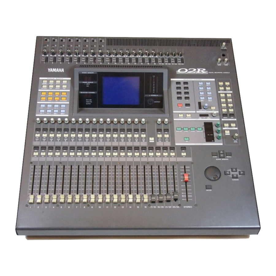
Controls and Connections Front Panel SELECTED CHANNEL controls Analog output controls Analog input controls Display screen and related controls DISPLAY ACCESS controls Monitor controls Scene memory controls Display controls Faders Digital Recording Console 02R User’s Guide... - Page 113 GAIN controls These controls adjust the gain of the input preamp. The analog input controls are not controlled or stored by the 02R automation and scene memory functions. To allow easy recall of the gain setting, the controls are detented.
- Page 114 T/B LEVEL STUDIO PHONES LEVEL LEVEL Digital Recording Console 02R User’s Guide Analog output controls T/B LEVEL control and microphone This control sets the volume level of the built-in talkback microphone. STUDIO LEVEL control This control sets the level of the signal sent to the STUDIO MONITOR OUTPUT connectors.
- Page 115 Button AUX 1 to 6 Set the channel levels to the auxiliary bus- ses. AUX 7 and 8 Set the channel levels to the auxiliary bus- ses and set the effect parameters. Digital Recording Console 02R User’s Guide Description Description...
- Page 116 Digital Recording Console 02R User’s Guide Display screen and related controls Edit Indicator SCENE MEMORY FADER STATUS INPUT 1 2 3 4 5 6 7 8 SELECTED CHANNEL MIC/LINE TAPE/RTN OUTPUT SCENE MEMORY indicator This 2-digit (7-segment) LED shows the currently selected Scene Memory program.
- Page 117 These buttons and controls set the pan position for the currently selected channel. EQ buttons and controls These buttons and controls set the equalization for the currently selected channel. Digital Recording Console 02R User’s Guide AUX 1 AUX 2 AUX 3 AUX 4...
- Page 118 MONO CONTROL ROOM SLATE TALKBACK SOLO LEVEL Digital Recording Console 02R User’s Guide Monitor controls STUDIO buttons These buttons select the monitor signal sent to the STUDIO MONITOR OUTPUT connectors. CONTROL ROOM buttons These buttons select the monitor signal sent to the C-R MONITOR OUT connectors.
- Page 119 SOLO bus. When you press the SOLO button again (cancel the SOLO function), the prior channel status is restored and the appropriate LEDs are switched back on. Digital Recording Console 02R User’s Guide EFF1 EFF2 FLIP...
- Page 120 Digital Recording Console 02R User’s Guide FLIP button This button interchanges the functions of MIC/LINE channels 1 to 16 and TAPE RETURN channels 1 to 16. This allows you to set the tape return levels with the Faders rather than the Tape Return controls.
-
Page 121: Rear Panel
C-R MONITOR OUT connectors These are balanced 1/4” phone connectors with a +4 dB nominal output level. They are wired TRS. They output the signal selected by the CONTROL ROOM buttons. Digital Recording Console 02R User’s Guide INPUT A INPUT A INPUT A... - Page 122 These are pairs of balanced 1/4" phone jacks with a –40 to +4 dB nominal input level. You can connect the return from a stereo effects unit (for example the YAMAHA D5000 digital delay) to these input channels. The signals from 2TR IN DIGITAL (1) can be routed to channels 17/18 and the signals from2TR IN DIGITAL (2) can be routed to channels 19/20.
- Page 123 WORD CLOCK connectors These are TTL/75 BNC connectors for transmitting (OUT) and receiving (IN) word clock signals. A switch is provided to apply a 75 terminator to the signal if the 02R is the last device in the chain. TO HOST connector This 8-pin MiniDIN connector is to plug a Macintosh or PC into the 02R for dedicated external system control.
- Page 124 Digital Recording Console 02R User’s Guide Signals input here are fed through to the CONTROL ROOM buttons (24) and are monitored in the control room or the studio. The outputs of a 2-track master recorder can be connected here for confidence monitoring and playback.
-
Page 125: Block Diagram
Block Diagram... - Page 126 Controls and Connections Digital Recording Console 02R User’s Guide...
-
Page 127: User Interface
SELECTED CHANNEL Controls ....... . . 23 Digital Recording Console 02R User’s Guide... -
Page 128: About The User Interface
CONFIGURATION Digital Recording Console 02R User’s Guide About the User Interface Digital Recording Console 02R user interface is powerful but very intuitive. There are two main methods of working with the 02R: • Use the DISPLAY ACCESS controls to modify one parameter at a time across the entire recording console. - Page 129 You can also select whether to send the signal pre or post fader. The [AUX 7] and [AUX 8] buttons also set the send levels to the corresponding auxiliary buss and can select pre or post fader. Digital Recording Console 02R User’s Guide...
-
Page 130: Display
CURSOR Digital Recording Console 02R User’s Guide However, these two sends are routed to the internal effects unit. Therefore, the buttons also allow you to select and set the effects parameters. Display The large backlit 320 240 pixel graphical display screen provides clear indication of mix settings and operating status. -
Page 131: Encoder Wheel
EQ ON/OFF. SCENE MEMORY Buttons STORE RECALL These buttons allow you to select, store and recall scene memories. The SCENE MEMORY current scene memory is indicated on the SCENE MEMORY LED. Digital Recording Console 02R User’s Guide... -
Page 132: Display Functions
Digital Recording Console 02R User’s Guide Display Functions The following table lists all the Digital Recording Console 02R display functions and briefly explains what they do. Display Function SCENE Store and recall mix scenes. DIGITAL I/O Sets digital I/O parameters and selects word clock. -
Page 133: Selected Channel Controls
The LEDs in the buttons illuminate to indicate the status of the channel. Note: You can customize your 02R so that when you adjust any of the controls in this group, the display switches to the ROUTING display function. See “Preferences”... - Page 134 Use the rotary encoder to adjust the pan position. The current position is indicated on the adjacent LED bargraph. Note: You can customize your 02R so that when you adjust any of the controls in this group, the display switches to the PAN display function. See “Preferences”...
-
Page 135: Mixing And Monitoring
Monitor Level Controls......... . 30 Digital Recording Console 02R User’s Guide... -
Page 136: Analog Inputs
For monitoring the output of a stereo tape recorder or another similar analog device, the 02R also has two pairs of 2TR IN phone connectors. Phantom Power Phantom power provides a +48 V DC power source for condenser type microphones. -
Page 137: Pad
The SIGNAL indicator is a green LED which illuminates when the input signal exceeds 10 dB below nominal. The analog input controls are not controlled or stored by the 02R automation and scene memory functions. To assist in easy recall of the gain setting, the GAIN controls are detented. -
Page 138: On Buttons
Fader positions are stored in scene memories. When a scene memory is recalled the faders automatically move to their stored positions. Fader positions are stored when the 02R is powered OFF. Even if faders are subsequently moved, they return automatically to their last positions when the 02R is powered ON again. -
Page 139: Analog Outputs
Analog Outputs The Digital Recording Console 02R is equipped with a pair of analog stereo out connectors, one pair XLR-type for connecting to professional equipment, the other phono (RCA) jacks. There are also two pairs of phone jacks to provide a stereo output to your control room and studio monitoring systems. -
Page 140: Monitor Level Controls
[ON] button. When you press the [SOLO] button again, the originally selected LEDs are illuminated again. Note: If the 02R is connected to other units with the digital cascade kit (CD8-CS), only the [SOLO] button on the cascade master unit is valid. See “Digital Cascade Kit (CD8-CS)”... -
Page 141: Mixing Display Functions
Preset EQ Program Parameters ........56 Digital Recording Console 02R User’s Guide... -
Page 142: Phase And Attenuation
5. Select another channel by pressing the [SEL] buttons of the CURSOR buttons. Digital Recording Console 02R User’s Guide Phase and Attenuation Phase The Phase ( ) function inverts the phase of the selected signal. When the phase of an channel is inverted against a corresponding channel, it can cause attenuation of both channels due to phase-cancellation. - Page 143 Shown below is the second screen – TAPE 1 through 16, EFF1 and EFF2, and STEREO output (attenuation only): Select this screen by pressing a [SEL] button for the tape or effect returns channels or the master stereo output channel. Digital Recording Console 02R User’s Guide...
-
Page 144: Delay
Digital Recording Console 02R User’s Guide Delay The DELAY display function is used to apply a small amount of delay to input or return signals to compensate for situations such as line or cabling delays or the gap between the record and playback heads (or circuitry) of your multitrack recorder. - Page 145 The same is true when the cursor is positioned over the ones digit of the samples field, or the tens, ones, or decimal digits of the milliseconds [mSEC] field. Digital Recording Console 02R User’s Guide...
-
Page 146: Pan And Balance
Digital Recording Console 02R User’s Guide Pan and Balance The PAN display function is used to pan and balance signals. The input channels, including the stereo input channels, and the tape and effect returns can be panned, and the stereo output can be balanced. -
Page 147: Stereo-Pair Pans
0% to 100%. To maintain a central balance, however, you must set both controls to a corresponding left and right values. For example, L5 and R5, or L10 and R10. Digital Recording Console 02R User’s Guide... -
Page 148: Pan Controls
LED of selected channel flashes. The indicator for the selected channel also flashes in the adjacent LED bargraph. Note: You can customize your 02R so that when you adjust any of the controls in this group, the display switches to the PAN display function. See “Preferences”... -
Page 149: Routing
MIC/LINE 1 through 16 and LINE 17/18 through 23/24: Select this screen by pressing a [SEL] button for one of the MIC/LINE channels. Digital Recording Console 02R User’s Guide Direct Out all ON Direct 1 to 8 Direct 9 to 16... -
Page 150: Routing Buttons
The LED inset each the button illuminates to indicate the status of the channel. Note: You can customize your 02R so that when you adjust any of the buttons in this group, the display switches to the ROUTING display function. See... -
Page 151: Metering
[ENTER] button. Metering The Digital Recording Console 02R features comprehensive signal level metering. The mono and stereo input channels, the tape and effect returns, and the auxiliary sends and buses are all metered using the METER display function. - Page 152 The dedicated control room output meter peak hold is not affected when other display functions are selected. Note: When the 02R reaches CLIP, digital signal distortion occurs. You must ensure this does not happen. Digital distortion is very unpleasant sounding. There are a several things you can do.
- Page 153 –36 –42 –48 If your Digital Recording Console 02R is equipped with the optional Meter Bridge – MB02, the METER display function controls both the selection of the meter points for each channel as well as switching the Peak Hold function ON or OFF.
-
Page 154: View
[ENTER] button. 5. To set the EQ, use the CURSOR buttons to select the EQ curve and press the [ENTER] button. The 02R will switch to the EQUALIZER display function. 6. To set the dynamics, select the dynamics curve with the CURSOR buttons and press the [ENTER] button. - Page 155 Displayed below the icon is the fader position in dB. See “Faders” on page 28 of the User’s Guide. Digital Recording Console 02R User’s Guide...
- Page 156 EFFECT TYPE display. It shows the name of the current effects program for the channel. Use the CURSOR buttons to select the effects program name and press the [ENTER] button. The 02R will switch to the EFFECT display function. See “Effects” on page 94 of the User’s Guide.
-
Page 157: Channel Library
STORE – This icon is used to store the current program to the library. Select the icon with the CURSOR buttons. Use the encoder wheel to select a program and press the [ENTER] button. The 02R will display a popup confirmation request message asking if you want to store your settings in the selected program. - Page 158 [ENTER] button. UNDO Operation When the 02R stores or recalls a program, the previous settings are always preserved in the UNDO buffer. If you discover you have made a mistake, you can always recall the UNDO buffer (displayed as “U:” in the scrolling list of programs).
-
Page 159: Equalizer
Equalizer The Digital Recording Console 02R is equipped with a four-band, fully parametric equalizer, with variable bandwidth, center frequency, gain, and ON/OFF parameters. EQ can be applied to the input channels (MIC/LINE 1 through 16, LINE 17/18 through 23/24), the tape and effect return channels (TAPE 1 through 16, EFF1 and EFF2), and the stereo output. - Page 160 Digital Recording Console 02R User’s Guide • Rotary icons – There is an icon for bandwidth (Q), center frequency (F), and gain (G) for each of the four bands, LOW, L-MID, H-MID, and HIGH. Use the CURSOR buttons to select the desired icon and adjust its value with the rotary encoder.
-
Page 161: Equalizer Controls
Use the [EQ ON] button to insert the equalization into the channel. Note: You can customize your 02R so that when you adjust any of the controls in this group, the display switches to the EQUALIZER display function. See “Preferences”... -
Page 162: Equalizer Programs
Digital Recording Console 02R User’s Guide Equalizer Programs These are the preset equalizer programs. Program Name Bass Drum 1 Bass Drum 2 Snare Drum 1 Snare Drum 2 Tom-tom 1 Cymbal High Hat Percussion E.Bass 1 E.Bass 2 Syn.Bass 1 Syn.Bass 2... -
Page 163: Equalizer Library
The bottom of the display contains the control button icons. Use the CURSOR buttons to select from the STORE, RECALL, COPY, PASTE, INS., and DEL. icons. Digital Recording Console 02R User’s Guide... - Page 164 STORE – This icon is used to store the current program to the library. Select the icon with the CURSOR buttons. Use the encoder wheel to select a program and press the [ENTER] button. The 02R will display a popup confirmation request message asking if you want to store your settings in the selected program.
- Page 165 UNDO Operation When the 02R stores or recalls a program, the previous settings are always preserved in the UNDO buffer. If you discover you have made a mistake, you can always recall the UNDO buffer (displayed as “U:” in the scrolling list of programs).
-
Page 166: Preset Eq Program Parameters
MIXING Display Functions Name Bass Drum 1 Bass Drum 2 Snare Drum 1 Snare Drum 2 Tom-tom 1 Cymbal High Hat Percussion E.Bass 1 Digital Recording Console 02R User’s Guide Parameter L-MID H-MID PEAKING PEAKING PEAKING 99Hz 265Hz 1.05kHz +3.5dB –3.5dB... - Page 167 944Hz 3.36kHz 0.0dB +3.5dB PEAKING PEAKING 1.05kHz 4.23kHz –8.5dB +4.5dB Digital Recording Console 02R User’s Guide Description HIGH H.SHELF Unlike program 9, this emphasizes the high range of the electric bass. 4.00kHz +0.5dB H.SHELF Use on a synth bass with emphasized low range.
- Page 168 A.G.Stroke 1 A.G.Stroke 2 A.G.Arpeggio 1 A.G.Arpeggio 2 Brass Section Male Vocal 1 Male Vocal 2 Female Vocal 1 Female Vocal 2 Chorus & Harmony Digital Recording Console 02R User’s Guide Parameter L-MID H-MID PEAKING PEAKING PEAKING 105Hz 1.00kHz 1.88kHz –2.0dB...
- Page 169 PEAKING 472Hz 2.37kHz –13.0dB +4.5dB PEAKING PEAKING 397Hz 6.72kHz +1.5dB +6.0dB Digital Recording Console 02R User’s Guide Description HIGH H.SHELF Use on the STEREO bus during mixdown. For more effect, try it with a 16.0kHz compressor. +6.5dB H.SHELF This is a variation on program 30.
- Page 170 Note: The programs 33 to 40 contain preset programs and are listed in the table above. However, you can store your own settings to these programs. Digital Recording Console 02R User’s Guide Parameter L-MID...
-
Page 171: Dynamics
Preset Dynamics Program Parameters ......76 Digital Recording Console 02R User’s Guide... -
Page 172: Dynamics Processors
Dynamics processors are generally used to correct or control signal levels. However, you can also use them creatively to shape the volume envelope of a sound. The Digital Recording Console 02R features comprehensive dynamics processors for all the input channels, tape returns, and the bus and stereo outputs. -
Page 173: Compressor
These values are obtained when the sampling frequency is 48 kHz. These values are obtained when the sampling frequency is 44.1 kHz. These values are obtained when the sampling frequency is 32 kHz Digital Recording Console 02R User’s Guide Value (55 points) - Page 174 - noticeable gain fluctuations. If it is set too long, the compressor may not have time to recover before the next high level signal appears, and it will be compressed incorrectly. Digital Recording Console 02R User’s Guide...
-
Page 175: Expander
These values are obtained when the sampling frequency is 48kHz. These values are obtained when the sampling frequency is 44.1 kHz. These values are obtained when the sampling frequency is 32 kHz Digital Recording Console 02R User’s Guide Value (55 points) -
Page 176: Compander
Width Threshold Input Level Digital Recording Console 02R User’s Guide Compander A compander is a compressor-expander - a combination of signal compression and expansion. The compander attenuates the input signal above the threshold as well as the level below the width. For very dynamic material, this program allows you to retain the dynamic range without having to be concerned with excessive output signal levels and clipping. -
Page 177: Gate And Ducking
These values are obtained when the sampling frequency is 48kHz. These values are obtained when the sampling frequency is 44.1 kHz. These values are obtained when the sampling frequency is 32 kHz Digital Recording Console 02R User’s Guide Value (55 points) - Page 178 For ducking, this determines how soon the ducker returns to its normal gain after the hold time has expired. Digital Recording Console 02R User’s Guide...
-
Page 179: Dynamics Display Function
Use the CURSOR buttons to select the desired icon and adjust its value with the encoder wheel. Press the [ENTER] button to turn the dynamics processor on or off. Digital Recording Console 02R User’s Guide... -
Page 180: Patching In A Processor
[ENTER] button to select the channels to patch the dynamics processor into. Digital Recording Console 02R User’s Guide Patching in a Processor DYNAMICS Icon The DYNAMICS ON/OFF icon is used to turn the dynamics processor on or off for the selected channel. -
Page 181: Dynamics Processor Meters
When the dynamics graph is a straight line at 45° from the bottom left corner of the graph, it indicates that the dynamics processor will have no effect on the input signal. Digital Recording Console 02R User’s Guide... -
Page 182: Key In And Link Indicators
Digital Recording Console 02R User’s Guide KEY IN and LINK Indicators The channel KEY IN settings and LINK settings are shown below. The settings can be changed with the CURSOR buttons, and the encoder wheel, or the [ENTER] button. The following table shows the meaning of... -
Page 183: Dynamics Library
The bottom of the display contains the control button icons. Use the CURSOR buttons to select from the STORE, RECALL, COPY, PASTE, INS., and DEL. icons. Digital Recording Console 02R User’s Guide... - Page 184 STORE – This icon is used to store the current program to the library. Select the icon with the CURSOR buttons. Use the encoder wheel to select a program and press the [ENTER] button. The 02R will display a popup confirmation request message asking if you want to store your settings in the selected program.
- Page 185 UNDO Operation When the 02R stores or recalls a program, the previous settings are always preserved in the UNDO buffer. If you discover you have made a mistake, you can always recall the UNDO buffer (displayed as “U:” in the scrolling list of programs).
-
Page 186: Preset Dynamics Program Parameters
Dynamics Preset Dynamics Program Parameters The “Release”, “Hold”, and “Decay” values shown in the following table are valid when the 02R is set at a sampling frequency of 44.1kHz. Name A.Dr.BD "CMP Compressor A.Dr.BD "EXP Expander A.Dr.BD "GAT Gate A.Dr.BD "CPH... - Page 187 –10 Ratio ( :1) Attack (ms) Outgain (dB) Knee hard Release (ms) Digital Recording Console 02R User’s Guide Value Description Gate for the same purpose as program 5. Soft compander for the same purpose as program 5. Expander for acoustic toms...
- Page 188 Compressor A.Guitar "CMP Compressor Strings1 "CMP Compressor Strings2 "CMP Compressor Strings3 "CMP Compressor Digital Recording Console 02R User’s Guide Type Parameter Threshold (dB) –9 Ratio ( :1) Attack (ms) Outgain (dB) Knee hard Release (ms) Threshold (dB) –18 Ratio ( :1)
- Page 189 Threshold (dB) –20 Ratio ( :1) Attack (ms) Outgain (dB) Knee Release (ms) Digital Recording Console 02R User’s Guide Value Description Compressor intended for brass sounds with fast and strong attack. Compressor for synth pad, intended to prevent diffusion of the sound.
- Page 190 CompanderH Compander(S) "CPS CompanderS Click Erase "EXP Expander Announcer "CPH CompanderH Easy Gate "GAT Gate Digital Recording Console 02R User’s Guide Type Parameter Threshold (dB) –8 Ratio ( :1) Attack (ms) Outgain (dB) Knee Release (ms) Threshold (dB) –9 Ratio ( :1)
- Page 191 Threshold (dB) –16 Ratio ( :1) Attack (ms) Outgain (dB) Knee Release (ms) Digital Recording Console 02R User’s Guide Value Description Ducking background music for voiceovers, typically keyed from the announcer’s channel. A template for a limiter using the soft compander program. This program has a slow release.
- Page 192 Dynamics Digital Recording Console 02R User’s Guide...
-
Page 193: Auxiliary Channels
About the 02R Auxiliaries ........ -
Page 194: About The 02R Auxiliaries
SEND LEVEL Digital Recording Console 02R User’s Guide About the 02R Auxiliaries The Digital Recording Console 02R has eight auxiliary send channels: AUX1, AUX2, AUX3, AUX4, AUX5, AUX6, AUX7, and AUX8. The auxiliary sends can be configured pre-fader or post-fader. -
Page 195: The Aux Buttons
Note: Avoid blocking the fader movements when the faders relocate to their auxiliary send positions by placing objects on the 02R. It is possible to damage the faders. The AUX LED of the FADER STATUS indicator will illuminate to indicate the fader status. - Page 196 Select this screen by pressing a SEL button for one of the MIC/LINE channels. Shown below is the second screen – TAPE 1 through 16, and EFF1 and EFF2: Select this screen by pressing a SEL button for the tape or effect returns channels. Digital Recording Console 02R User’s Guide...
-
Page 197: Stereo Input Channels
If you select a channel with a [SEL] button or the CURSOR buttons and double-click the [ENTER] button, all channels will be set to the same pre-fader or post-fader status as the selected channel. Digital Recording Console 02R User’s Guide... -
Page 198: Monitor Mix
To cater to this requirement, the 02R allows you to create a monitor mix using either AUX5 or AUX6. -
Page 199: Internal Effects
Preset Effects Program Parameters ....... . 98 Digital Recording Console 02R User’s Guide... -
Page 200: About Effects
Digital Recording Console 02R User’s Guide About Effects The Digital Recording Console 02R features two internal multi-effects stereo processors: Effect1 and Effect2. These are fed by AUX7 and AUX8, and the processed signals are returned via EFF1 RTN and EFF2 RTN, respectively. -
Page 201: Preset Effects Programs
REVERB VOCAL2 REV SN.ROOM REV SN.PLATE CHORUS->REVERB FLANGE->REVERB1 FLANGE->REVERB2 EARLY REF.1 EARLY REF.2 GATE REVERB Digital Recording Console 02R User’s Guide Program Name REVERSE GATE DELAY->EARLY REF DELAY L-C-R 1 DELAY L-C-R 2 CHORUS->DLY LCR MONODLY->CHORUS STEREO INI.DLY ECHO ECHO... -
Page 202: Aux 7 And Aux 8
Note: Avoid blocking the fader movements when the faders relocate to their auxiliary send positions by placing objects on the 02R. It is possible to damage the faders. The AUX LED of the FADER STATUS indicator will illuminate to indicate the fader status. - Page 203 Note: The AUX functions for AUX 7 and AUX 8 are restricted in their assignments to the effects buses. AUX 7 can only route to Effect2 and AUX 8 can only route to Effect1. Digital Recording Console 02R User’s Guide...
-
Page 204: Effects
Digital Recording Console 02R User’s Guide Effects The Digital Recording Console 02R is equipped with two internal multi-effects stereo processors. These processors have a startling range of special effects available to apply to your mix – shimmering reverbs, clean, precise delays, flanging and chorus, and a myriad of other effects are... -
Page 205: Effects Library
The bottom of the display contains the control button icons. Use the cursor buttons to select fromthe STORE, RECALL, COPY, PASTE, INS., and DEL. icons. Digital Recording Console 02R User’s Guide... - Page 206 STORE – This icon is used to store the current program to the library. Select the icon with the CURSOR buttons. Use the encoder wheel to select a program and press the [ENTER] button. The 02R will display a popup confirmation request message asking if you want to store your settings in the selected program.
- Page 207 UNDO Operation When the 02R stores or recalls a program, the previous settings are always preserved in the UNDO buffer. If you discover you have made a mistake, you can always recall the UNDO buffer (displayed as “U:” in the scrolling list of programs).
-
Page 208: Preset Effects Program Parameters
Density Same as program 1 THRU 280Hz Rev.Dly 1.0ms Rev.Bal Digital Recording Console 02R User’s Guide Range Reverb time. High frequency decay ratio. Reverb diffusion. Initial delay between the direct sound and early reflections. Average time between reflections. Low pass filter cutoff frequency. - Page 209 Rev.Time 2.4s Hi.Ratio Diff. Ini.Dly 16.0ms Density Same as program 1 8.0kHz THRU Rev.Dly 2.0ms Rev.Bal Range Same as program 1 Range Same as program 1 Range Same as program 1 Digital Recording Console 02R User’s Guide Description Description Description...
- Page 210 Rev.Time 2.4s Hi.Ratio Diff. Ini.Dly 0.1ms Density Same as program 1 7.0kHz THRU Rev.Dly 0.1ms Rev.Bal Digital Recording Console 02R User’s Guide Range Same as program 1 Range Same as program 1 Range Same as program 1 Description Description Description...
- Page 211 2.8s Hi.Ratio Diff. Ini.Dly 35.0ms Density Same as program 1 6.3KHz 80Hz Rev.Dly 30.0ms Rev.Bal 100% Range Same as program 1 Range Same as program 1 Range Same as program 1 Digital Recording Console 02R User’s Guide Description Description Description...
- Page 212 30.0ms 0.1~200.0ms 12.0KHz 1.0kHz~THRU 40Hz THRU~8.0kHz Depth 0~100% Digital Recording Console 02R User’s Guide Range Same as program 1 Range Same as program 1 Range Modulation frequency. Modulation depth. The amount of modulation. Modulation delay. The delay time before modulation begins.
- Page 213 Initial delay between the direct sound and early reflections. Number of early reflections. High frequency decay ratio. Feedback gain. The amount of signal returned to the effect. Low pass filter cutoff frequency. High pass filter cutoff frequency. Digital Recording Console 02R User’s Guide Description Description Description...
- Page 214 Same as program 20 Same as program 20 ER Num. Hi.Ratio FB.Gain 12.0kHz THRU Digital Recording Console 02R User’s Guide Range Range Type of reflections Time interval between the early reflections. Rate at which reflected sounds fade or decay. Reverb diffusion.
- Page 215 Feedback gain. The amount of signal returned to the effect. High frequency decay ratio. Low pass filter cutoff frequency. High pass filter cutoff frequency. Initial delay between the direct sound and early reflections. Range Digital Recording Console 02R User’s Guide Description Description Description...
- Page 216 THRU~8.0kHz Dly(L) 220.0ms 0.1~320.0ms Dly(R) 110.0ms 0.1~320.0ms Digital Recording Console 02R User’s Guide Range Chorus modulation frequency. Chorus depth. The amount of modulation. Chorus delay. The delay time before modulation starts. Left channel delay time. Right channel delay time. Centre channel delay time.
- Page 217 High pass filter cutoff frequency. Initial delay between the direct sound and early reflections. Feeds left channel signal back to the right channel. Feeds right channel signal back to the left channel. Range Range Digital Recording Console 02R User’s Guide Description Description Description...
- Page 218 EQ F 560Hz EQ G HSF F 3.2kHz HSF G +2dB Digital Recording Console 02R User’s Guide Range Modulation frequency. Amplitude modulation depth. Pitch modulation depth. Low shelving filter frequency. Low shelving filter gain. Chorus delay. The delay time before modulation starts.
- Page 219 High shelving filter gain. Range Modulation frequency. Amplitude modulation depth. Pitch modulation depth. Low shelving filter frequency. Low shelving filter gain. Equalizer frequency. Equalizer signal gain. High shelving filter frequency. High shelving filter gain. Digital Recording Console 02R User’s Guide Description Description Description...
- Page 220 –99 ~ +99% FB.G(2) –28% –99 ~ +99% Delay 25.0ms 0.1~255.0ms Digital Recording Console 02R User’s Guide Range Modulation frequency. Left to right pan depth. Front to rear pan depth. Low shelving filter frequency. Low shelving filter gain. Choose from L<–>R, L-->R, L<--R, Turn L, or Turn R.
- Page 221 This is a thin harmonizing effect obtained by setting a longer delay. Parameter Setting Pitch Fine(1) Fine(2) –10 Out(1) +100 Out(2) +100 Same as program 39 Same as program 39 Pan(1) Pan(2) FB.G(1) +10% FB.G(2) –10% Delay 60.0ms Range Digital Recording Console 02R User’s Guide Description...
- Page 222 Internal Effects Digital Recording Console 02R User’s Guide...
- Page 223 Fade Time ........... . 121 Digital Recording Console 02R User’s Guide...
-
Page 224: Scene Memories
Digital Recording Console 02R User’s Guide What are Scene Memories? Scene memories are a snapshot of all the Digital Recording Console 02R mixer setting. There are 64 mix scene memory locations. Each can be named for easy identification. They can be stored and recalled manually using the [STORE] and [RECALL] buttons. -
Page 225: What Is Stored In A Scene Memory
Scene number ”0“ (zero) and scene number “U” are read-only memory locations. Scene number “0 – Initial Data” contains the initial mix settings for the 02R. When you want to reset all the mixer settings to their initial values, recall this scene memory. -
Page 226: Storing Mix Scenes
Storage Confirmation When you save the mixer settings to a scene memory location, the 02R will display a popup confirmation request message. The popup has two control icons: “CANCEL” and “EXECUTE”, as shown below: Note: You can customize your 02R to prevent the confirmation popup from... -
Page 227: Naming A Scene Memory
INSERT, DELETE, COPY, or PASTE icons. At the bottom of the right side of the display is the Memory Protect check box. When this box is checked, all scene memory is protected from the storage operations. Digital Recording Console 02R User’s Guide... -
Page 228: Protecting Scene Memories
Digital Recording Console 02R User’s Guide Character Set A scene memory name can be up to 16 characters long and can contain any of the following characters: “ & Control Icons • INSERT – This icon is used to insert blank characters into the title edit box at the current cursor location. -
Page 229: Recalling Scene Memories
Note: When recalling mix scenes, be aware that volume levels may change suddenly as channels are switched ON and faders moved. The 02R has a feature that allows you to fade the levels as a scene memory is loaded, but it cannot compensate for the sudden burst of a channel suddenly being switched on. -
Page 230: Fader Recall Safe
Digital Recording Console 02R User’s Guide Fader Recall Safe The Digital Recording Console 02R has two methods of protecting the system from sudden volume level changes when a scene memory is recalled. You can select individual channels to safety. When the scene memory is recalled, the fader level will not change from the level it was set to in the previous mix. -
Page 231: Fade Time
In order for the fade time you set to have any effect, you must store the scene memory (see “Storing Mix Scenes” on page 116 of the User’s Guide). Digital Recording Console 02R User’s Guide... - Page 232 Scene Memories Digital Recording Console 02R User’s Guide...
-
Page 233: Automation
Event Extract ..........140 Digital Recording Console 02R User’s Guide... -
Page 234: What Is The Automation Function
You can store the current mix in any of the 16 automix memories. The default memory capacity of the 02R is 512kB. Total size of the current mix and the 16 AUTOMIX memories should be under 512kB. If you find... - Page 235 MIDI data filer, then clear the memories. You can also expand the available memory with 1Mbyte expansion kits (ME4M). You can install up to two of these kits in the 02R, resulting in a maximum memory size of 2.5Mbytes.
-
Page 236: What Is Timecode
• Internal timecode When you synchronize the 02R to an external device such as a multitrack recorder or MIDI sequencer, the external device will provide SMPTE or MTC timecode to allow the automix to synchronize with the data on the recorder or sequencer. - Page 237 MIDI sequencers or a multitrack recorder that has MTC output jacks. Use a MIDI cable to plug the MTC output connector of the controlling device into the TIME CODE INPUT – MTC connector on the back of the 02R. TIME CODE INPUT (MTC) Note: When transmitting MTC to the 02R, you should use a dedicated output on the connected device.
-
Page 238: Automation Function
Note: You should also refer to the section “Mixing and Automation” on page 67 of the Getting Started Guide for additional tips on the operation of the 02R automation system. -
Page 239: Main Screen
The bottom row contains the automation transport control icons. Select from the following: • AUTOREC – recording starts when the 02R receives timecode. • REC – places the 02R in record ready mode. •... - Page 240 Digital Recording Console 02R User’s Guide Time Code Display The 02R displays the received timecode in this large area on the screen. If you select INT (internal) timecode, the timecode display immediately starts to count the time. You can reset this value with the “INT Start Time”...
- Page 241 AUTOREC – Selecting this icon will start AUTOMIX recording when the 02R receives timecode, even if it is not in REC ready mode. You can use this key when you do not want to press the REC ready key many times.
- Page 242 PLAY – Selecting this icon when timecode is being received and the AUTOMIX is stopped will play back the automix. Selecting this icon while the 02R is in record ready mode will start a punch-in recording. Note: A channel must be selected with its [SEL] button in order for any automation events to be recorded.
-
Page 243: Memory Management
UNDO (which allows you to undo the last edit operation) and NEW (which creates a new automix in the current buffer) icons. The last row on the bottom contains the automation transport control icons (AUTOREC, REC, PLAY, STOP, or ABORT). Digital Recording Console 02R User’s Guide... - Page 244 Select the icon with the CURSOR buttons. Use the encoder wheel to select an AUTOMIX program and press the [ENTER] button. The 02R will display a popup confirmation request message asking if you want to store your settings in the selected program. The popup has two control icons: “CANCEL”...
- Page 245 Select the icon with the CURSOR buttons. Use the encoder wheel to select an AUTOMIX program and press the [ENTER] button. The 02R will display a popup confirmation request message asking if you want to recall the selected program. The popup has two control icons: “CANCEL”...
-
Page 246: Fader Edit
You can control how the faders will return to the previously recorded values when you perform an overdub. If you select RETURN, when the 02R plays back the overdub, it will return the fader to the location previously recorded in the data. You can set a value between 0.0 and 3.0 seconds over which the fader will change levels. - Page 247 Refer to the following diagram: If the fader is moved to a position lower than the previously recorded position Digital Recording Console 02R User’s Guide If the fader is moved to a position higher than the previously recorded position...
-
Page 248: Event Edit (Memory)
4. Use the CURSOR buttons to select the DELETE icon and press [ENTER] to delete the current event. Digital Recording Console 02R User’s Guide Event Edit (MEMORY) The fourth AUTOMIX display function is the Event Edit (MEMORY) screen shown below: The display consists of a table listing Time Code, Memory (event), and Channel. -
Page 249: Event Edit (Ch On)
Use the CURSOR buttons to select the timecode field and adjust the timecode value to suit. Change the channel or the ON/OFF values if required. When you change the timecode value for an event, the events are automatically sorted in timecode location. Digital Recording Console 02R User’s Guide... -
Page 250: Event Extract
AUX8), the “In Time” timecode indicator, and the “Out Time” timecode indicator. Below are the EXTRACT and UNDO control icons. EXTRACT Selecting this icon causes the 02R to delete all the applicable events starting from the “In Time” timecode location up to, but not including, the “Out Time” timecode location. -
Page 251: Midi
MIDI and the 02R........ -
Page 252: Midi And The 02R
MIDI implementation. You will find that for most operations, MIDI is not required – indeed, because of the complexity of the 02R and the number of parameters available for adjustment, it is not possible to operate the unit by sending MIDI control change messages. -
Page 253: Setup
Shown below is the first MIDI display function – the MIDI Setup screen: Receive Channel Use these functions to set the Receive Channel, and select whether the 02R will receive Program Change and Parameter Change messages. When you change a Receive Channel item, it also changes the corresponding Transmit Channel item. -
Page 254: Program Change Assign
[ENTER] button. Digital Recording Console 02R User’s Guide Program Change Assign The 02R uses MIDI Program Change messages to recall scene memories. Display Screen Shown below is the second MIDI display function – the MIDI Program Change Assign screen: The default Program Change Assign table consists of a mapping of Program Change numbers 1 through 64 to Scene Memories 1 through 64. -
Page 255: Bulk Dump/Request
Display Screen Shown below is the third MIDI display function – the MIDI Bulk Dump & Request screen: Type This function allows you to select eight types of 02R data to Bulk Dump or Bulk Request: • Scene Memories •... - Page 256 MIDI device. • REQUEST ALL – the 02R will request all the programs or memories of the selected data type from the connected MIDI device. When you execute one of the above commands, the 02R displays its current status in the STATUS field at the bottom of the display.
-
Page 257: Groups And Pairs
Pairing Channels ..........150 Digital Recording Console 02R User’s Guide... -
Page 258: Grouping Faders
Digital Recording Console 02R User’s Guide Grouping Faders The Digital Recording Console 02R allows you to group the faders for multiple fader control using only one fader. This makes it easy to control several faders simultaneously. The input channel and the tape and effect returns can be grouped. -
Page 259: Grouping Mutes
Grouping Mutes The 02R also allows you to group channel status controls for multiple channel control using only one channel ON button. The channels in a group can be on or off depending on their status when they were grouped. -
Page 260: Pairing Channels
The 02R allows you to link the input channels – MIC/LINE 1 through 16 – the tape return channels – TAPE 1 through 16 –... - Page 261 Shown below is the second PAIR display function - the Aux Pair screen. You can pair the auxiliary send channels – AUX 1 through AUX 6: Use the CURSOR buttons to select a channel pair and press the [ENTER] button to pair or separate them. Digital Recording Console 02R User’s Guide...
- Page 262 Groups and Pairs Digital Recording Console 02R User’s Guide...
-
Page 263: Digital I/O, Setup, And Utilities
02R System Initialization ........ -
Page 264: Word Clock Select
When you are using a digital device – such as a DAT mastering recorder or a modular digital multitrack recorder – connected to the 02R, all the digital devices in the system, including the 02R, should synchronize the wordclock being supplied by one master device. - Page 265 The left side of the display is a list of the cards in the four option slots of the 02R. The indication varies depending on the type of optional card being used: • Cascade (CD8-CS) • ADAT (CD8-AT) • TDIF-1 (CD8-TDII) •...
-
Page 266: Input Signal Select
Digital Recording Console 02R User’s Guide Input Signal Select The 02R has 24 built-in analog input connectors; the individual input channels (MIC/LINE 1 through 16) and the stereo input channels (LINE 17/18 through 23/24). You can route two of the 2-track digital inputs to the stereo input channels (2TR IN D1 to LINE 17/18 and 2TR IN D2 to LINE 19/20). -
Page 267: Cascade Configuration
Cascade Configuration Just like the modular digital multitrack recorders it is intended to work with, the 02R was designed to be easily expandable from a basic 16-track (40 input) system up to a 64-track (160 input) system. It uses Cascade Digital I/O card kits (CD8-CS) to accomplish this. - Page 268 (maximum 3). You can select from 0 to 3 as the unit ID. You can only set this item when a cascade card is inserted in the 02R and set to IN. When the screen is greyed-out, the ID is automatically set to 0.
-
Page 269: Dither
Dither When you connect a number of digital audio devices together, you may find their digital word size is different. For example, the 02R uses a 20-bit word size for input and output and a 32-bit word size for internal processing. -
Page 270: Solo
“Solo Safe” channels and press the [ENTER] button to enable/disable the selected channel. Digital Recording Console 02R User’s Guide Solo The SETUP display function consists of two screens: the “Solo” screen and the “Preferences” screen. Display Screen Shown below is the first SETUP display function –... - Page 271 The LED inset in the [ON] button you select is illuminated steadily. If you selected “Last Solo” in the Status command, only the last channel you select will be soloed. 3. Press the [SOLO] button again to cancel the solo function. Digital Recording Console 02R User’s Guide...
-
Page 272: Preferences
Digital Recording Console 02R User’s Guide Preferences The Digital Recording Console 02R is a very flexible mixer. You can customize its behaviour to suit your needs using the preferences options. Display Screen Shown below is the second SETUP display function – the Preferences... - Page 273 You should leave this option in its default state when your 02R is going to be operated by an inexperienced person. Forcing them to respond to a confirmation message may prevent the accidental loss of your valuable data. When you confirm a STORE operation, any existing data in the selected program location will be overwritten.
- Page 274 Digital Recording Console 02R User’s Guide • DIO Warning OFF – With this option selected, the 02R will not report a warning when an error is detected in the digital signals being input from one of the digital I/O cards. When the 02R detects an error, the message “DIGITAL I/O Error!”...
-
Page 275: Oscillator
This is especially important when the multitrack recorder is analog. The 02R has an oscillator function that allows you to send 100 Hz, 1 kHz, and 10 kHz sine waves and white noise to the auxiliary and output buses and the stereo bus. -
Page 276: Emphasis Monitor
– the 02R can compensate by applying de-emphasis to the signal before further processing. Note: When the 02R receives data that has been processed with emphasis ON, it will automatically process the data by applying de-emphasis. It will continue processing the signal internally and will subsequently out put the data with emphasis OFF. -
Page 277: Channel Status Monitor
In this case, the Emphasis, Category, and Copy columns will show “---”. • Emphasis – This shows the status of emphasis of the control bit. “ON”, “OFF” or “???” (unknown) will be shown. Digital Recording Console 02R User’s Guide... - Page 278 Digital Recording Console 02R User’s Guide • Category – This shows the status of the “category bit” which is implemented only for the IEC958 Part2 (Consumer) format. The following items are included: General – Used temporarily. Laser Optical – Laser optical device D/D Conv –...
-
Page 279: Battery Check
Note: If this screen appears, your important data in memory, such as scene memories, automix memories, and libraries, may be lost. Ask your nearest Yamaha dealer or Yamaha Service Center to replace the battery as soon as possible. Digital Recording Console 02R User’s Guide... -
Page 280: 02R System Initialization
Digital Recording Console 02R User’s Guide 02R System Initialization This operation allows you to reset the Digital Recording Console 02R to its factory default settings. This operation deletes all scene memories, automix programs, and clears all user library programs from the channel, dynamics, effect, and equalizer libraries. -
Page 281: Installing Options
Installing 02R Options ........ -
Page 282: Digital Recording Console 02R Options
There are a number of options you can add to your Digital Recording Console 02R. Some of these options add to the convenience and appearance of the 02R, such as the peak meter bridge (MB02) or the wooden side panels (W02SP). There is also a memory expansion kit (ME4M) which allows you to add up to 2 MB of additional memory for the automation system. - Page 283 8, two pairs of the auxiliary buses 1 through 8 to the cascade card’s AUX A and AUX B buses, the STEREO bus, and the SOLO bus of two or more 02R’s. One 02R is the cascade master, the others are slaves.
- Page 284 Take your 02R to your YAMAHA dealer or authorized service centre for installation of the ME4M kit. Wooden Side Panels These Wooden Side Panels (W02SP) attach to either side of the 02R to give it an attractive appearance. Digital Recording Console 02R User’s Guide...
-
Page 285: Installing 02R Options
BEFORE YOU OPEN ANY OF THE OPTIONAL SLOT COVERS! Note: Before you install a card in the 02R, be certain to turn the power off. Not only do you risk electrical shock, you can also damage either the 02R or the optional card. - Page 286 BEFORE YOU OPEN ANY OF THE OPTIONAL SLOT COVERS! Note: Before you install a card in the 02R, be certain to turn the power off. Not only do you risk electrical shock, you can also damage either the 02R or the optional card.
- Page 287 TO PREVENT ELECTRICAL SHOCK, ENSURE THE 02R IS POWERED OFF BEFORE YOU FASTEN ANY CONNECTORS OR UNDO ANY SCREWS! Note: Before you install the MB02 on the 02R, be certain to turn the power off. Not only do you risk electrical shock, you can also damage either the 02R or the MB02.
-
Page 288: Analog I/O Card Ad/Da (Cd8-Ad)
If the card was installed properly, the system software should correctly identify it in the appropriate slot. 2. Make the required connections between the 02R and your analog devices. You should use the highest quality connecting cables you can afford to maintain the best possible signal quality. - Page 289 2. If your AES/EBU compatible multitrack digital recorder has a dedicated wordclock output connector, plug it into the WORD CLOCK – IN connector on the back of the 02R and turn the 75 terminator switch on. If there is no dedicated wordclock output, you can obtain the wordclock signal required from one of the digital interconnect lines.
- Page 290 It is always important to observe the correct order for powering up equipment in a studio. Start with the AES/EBU compatible multitrack and mastering recorders and the signal processors, then the 02R, and finally the monitoring amplifiers and other downstream gear.
-
Page 291: Digital I/O Card - Adat (Cd8-At)
Plug the OUT connector of the CD8-AT to the OPTICAL IN connector of the ADAT recorder. If you have installed more than one CD8-AT in the 02R and have more than one ADAT recorder, connect it in the same manner as the first unit. - Page 292 (no discrepancy between the input and selected wordclock frequencies), check the connections between the ADAT modular digital multitrack recorder and the 02R.Check that the ADAT recorder is powered on. 3. Use the CURSOR buttons to select the wordclock source.
-
Page 293: Digital Cascade Kit (Cd8-Cs)
The cascade I/O card (CD8-CS) is a single slot card. At least one cascade I/O card should be installed in each 02R. If you are connecting more than two units, the middle units should have two cards. The cascade I/O cards should be installed in SLOT3 or SLOT4. - Page 294 Digital Recording Console 02R User’s Guide 3. Use a BNC cable to plug the WORD CLOCK – OUT connector on the back of the first 02R into the WORD CLOCK – IN connector on the second 02R. The 02R that is the cascade master should be receiving a wordclock signal from a wordclock master device, such as a modular digital multitrack recorder or other appropriate device.
- Page 295 If you have four 02R units cascaded together, the cascade master should be set to ID=3. Note: If you connect more than four 02R units together, you will have to adjust the delay to compensate for signal processing time. See “Delay and Cascade”...
-
Page 296: Solo Function
See “Solo” on page 160 of the User’s Guide for further details. 3. On the 02R cascade master, press the [SOLO] button. The LEDs inset in the [ON] buttons of all the cascaded 02R units will flash. 4. Press the [ON] button of the channel (or channels) that you want to solo. - Page 297 Use the special cable to plug the connector of the CD8-AT to the DIGITAL I/O connector of the TASCAM DA-88 recorder. If you have installed more than one CD8-TDII in the 02R and have more than one TASCAM DA-88 recorder, connect it in the same manner as the first unit.
- Page 298 BNC cable between the WORD SYNC OUT connector on the DA-88 and the WORD CLOCK IN connector on the 02R.Check that the DA-88 is powered 3. Use the CURSOR buttons to select the wordclock source.
-
Page 299: Peak Meter Bridge (Mb02)
–15 –42 –15 –18 –18 –48 –24 –24 –30 –30 –36 –36 –42 –42 –48 –48 Digital Recording Console 02R User’s Guide SELECT BUS·AUX EFF 2 LINE CLIP –3 –6 PEAK HOLD –9 –12 –15 –18 –24 –30 –36 –42... - Page 300 Digital Recording Console 02R User’s Guide 4. PEAK HOLD button This button used to enable or cancel the peak hold function of the meters. Note: The operation of this button duplicates the function of the PEAK HOLD icon in the METER display function. See “Metering” on page 41 and “Peak Hold”...
-
Page 301: Specifications
Bulk Dump and Request Format....... . . 213 Digital Recording Console 02R User’s Guide... -
Page 302: General Specifications
* Hum & Noise are measured with a 6 dB/octave filter @12.7 kHz; equivalent to a 20 kHz filter with an infinite dB/oc- tave attenuation. * Sampling Frequency: Internal 48 kHz Digital Recording Console 02R User’s Guide Specifications Internal 44.1 kHz, 48 kHz External (32 kHz –6%) to (48 kHz +6%) - Page 303 18 dB (0.5 dB steps) HPF = ON/OFF Input channel (MIC/LINE 1 through 24) L-MID Digital Recording Console 02R User’s Guide MIC/LINE 1 through 8 MIC/LINE 1 through 16 LINE 17/18 through 23/24 MIC/LINE 1 through 16 MIC/LINE 1 through 16...
- Page 304 AUX 5 AUX 6 AUX 7 AUX 8 Digital Recording Console 02R User’s Guide Input channel (MIC/LINE 1 through 24) –54 dB to 0 dB 1, 1.1, 1.3, 1.5, 1.7, 2, 2.5, 3, 3.5, 4, 5, 6, 8, 10, 20,...
- Page 305 Aux send AUX8. EFF2 can only send to AUX7.) 33 positions (L = 16 to 1, C, R = 16 to 1) Input channel (MIC/LINE 1 through 24) Effect Return (EFF 1 through 2) Digital Recording Console 02R User’s Guide...
- Page 306 Pre fader / After pan Peakhold: ON/OFF Meter 12 points displays of the pre-EQ / post-EQ / post-fader levels of all channel input are displayed on the screen. Digital Recording Console 02R User’s Guide Effect Return (EFF 1 through 2)
- Page 307 ON/OFF Slate ON/OFF Level control A/D converter 16 bit linear / 64 times oversampling STEREO OUT BUS OUT (BUS1 through BUS8) AUX OUT (AUX1 through AUX8) CONTROL ROOM MONITOR OUT STUDIO MONITOR OUT TALKBACK Digital Recording Console 02R User’s Guide...
-
Page 308: Input Specifications
Input Specifications Input PAD GAIN connection impedance –60 CH INPUT 3k (XLR) MIC/LINE 1 4k (Phone through16 jack) –16 Digital Recording Console 02R User’s Guide 120V 240V 230V 685 mm 672 mm CD8-AT CD8-AD CD8-TDII CD8-Y CD8-AE, CD8-AE-S Actual For use... - Page 309 – 6 dB (388mV) –10 dB 600 lines (245mV) + 4 dB 600 lines (1.23V) –10 dBV 600 lines (316mV) Digital Recording Console 02R User’s Guide Input level Mixer Max. connector Nominal before clip –40 dB –20 dB (7.75mV) (77.5mV) Phone Jack...
-
Page 310: Output Specifications
(STEREO OUT) WORD CLOCK IN WORD CLOCK OUT MIDI IN MIDI OUT MIDI THRU TO HOST METER MTC IN TC IN Digital Recording Console 02R User’s Guide Actual For use source with Nominal impedance nominal + 4 dB 600 lines (1.23V) -
Page 311: Dimensions
Specifications Dimensions W : 672 Specifications and external appearance are subject to change without notice. Digital Recording Console 02R User’s Guide... -
Page 312: Options
DA88/DA38 (BUS/DIRECT OUT, TAPE IN) TDIF-1 ADAT (BUS/DIRECT OUT, TAPE IN) AES/EBU (BUS/DIRECT OUT, TAPE IN) YAMAHA (BUS/DIRECT OUT, TAPE IN) CASCADE (BUS/DIRECT OUT, TAPE IN) Digital Recording Console 02R User’s Guide For use with nom- Sensitivity inal –6 dB... -
Page 313: Troubleshooting
Is the switch for the item to be transmitted/received (Program Change, Parameter Change) turned The fader movement is not consistent. • Calibrate the faders. See “Fader Calibration” on page 170 of the User’s Guide. Digital Recording Console 02R User’s Guide... -
Page 314: Error Messages
Byte count for the received bulk data is not correct. 2TR-D1 cannot be routed to line 17/18. (The signal at 2TR-D1 is not syncing with the 02R, or 2TR-D1 has been selected in the C-R monitor section.) 2TR-D2 cannot be routed to line 19/20. (The signal at 2TR-D2 is not syncing with the 02R, or 2TR-D2 has been selected in the C-R monitor section.) - Page 315 In/out time setting is incorrect. The internal battery voltage is getting very low. Back-up the setup data stored in the 02R (see “Bulk Dump/Request” on page 145 of the User’s Guide), and ask your dealer to replace the battery. Consult the nearest YAMAHA service center.
- Page 316 The recall operation was undone. The store operation was undone. The device for synchronization (selected from the 02R correct word clock. Re-configure the synchronization s There are more than two cascade cards or too many ca or “out” setting. Check the slot condition, and turn the p 02R again.
-
Page 317: Midi Data Format
MIDI Data Format Specifications 1. General remarks This section describes the MIDI functionality of the 02R. Electrical characteristics and message formats are in compliance with MIDI standard 1.0. 2. Messages transmitted and received 2-1. Program change Transmission/reception can be turned ON or OFF using the “MIDI Setup” display function (see “Setup” on page 143 of the User’s Guide). - Page 318 KEY REMOTE T (KEY REMOTE) (RESPONSE FOR PARAMETER REQUEST) SYSTEM EXCLUSIVE BULK DUMP $F0H, $43H, $0nH BULK REQUEST $F0H, $43H, $2nH MIDI IN PROGRAM CHANGE $CnH ACTIVE SENSE $FEH Digital Recording Console 02R User’s Guide MIDI CH? MIDI OUT PBM ECHO ON...
- Page 319 Digital Recording Console 02R User’s Guide 5. Receive Condition PGM OMNI ON MIDI CH? MIDI IN PGM ECHO ON MTC IN PGM R $CnH PROGRAM CHANGE PARAM R SYSTEM EXCLUSIVE $F0H,$43H,$1nH PARAMETER CHANGE $F0H,$43H,$3nH PARAMETER REQUEST SYSTEM EXCLUSIVE $F0H, $43H, $0nH BULK DUMP...
-
Page 320: Parameter Change And Request Format
H) high 7 bits of 14 bits address address( L) low 7 bits of 14 bits address count End Of Exclusive System Exclusive Message Manufacturer's ID No.(YAMAHA) n=0-15(Tx/Rx Channel No.1-16) MODEL ID (02R) (type number, bit6 = 0( byte operation)) Digital Recording Console 02R User’s Guide... - Page 321 0ddddddd dd1 0ddddddd dd2 11110111 F7 Digital Recording Console 02R User’s Guide address( H) high 7 bits of 14 bits address address( L) low 7 bits of 14 bits address data( H) high 4 bits of 8 bits data( 0000dddd)
- Page 322 MODEL ID (02R) key remote (type number) key No.( H) high 7 bits key No.( L) low 7 bits key on( 1)/off( 0) End Of Exclusive Digital Recording Console 02R User’s Guide Tx only Tx only Tx only Tx only Tx only...
- Page 323 00111101 3d PARAM TYPE 00011001 1A DATA 0ddddddd dd0 0ddddddd dd1 11110111 F7 Digital Recording Console 02R User’s Guide PARAMETER CHANGE (fader remote) System Exclusive Message Manufacturer's ID No.(YAMAHA) n=0-15(Tx/Rx Channel No.1-16) MODEL ID (02R) fader remote (type number) No. (0-20:fader 1-21(st mas)
-
Page 324: Bulk Dump And Request Format
Scene Memory Bulk Dump Format System Exclusive Message Manufacturer's ID No.(YAMAHA) n=0-15(Tx/Rx Channel No.1-16) Universal Bulk Dump 4074(2016x2+32+10)bytes m=0-64,127(Scene Memory No.0-64,current) id 1 id 16 title1 title16 Scene Memory(2016x2bytes) ee=(INVERT('L'+'M'+...+dsH+...+deL)+1) AND 7Fh End Of Exclusive Digital Recording Console 02R User’s Guide... - Page 325 00110110 36 00110111 37 01001101 4D DATA NAME 0mmmmmmm mm 11110111 F7 Scene memory transmission from the 02R is possible for programs 1-64 only. Program Change Assignment Table Bulk Dump Format STATUS 11110000 F0 ID No. 01000011 43 SUB STATUS 0000nnnn 0n FORMAT No.
- Page 326 End Of Exclusive System Exclusive Message Manufacturer's ID (YAMAHA) n=0-15(Tx/Rx Channel No.1-16) Universal Bulk Dump End Of Exclusive Setup Memory Bulk Dump Format System Exclusive Message Manufacturer's ID No.(YAMAHA) n=0-15(Tx/Rx Channel No.1-16) Universal Bulk Dump 266(128x2+10)bytes Digital Recording Console 02R User’s Guide...
- Page 327 01000001 41 00110110 36 00110111 37 01010011 53 DATA NAME 00100000 20 11110111 F7 Digital Recording Console 02R User’s Guide Setup Memory Bulk Dump Format Setup Memory(128x2bytes) ee=(INVERT('L'+'M'+...+dsH+...+deL)+1) AND 7Fh End Of Exclusive System Exclusive Message Manufacturer's ID (YAMAHA) n=0-15(Tx/Rx Channel No.1-16)
- Page 328 Manufacturer's ID No.(YAMAHA) n=0-15(Tx/Rx Channel No.1-16) Universal Bulk Dump 72(23x2+16+10)bytes m=0-127(Effect Library No.1-128) title1 title16 Effect Library Memory(23x2bytes) ee=(INVERT('L'+'M'+...+dsH+...+deL)+1) AND 7Fh End Of Exclusive System Exclusive Message Manufacturer's ID (YAMAHA) n=0-15(Tx/Rx Channel No.1-16) Universal Bulk Dump Digital Recording Console 02R User’s Guide...
- Page 329 00111000 38 01000001 41 00110110 36 00110111 37 01000101 45 DATA NAME 0mmmmmmm mm 11110111 F7 Effect library transmission from the 02R is possible for programs 41-128 only. STATUS 11110000 F0 ID No. 01000011 43 SUB STATUS 0000nnnn 0n FORMAT No.
- Page 330 00111000 38 01000001 41 00110110 36 00110111 37 01010001 51 DATA NAME 0mmmmmmm mm 11110111 F7 Equalizer library transmission from the 02R is possible for programs 33-128 only. STATUS 11110000 F0 ID No. 01000011 43 SUB STATUS 0000nnnn 0n FORMAT No.
- Page 331 00111000 38 01000001 41 00110110 36 00110111 37 01011001 59 DATA NAME 0mmmmmmm mm 11110111 F7 Dynamics library transmission from the 02R is possible for programs 41-128 only. STATUS 11110000 F0 ID No. 01000011 43 SUB STATUS 0000nnnn 0n FORMAT No.
- Page 332 Channel Library Bulk Dump Format 122(48x2+16+10)bytes m=0-63(Channel Library No.1-64) title1 title16 Channel Library Memory(48x2bytes) ee=(INVERT('L'+'M'+...+dsH+...+deL)+1) AND 7Fh End Of Exclusive System Exclusive Message Manufacturer's ID (YAMAHA) n=0-15(Tx/Rx Channel No.1-16) Universal Bulk Dump m=0-63(Channel Library No.1-64) Digital Recording Console 02R User’s Guide...
- Page 333 0ddddddd dsH 0ddddddd dsL 0ddddddd deH 0ddddddd deL CHECK SUM 0eeeeeee ee 11110111 F7 Digital Recording Console 02R User’s Guide End Of Exclusive Automix Bulk Dump Format System Exclusive Message Manufacturer's ID No.(YAMAHA) n=0-15(Tx/Rx Channel No.1-16) Universal Bulk Dump 2078(1024x2+20+10)bytes m=0-15(Automix No.1-16)
- Page 334 00110110 36 00110111 37 01000001 41 DATA NAME 0000mmmm 0m 11110111 F7 Automix Bulk Dump Request Format System Exclusive Message Manufacturer's ID (YAMAHA) n=0-15(Tx/Rx Channel No.1-16) Universal Bulk Dump m=0-15(Automix No.1-16) End Of Exclusive Digital Recording Console 02R User’s Guide...
- Page 335 Specifications Digital Recording Console 02R User’s Guide...
-
Page 336: Glossary
A/D converters to allow the anti-aliasing filter to be performed in the digital domain. See over-sampling. Attenuation – After the signal has been converted to digital, the 02R can apply numerous forms of signal processing, such as equalization or effects. - Page 337 DAT cassette – Metal chrome cassette tape (thickness 13µm, width 8.8mm). Delay – A delay applied to the input signals processed by the 02R to compensate for signal processing delays, for example caused by the gap between the record and playback heads of a multitrack recorder.
- Page 338 6dB per digital bit. A 20-bit system has a theoretical dynamic range of 120 dB. The 02R has a specified dynamic range of 105 dB. Dynamics Library – An area in 02R memory used to access and store dynamics settings –...
- Page 339 An XLR-type connector and a shielded cable is typically used. Internal Effects – The 02R is equipped with two internal multi-effects stereo processors. These processors have a startling range of special effects available to apply to your mix – shimmering reverbs, clean, precise delays, flanging and chorus, and a myriad of other effects are available.
- Page 340 Phase – Phase is the frequency coherence of a signal. If two signals are out of phase, the trough of the first waveform corresponds with the peak of the second, resulting in cancellation. The 02R can invert the phase of the input signals, which allows you to compensate for incorrectly wired conductors and so forth.
- Page 341 The bands 100–200, 800–1600, and 3000–6000 all contain the same amount of energy. Word – One sample of audio data. In the 02R, a word is 20-bits. Wordclock – Wordclock is a sync pulse which allows devices to determine where the start of each digital word is.
-
Page 342: References And Further Reading
The Art of Digital Audio, John Watkinson, Focal Press (Butterworth Group), 1990. • The MIDI Ins, Outs & Thrus, Jeff Rona, Hal Leonard Publishing, 1992. • Yamaha Sound Reinforcement Handbook, Gary Davis and Ralph Jones, second edition, Hal Leonard Publishing Corporation, 1990. Digital Recording Console 02R User’s Guide... - Page 343 Glossary Digital Recording Console 02R User’s Guide...
-
Page 344: Index
A-B comparisons ...87 description...84 effects return ...84 fader status...85 pre-fader or post-fader configuration ...87 send level control ...85 stereo input channels...87 AUX 1 button...85 AUX 1 display function Mic/Line screen ...86 PRE/POST icon ...85 Digital Recording Console 02R User’s Guide... - Page 345 UNDO operation...48 CHANNEL library display function channel library store confirmation popup...47 popup – CANCEL icon ...47 popup – EXECUTE icon...48 Digital Recording Console 02R User’s Guide COPY icon ...48 DEL. (delete) icon...48 EXIT icon ...47 INS. (insert) icon...48 PASTE icon...48 program "U"...
- Page 346 – EXECUTE icon...74 INS. icon ...74 LIB icon...74 PASTE icon...74 program "U" (UNDO buffer)...75 RECALL icon ...74 STORE icon ...74 TITLE EDIT box...73 also see Getting Started Guide dynamics processor compander description...66 parameters...66 compressor description...63 parameters...63 Digital Recording Console 02R User’s Guide...
- Page 347 F (frequency) icon ...50 G (gain) icon...50 HIGH box ...50 H-MID box ...50 level meters ...49 LIB icon...49 Digital Recording Console 02R User’s Guide L-MID box ...50 LOW box ...50 Q (bandwidth) icon...50 also see Getting Started Guide equalizer library description...53...
- Page 348 Analog I/O Card – AD/DA (CD8-AD) installing ...178 setup...178 Digital Cascade Kit (CD8-CS) ...173 cascade settings ...185 installing ...183 solo function ...186 wordclock selection ...184 Digital I/O Card ADAT (CD8-AT) ...173 AES/EBU (CD8-AE/CD8-AE-S) ...173 Digital Recording Console 02R User’s Guide...
- Page 349 /ATT display function attenuator control icon ...32 NOR/REV (phase) icon ...32 also see Getting Started Guide phase, inverting...32 PHONES LEVEL control...30 Digital Recording Console 02R User’s Guide rotary encoder (tape and effect return)...28 routing description...39 direct outputs...39 priority ...39 ROUTING button...39 ROUTING display function ROUTE icons...39...
- Page 350 T/B LEVEL control ...30 tape return rotary encoder...28 timecode see automation system T/B LEVEL control ...30 UTILITY button ...165 UTILITY display function Battery Check screen ...169 Channel Status Monitor screen Category indicator ...168 Copy indicator ...168 Digital Recording Console 02R User’s Guide...
- Page 351 ON (channel) icon ...45 PAIR icon...45 PAN control icon...44 /ATT controls ATT control icon...44 NOR/REV (phase) icon ...44 PRE EQ/POST EQ/POST FADER icon...45 ROUTING icons ...45 also see Getting Started Guide Digital Recording Console 02R User’s Guide wordclock definition of...154 indicators...155...
-
Page 352: Midi Implementation Chart
YAMAHA [Digital Recording Console] Model: MIDI Implementation Chart Function... Basic Default Changed Channel Default Messages Mode Altered Note : True voice Number Velocity Note ON Note OFF After Key’s Ch’s Touch Pitch Bend Control Change Prog Change : True #... -
Page 353: User Setting Sheet
User Setting Sheet... - Page 354 YAMAHA CORPORATION 98 10 300 AP Printed in Japan Pro Audio Division, #18/3 P.O. Box 3, Hamamatsu, 430-8651, Japan...
Need help?
Do you have a question about the 02R and is the answer not in the manual?
Questions and answers
How can I eq or put an equaliser on the aux sends or aux busses I want to use aux 1 for my stage sub but have failed to eq it separately
The Yamaha 02R mixer does not provide direct EQ control for aux sends or aux buses. However, you can apply EQ by routing the aux send through an available input channel and using the channel's EQ controls. The mixer features a flexible EQ section with sweepable center-frequency and adjustable bandwidth (Q) on input channels. To EQ an aux send, send it to an available input channel, apply EQ, and then route it to the desired output.
This answer is automatically generated