Table of Contents
Advertisement
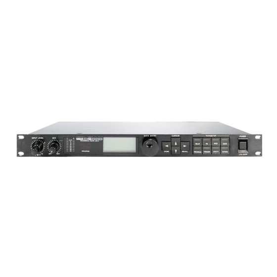
PROFESSIONAL DIGITAL DELAY
OPERATING MANUAL
MANUEL D'UTILISATION
BEDIENUNGSHANDBUCH
INPUT LEVEL
0
-00
+10
DRY
L
R
YDG2030
MIX
L
R
CLIP
PROFESSIONAL DIGITAL DELAY
-6
-12
-18
-24
-30
-36
-42
PROGRAM
WET
DATA ENTRY
CURSOR
DELAY
PROGRAM
TRIGGER
STORE
RECALL
PARAMETER
POWER
FB
MOD
DUCK
UTILITY
BYPASS
ON
OFF
Advertisement
Table of Contents

Related Manuals for Yamaha D5000


Summary of Contents for Yamaha D5000
- Page 1 PROFESSIONAL DIGITAL DELAY OPERATING MANUAL MANUEL D’UTILISATION BEDIENUNGSHANDBUCH INPUT LEVEL CLIP YDG2030 DATA ENTRY PROFESSIONAL DIGITAL DELAY PROGRAM CURSOR PARAMETER POWER DELAY DUCK PROGRAM TRIGGER UTILITY BYPASS STORE RECALL...
- Page 2 This product, when installed as indicated in the instructions contained in this manual, meets FCC requirements. Modifications not expressly approved by Yamaha may void your authority, granted by the FCC, to use the product. 2. IMPORTANT: When connecting this product to accessories and/or another product use only high quality shielded cables.
-
Page 3: Table Of Contents
The front panel ... 4 The back panel ... 5 System structure... 6 Program Select Mode... 7 About the programs of the D5000... 7 Recalling a program ... 7 Storing a program ... 8 Parameter Edit Mode ... 9 Editing a delay program ... 9 Setting the DELAY parameters ... -
Page 4: Introduction
For added flexibility, the D5000 can be controlled by MIDI, especially useful with the FREEZE record and playback effect. Please read this operation manual carefully in order to familiarize yourself with the D5000 and its advanced features – and keep the manual in a safe place for later reference. -
Page 5: Precautions
Strong physical shocks can damage the unit. Handle it with care. Do not open the unit, or attempt repairs or modifications yourself This product contains no user-serviceable parts. Refer all maintenance to qualified Yamaha service personnel. Opening the unit and/or tampering with the internal circuitry will void the warranty. -
Page 6: The Front Panel
12 BYPASS key – The [ BYPASS ] key, when pressed, causes the input signal to bypass the internal circuitry. It has an LED which lights while BYPASS is active. 13 POWER – Press to turn the power ON. The last program will be automatically recalled. D5000 DATA ENTRY STORE... -
Page 7: The Back Panel
MIDI IN Connector – This connector receives data from an external MIDI device. OUTPUT L/R Connectors – These are the analog stereo outputs from the D5000. Both the XLR- type connectors and the TRS phone jacks are electrically balanced output connectors. -
Page 8: System Structure
FREEZE and S&H (sample and hold) programs are accessed using the [ DELAY ] key only. • Utility Mode - Customize the operation of the D5000 by modifying the following parameters: SOFTWARE PROTECT, PARAMETER DISPLAY, FOOT SW (footswitch) FUNCTION, MIDI SETUP, MIDI CONTROLLER, MIDI BULK DUMP, PARAMETER COPY, and REPEAT DELAY (This last parameter is only available when the program type is DUAL or SINGLE). -
Page 9: Program Select Mode
Yamaha ships the D5000 with preset programs that illustrate the features of each of the four types of programs. Refer to the list of preset programs on page 30. The preset programs are stored in program numbers 1 to 00 (100). -
Page 10: Storing A Program
STORE operation by pressing any key other than the [ < ] "STORE" CURSOR key. D5000 If you have made changes to the previous settings without storing them, the unit will additionally display the message "Are you sure?" on the LCD. -
Page 11: Parameter Edit Mode
Parameter Edit Mode The D5000 has four types of effect program. The first two are high-quality, multi-tap digital delays, either DUAL (stereo) or SINGLE (mono). The other two are sampling/playback recorder programs. Editing a delay program To edit a delay program, press one of the PARAMETER keys, [ DELAY ] , [ FB ] , [ MOD ] , or [ DUCK ] . - Page 12 Set the tempo by tapping two beats on the [TRIGGER] key or by pressing two beats with a footswitch connected to the TRIGGER Footswitch Jack on the back panel. The D5000 sets the tempo by counting the interval between the two successive beats.
- Page 13 D/A converters. Set the cutoff frequency for the low pass filter for final output. This filter is also applied to the signal just before the D/A converters. Parameter Edit Mode - 11 L-MONO Delay Delay Delay D5000...
-
Page 14: Adding Feedback
TYP ( A, LVL (0 ~ 100%) D5000 Press the [ DELAY ] key again to select the last display page. Use the [ < ] , [ ^ ] , [ > ] , and [ % ] CURSOR keys to move through the various parameters. -
Page 15: Modulating The Delay
LCD changes from "ON" to "OFF". Select OFF, sine waveform (SIN), triangle waveform (TRI), or auto pan (PAN). When you select SIN or TRI, the D5000 performs frequency modulation on the signal. If you select PAN, the auto... -
Page 16: Ducking/Gating The Delay
Hold and release A short input signal, like the one shown below, would cause the GATE to open (or close in the case D5000 Press the [ DUCK ] key to select DUCK. Use the [ ^ ] and [ % ] CURSOR keys to move through the various parameters. - Page 17 If the DUCK/GATE is continuously triggered by any of the other sources, it may be kept from closing. As the GATE responds to a trigger source and will open for the set HOLD time, a trigger received while the GATE is open will act as a "re-trigger", causing the GATE to remain open. D5000...
-
Page 18: Editing A Sampling/Playback Program
Set the recording method. Press the [ TRIGGER ] key or step on a footswitch MANUAL connected to the TRIGGER Footswitch Jack to put the D5000 in standby mode. Recording will start when you press the key or step on the footswitch again. - Page 19 Not recorded Not recorded When the D5000 is in standby mode, the bar graph at the bottom of the LCD will have the message "REC. READY" displayed on it. During the recording process, the bar graph indicates the current status. Upon completion of the recording, the message "OK" will be displayed on the bar graph.
- Page 20 When the input level is higher than a specified INPUT TRG threshold, the D5000 will playback the data the specified number of times. Select the start point of the playback. For stereo, select a value between 0.00 and 5200.00. For mono, select a value between 0.00 and 10400.00.
- Page 21 * Sound is reversed * Sound is reversed Set the pitch for playback. The D5000 can adjust the pitch by plus or minus two octaves. When you change the pitch, the playback time of the sample is also changed. As the pitch drops, the playback time increases, and when the pitch is increased, the playback time is shortened.
-
Page 22: S&H (Sample And Hold) Program
Fine tune the pitch by 100 cents. Specify the note that will be centre frequency for MIDI Note On messages. The D5000 calculates the pitch change as the difference between the BASE KEY and the note number of the pressed key. - Page 23 Indicates that the S&H function is ready to begin recording. Press the [ TRIGGER ] key or step on the footswitch to begin recording. The D5000 is recording a sample. If the recording time has exceeded the maximum, the earliest sampled data will be overwritten by the latest sampled data.
-
Page 24: Utility Mode
22 - Utility Mode Utility Mode The [ UTILITY ] key allows you to access the system parameters. Each time you press the key, the D5000 cycles to the next command: SOFTWARE PROTECT REPEAT DELAY PARAMETER COPY Until you select one of the other modes, the LED set in the [ UTILITY ] key remains lit. -
Page 25: Parameter Display
When PROGRAM is selected, use this item to set the starting program number. If BYPASS is selected, this parameter does not appear. When PROGRAM is selected, use this item to set the last program number. If BYPASS is selected, this parameter does not appear. Utility Mode - 23 D5000... -
Page 26: Midi Set-Up
If you set the FROM parameter to 75 and the TO parameter to 70, the change is in reverse order: MIDI SET-UP The D5000 has seven MIDI program change tables set in banks "A" to "G". Each table contains a list of MIDI program numbers and the corresponding D5000 effect program. You can customize each table for your requirements. -
Page 27: Midi Controller
MIDI CONTROLLER Each D5000 program (except for Sample and Hold programs) can accept input from two MIDI controllers. These parameters allow you to assign a MIDI controller number to the controller channels of the programs (see page 12). MIDI CONTROLLER parameters... -
Page 28: Parameter Copy
26 - Utility Mode BULK DUMP procedure The D5000 should be correctly connected to an external MIDI device, for example, a MIDI data filer such as the Yamaha MDF2. Set the desired parameters. Make certain that the external MIDI device is ready to receive your data. -
Page 29: Repeat Delay
1 ~ 6 repeats. Set the delay in milliseconds (time interval between repeated sounds), metres, or note length. Set the decay in percentage (level of the last repeated sound). Repeat 2 Repeat 3 Decay=40% TIME(ms) Utility Mode - 27 D5000... -
Page 30: How To Initialize The D5000
Press the [ > ] "RECALL" CURSOR key. The message "Initializing now..." will • momentarily appear on the LCD. Then the D5000 will default to Program Select Mode. WARNING PLEASE BE CERTAIN THAT THIS IS WHAT YOU INTEND TO DO. Any custom programs you have created will be lost when the D5000 is reset to its factory settings. -
Page 31: Specifications
Parameter control (send, receive) Parameter value request Parameter data (receive) USA and Canada 120 V AC, 60 Hz General 230 V AC, 50 Hz 240 V AC, 50 Hz 25 W 480 x 336.4 x 45.2 mm 4.7 kg Specifications - 29 D5000... -
Page 32: Preset Program Library
Gated Loop Sample & Hold Capture Freeze Mono Freeze Stereo Freeze * As shipped from the factory, the program numbers from 56 to 96 contain the same programs as from 1 to 41. D5000 Type Input Mode DUAL delay STEREO Simple delay program with single active tap. -
Page 33: Block Diagram
100 - Block diagram/Schéma de principe/Blockdeagramm Block diagram/Schéma de principe/Blockdeagramm Single D5000 Block Diagram (mono type) Lch INPUT A / D INPUT LEVEL Rch INPUT A / D INPUT LEVEL -20/+4dBm L INPUT R CLIP LEVEL METER MIDI OUT/THRU Stereo... -
Page 34: Dimensions
Dimensions/Abmessungen - 101 Dimensions/Abmessungen W:480 D5000... -
Page 35: Midi Data Format
00100000 00111000 01000001 00110110 00110011 Data Name 01010100 Bank Number 0zzzzzzz Data 0ddddddd 0ddddddd D5000 OMNI, 1~ 16 CH = ? (F0H) (43H) (0nH) n = 0 (channel number1) ~ 15 (channel number 16) (7EH) (02H) (28H) (4CH) ASCII “L”... - Page 36 ASCII “ ” v = 1 r = 0 9 Bytes (F7H) (F0H) (43H) (1nH) n = 0 (channel number1) ~ 15 (channel number 16) (1EH) (03H) 1st byte 2nd byte 8 bytes (F7H) MIDI Data format - 103 D5000...
- Page 37 Sub Status 0010nnnn Format Number 01111110 01001100 01001101 00100000 00100000 00111000 01000001 D5000 BASE KEY NOTE ON (9nH) ON (C1 ~ C6) NOTE OFF (8nH) CONTROL CHANGE (BnH) PROGRAM CHANGE (CnH) BULK DUMP REQUEST (F0H,43H,2nH) BULK DUMP (F0H,43H,0nH) BANK CHANGE (F0H,43H,0nH)
- Page 38 = 0 (channel number1) ~ 15 (channel number 16) (1EH) (03H) 1st byte 2nd byte (F7H) (F0H) (43H) (0nH) n = 0 (channel number1) ~ 15 (channel number 16) (7CH) Condition set-up (00H) (0DH) MIDI Data format - 105 D5000...
- Page 39 When a delay program is loaded, the tempo parameter is set automatically by the timing clock. 2 Active Sensing 11111110 If playback is started with a MIDI Note On message in the FREEZE program and active sensing is interrupted, playback will be stopped. D5000 (4CH) ASCII "L” (4DH) ASCII "M”...
-
Page 40: D5000 Parameter List
OFF. SIN TRI. PAN OFF. SIN TRI. PAN DATE: PROGRAMMER: TYPE: DUAL . SINGLE TEMPO: DUCK TYPE LEVEL SOURCE TARGET HOLD RELEASE THRESHOLD OUTPUT CONTROL ASSIGN comment: DEPTH PHASE D5000 Parameter List - 107 [OFF . ON] OUT LEVEL PARAMETER D5000... -
Page 41: Midi Implementation Chart
:Local ON/OFF | x :All Notes OFF| x |Mes- :Active Sense | x |sages:Reset +-------------------+----------------+----------------+-----------------+ |Note: *1 = For program 1 ~ 128, program number of D5000 is selected. +-----------------------------------------------------------------------+ Mode 1 : OMNI ON, Mode 3 : OMNI OFF, POLY... - Page 42 P.O.Box 1,Hamamatsu,Japan VS10980 R1 1 CR 94 11 500 CR Printed in Japan...