ABB RELION 615 Series Installation Manual
Hide thumbs
Also See for RELION 615 Series:
- Technical manual (1196 pages) ,
- Applications manual (220 pages) ,
- Operation manual (164 pages)
Table of Contents
Advertisement
Quick Links
Advertisement
Table of Contents

Related Manuals for ABB RELION 615 Series


Summary of Contents for ABB RELION 615 Series
- Page 1 — ® RELION PROTECTION AND CONTROL 615 series Installation Manual...
- Page 3 Document ID: 1MRS756375 Issued: 2021-12-21 Revision: T Product version: 5.0 FP1 © Copyright 2021 ABB. All rights reserved...
- Page 4 Copyright This document and parts thereof must not be reproduced or copied without written permission from ABB, and the contents thereof must not be imparted to a third party, nor used for any unauthorized purpose. The software or hardware described in this document is furnished under a license and may be used, copied, or disclosed only in accordance with the terms of such license.
- Page 5 Other than under explicit contractual commitments, in no event shall ABB be responsible or liable for any loss or damage resulting from the use of this manual or the application of the equipment.
- Page 6 Conformity This product complies with following directive and regulations. Directives of the European parliament and of the council: • Electromagnetic compatibility (EMC) Directive 2014/30/EU • Low-voltage Directive 2014/35/EU • RoHS Directive 2011/65/EU UK legislations: • Electromagnetic Compatibility Regulations 2016 • Electrical Equipment (Safety) Regulations 2016 •...
- Page 7 Safety information Dangerous voltages can occur on the connectors, even though the auxiliary voltage has been disconnected. Non-observance can result in death, personal injury or substantial property damage. Only a competent electrician is allowed to carry out the electrical installation. National and local electrical safety regulations must always be followed.
-
Page 8: Table Of Contents
Contents Contents Introduction....................11 This manual............................. 11 Intended audience..........................11 Product documentation........................12 1.3.1 Product documentation set....................12 1.3.2 Document revision history....................12 1.3.3 Related documentation......................13 Symbols and conventions........................13 1.4.1 Symbols........................... 13 1.4.2 Document conventions......................14 Environmental aspects................15 Sustainable development........................15 Disposal of a protection relay ...................... - Page 9 Contents 4.3.7 Rack mounting protection relay and test switch RTXP into 19” equipment frame ..........................38 4.3.8 Rack mounting protection relay into combiflex 19" equipment frame (Type RHGT 19" 4U variant C) ....................39 4.3.9 Mounting lens sensors for an arc protection system ...........42 4.3.10 Replacing a Strömberg SP_J40 series relay by a 615 series IED........43 4.3.11...
- Page 10 Contents Accessories and ordering data.............. 81 Glossary....................83 615 series Installation Manual...
-
Page 11: Introduction
1MRS756375 T Introduction Introduction This manual The installation manual contains instructions on how to install the protection relay. The manual provides procedures for mechanical and electrical installation. The chapters are organized in the chronological order in which the relay should be installed. -
Page 12: Product Documentation
1.3.1 Product documentation set Figure 1: The intended use of documents during the product life cycle Product series- and product-specific manuals can be downloaded from www.abb.com/relion the ABB Web site 1.3.2 Document revision history Document revision/date Product series version History... -
Page 13: Related Documentation
Content updated https:// Download the latest documents from the ABB Web site www.abb.com/mediumvoltage 1.3.3 Related documentation Product series- and product-specific manuals can be downloaded from the ABB http://www.abb.com/substationautomation Web site Symbols and conventions 1.4.1 Symbols The electrical warning icon indicates the presence of a hazard which could result in electrical shock. -
Page 14: Document Conventions
Introduction 1MRS756375 T The caution icon indicates important information or warning related to the concept discussed in the text. It might indicate the presence of a hazard which could result in corruption of software or damage to equipment or property. The information icon alerts the reader of important facts and conditions. -
Page 15: Environmental Aspects
1MRS756375 T Environmental aspects Environmental aspects Sustainable development Sustainability has been taken into account from the beginning of the product design including the pro-environmental manufacturing process, long life time, operation reliability and disposing of the protection relay. The choice of materials and the suppliers have been made according to the EU RoHS directive (2002/95/EC). - Page 16 Environmental aspects 1MRS756375 T Table 2: Materials of the protection relay parts Protection relay Parts Material Case Metallic plates, parts and Steel screws Plastic parts , LCP Electronics plug in module Various Plug-in unit Electronics plug in modules Various Electronics LHMI module Various Plastic parts PC, PBT...
-
Page 17: Unpacking, Inspecting And Storing
1MRS756375 T Unpacking, inspecting and storing Unpacking, inspecting and storing Removing transport packaging Protection relays require careful handling. Examine the delivered products to ensure that they have not been damaged during the transport. Remove the transport packaging carefully without force. Attach the protective film (supplied with the protection relay) on the top side of the unit for the installation phase. -
Page 18: Inspecting Product And Delivery Items
Returning a product damaged in transit If damage has occurred during transport, appropriate actions must be taken against the latest carrier. Please inform the nearest ABB office or representative. Notify ABB immediately if there are any discrepancies in relation to the delivery documents. Storing If the protection relay is stored before installation, it must be done in the original transport packaging in a dry and dust free place. -
Page 19: Mounting
1MRS756375 T Mounting Mounting Checking environmental conditions and mounting space The mechanical and electrical environmental conditions at the installation site must be within the limits described in the technical manual. • Avoid installation in dusty, damp places. Avoid places susceptible to rapid temperature variations, powerful vibrations and shocks, surge voltages of high amplitude and fast rise time, strong induced magnetic fields or similar extreme conditions. - Page 20 Mounting 1MRS756375 T Lift the handle to 90 degrees to release the latching mechanism. The plug-in unit is pushed about 7 mm out of the case and the connectors are separated. Pull the unit out of the case. Figure 2: Detaching a plug-in unit from the case The protection relay features an automatic short-circuit mechanism in the CT connector.
-
Page 21: Installing Plug-In Unit
1MRS756375 T Mounting 4.2.2 Installing plug-in unit The protection relay is constructed in a way that a plug-in unit with voltage- or current-measuring inputs can only be plugged into a corresponding case. This prevents fitting an unsuitable plug-in unit into a wrong case. Before fitting the plug-in unit into the case, check that the unit and the case have the same serial number. - Page 22 Mounting 1MRS756375 T Lift the handle 90 degrees and push the plug-in unit into the case. Figure 4: Installing a plug-in unit into the case 615 series Installation Manual...
- Page 23 1MRS756375 T Mounting Let the handle swing down about 45 degrees. At the same time, push the plug-in unit into the case as far as it goes. Plug-in unit stops at about 7 mm distance from the case. 7 mm Figure 5: Pushing the plug-in unit into the case Turn down the handle to push the plug-in unit into its final position in the case.
-
Page 24: Sealing Plug-In Unit
Mounting 1MRS756375 T 4.2.3 Sealing plug-in unit The front panel of the protection relay has an integrated sealing screw. By default the screw is screwed all the way in and is not used when installing or detaching the plug-in unit. Open the sealing screw about nine turns. -
Page 25: Securing Handle
1MRS756375 T Mounting 4.2.4 Securing handle The front panel of the protection relay has an integrated sealing screw. By default, the screw is screwed all the way in and not used when installing or detaching the plug-in unit. Instead of sealing the plug-in unit, the sealing screw and the spacer supplied with the protection relay can be used for securing the handle in place. -
Page 26: Mounting Protection Relay
Mounting 1MRS756375 T Mounting protection relay 4.3.1 Required tools • T25 Torx screwdriver for mounting the case • T20 Torx screwdriver for connecting the protective earthing Only use adjustable torque screwdrivers. 4.3.2 Flush mounting protection relay All the mounting elements are integrated in the protection relay. Requirements for installation: •... - Page 27 1MRS756375 T Mounting Mount the case to the panel cut-out. 165.5 ±1 mm M5 fixing screws 161.5 ±1 mm Figure 8: Flush mounting a case into a panel cut-out 615 series Installation Manual...
- Page 28 Mounting 1MRS756375 T Tighten the M5 (T25) screws. The allowed range for the fixing screws’ tightening torque is 0.7...1 Figure 9: Flush mounted case, tightening the M5 fixing screws Install the plug-in unit into the case. 615 series Installation Manual...
-
Page 29: Semi-Flush Mounting Protection Relay
1MRS756375 T Mounting 177 mm 153 mm 177 mm 48 mm 164 mm 160 mm 201 mm Figure 10: Flush mounted case and plug-in unit 4.3.3 Semi-flush mounting protection relay A mounting kit is needed for semi-flush mounting the protection relay. In addition to the detailed mounting instructions, the mounting kit includes: •... - Page 30 Mounting 1MRS756375 T Mount the raising frame into the panel cut-out with four M4 screws. 173.5 ±0.3 mm ∅ 5.5 mm 165.5 ±1 mm Panel 161.5 ±1 mm Raising frame 133 ±0.3 mm M4 screw Figure 11: Mounting the raising frame Loosen the four M5 fixing screws in the case to fit the case to the raising frame.
- Page 31 1MRS756375 T Mounting The purpose of the protective film is to prevent debris falling inside the unit while installing electrical wiring. Remove the protective film before energizing the protection relay. 186 mm 103 mm 177 mm 98 mm 201 mm 160 mm Figure 13: Semi-flush mounted protection relay Check the allowed minimum bending radius from the optical cable...
-
Page 32: Semi-Flush Mounting Protection Relay Inclined
Mounting 1MRS756375 T 4.3.4 Semi-flush mounting protection relay inclined A mounting kit is needed for semi-flush mounting the protection relay inclined. In addition to the detailed mounting instructions, the mounting kit includes: • Angle frame • Gasket • Screws Requirements for installation •... -
Page 33: Rack Mounting Protection Relay
1MRS756375 T Mounting 25° 190 mm 221 mm M4 screws 9 mm Gasket 107 mm Angled frame 133 mm Case 230 mm Plug-in unit Figure 15: Protection relay semi-flush mounted inclined 4.3.5 Rack mounting protection relay A mounting kit is needed for rack mounting the protection relay. In addition to the detailed mounting instructions, the 19"... - Page 34 Mounting 1MRS756375 T Mount the case to the panel cut-out. 482.6 mm (19") 177 mm (4U) Figure 16: 19” rack mounting panels Tighten the screws. The allowed range for the fixing screws’ tightening torque is 0.7...1 Install the plug-in unit into the case. 615 series Installation Manual...
-
Page 35: Wall Mounting Protection Relay
1MRS756375 T Mounting Figure 17: Rack mounted protection relay 4.3.6 Wall mounting protection relay A mounting kit is needed for wall mounting the protection relay. In addition to the detailed mounting instructions, the wall mounting kit includes: • Wall mounting frame and rail parts •... - Page 36 Mounting 1MRS756375 T Mount the case between the rails. 430 mm Figure 18: Wall mounting the protection relay Tighten the screws. The allowed range for the fixing screws’ tightening torque is 0.7...1 615 series Installation Manual...
- Page 37 1MRS756375 T Mounting 214 mm 270 mm 177 mm Figure 19: Wall mounted protection relay Minimum of 50 mm space is needed between two kits. When connecting the wires, a wall-mounted protection relay can be pulled out and turned 45° (or 90°) degrees downwards or upwards. •...
-
Page 38: Rack Mounting Protection Relay And Test Switch Rtxp Into 19" Equipment Frame
Mounting 1MRS756375 T 455 mm Figure 20: Wall mounted protection relay in rotated position Minimum of 50 mm space is needed above and below the frame for rotating. 4.3.7 Rack mounting protection relay and test switch RTXP into 19” equipment frame A mounting kit is needed for rack mounting the protection relay into a 19"... - Page 39 1MRS756375 T Mounting Loosen the four M5 fixing screws in the case to fit the case into the panel cut-out. Mount the case to the panel cut-out. Install the optional metallic frame to mount the RTXP 18 or 24 test switch to the panel.
-
Page 40: Rack Mounting Protection Relay Into Combiflex 19" Equipment Frame (Type Rhgt 19" 4U Variant C)
Mounting 1MRS756375 T 4.3.8 Rack mounting protection relay into combiflex 19" equipment frame (Type RHGT 19" 4U variant C) A mounting bracket is needed for rack mounting the protection relay into a combiflex 19" equipment frame, a different bracket is in installation with test switch. - Page 41 1MRS756375 T Mounting Install the plug-in unit into the case. RHGT 19" 4U equipment frame, Mounting bracket variant C, with support frame Tapping screw ST3.5x13 Figure 23: Mounting the protection relay into a 19" combiflex equipment frame Install the optional RTXP 18 or 24 test switch. 615 series Installation Manual...
-
Page 42: Mounting Lens Sensors For An Arc Protection System
Mounting 1MRS756375 T RHGT 19" 4U equipment frame, Mounting bracket for mounting variant C, with support frame with test switch RTXP 18 Tapping screw ST3.5x13 Figure 24: Protection relay and the test switch 4.3.9 Mounting lens sensors for an arc protection system Arc protection is used to detect arc situations in air insulated metal-clad switchgear. -
Page 43: Replacing A Strömberg Sp_J40 Series Relay By A 615 Series Ied
1MRS756375 T Mounting Fit the lens sensor into the hole and fasten it with a self-tapping M3 screw. Alternatively, the lens sensor can be fastened with a cable tie. To do this, secure the cable tie to a suitable point of attachment on the cubicle wall and wrap the cable tie tightly around the sensor. -
Page 44: Replacing Two Strömberg Sp_J3 Series Relays By A 615 Series Ied
Mounting 1MRS756375 T Mount the installation plate to the existing panel cut-out with M5 thread forming screws. Installation plate Torx head screw M5x10 Figure 28: Installation plates for replacing SP_J40 relay Tighten the screws. Mount the new IED. For ordering numbers, see the ordering number table. 615 series Installation Manual... - Page 45 1MRS756375 T Mounting 4.3.11 Replacing two Strömberg SP_J3 series relays by a 615 series IED Make a new panel cut-out to the existing mounting panel according to the dimensional drawing. 155 mm Min. 165.5 mm 15 mm Min. 161.5 mm 196 mm New panel cut-out line Figure 29: New panel cut-out and screw hole dimensions for replacing two...
- Page 46 Mounting 1MRS756375 T Mount the installation plate to the panel cut-out with M5 thread forming screws. Installation plate Torx head screw M5x10 Figure 30: Installation plate for replacing two SP_J3 relays Tighten the screws. Mount the new IED. For ordering numbers, see the ordering number table. 615 series Installation Manual...
-
Page 47: Replacing A Strömberg Sp_J3/J6 Series Relay In 19" Rack By A 615 Series Ied
1MRS756375 T Mounting 4.3.12 Replacing a Strömberg SP_J3/J6 series relay in 19" rack by a 615 series IED Mount the installation plate to the existing panel cut-out with M6 screws and nuts. Use the existing screw holes. 446 mm 460 mm 196 mm 114.5 mm Figure 31: Screw hole and existing panel cut-out dimensions for replacing a... - Page 48 Mounting 1MRS756375 T 4.3.13 Replacing a Strömberg SP_J6 series relay by a 615 series Drill new screw holes (ø4.5 mm) to the panel according to the dimensional drawing. 186 ± 1 mm 196 mm 186 ± 1 mm 196 mm Figure 33: Screw hole and existing panel cut-out dimensions for a SP_J6 series relay 615 series...
- Page 49 1MRS756375 T Mounting Mount the installation plate to the existing panel cut-out with M5 thread forming screws. Installation plate Torx head screw M5x10 Figure 34: Installation plate for replacing SP_J6 relay Tighten the screws. Mount the new IED. For ordering numbers, see the ordering number table. 615 series Installation Manual...
-
Page 50: Replacing Three Bbc S_ Series Relays By A 615 Series Ied
Mounting 1MRS756375 T 4.3.14 Replacing three BBC S_ series relays by a 615 series IED Make a new panel cut-out to the existing mounting panel according to the dimensional drawing. 92 mm 100 mm 234 mm 250 mm Figure 35: Existing panel cut-out and screw hole dimensions for three BBC S_ series relays New panel cut-out line Figure 36: New panel cut-out for replacing BBC S_ series relays... - Page 51 1MRS756375 T Mounting Mount the installation plate to the panel cut-out with M5 screws, nuts and washers. Use the existing screw holes. Installation plate Hexagon nut M5 Torx head screw M5x16 Spring washer Figure 37: Installation plate for replacing three BBC S_ relays Tighten the screws.
-
Page 52: Replacing A Spa 300 Series Relay By A 615 Series Ied
Mounting 1MRS756375 T 4.3.15 Replacing a SPA 300 series relay by a 615 series IED Make a new panel cut-out to the existing mounting panel according to the dimensional drawing. Min. 186 mm 176 mm 161.5 ± 1 mm 7 mm 224 mm Figure 38: New panel cut-out and screw hole dimensions for replacing a SPA 300 series relay... -
Page 53: Replacing A Spa 300 Series Relay In 19" Rack By A 615 Series Ied
1MRS756375 T Mounting Mount the installation plate to the panel cut-out with M5 thread forming screws. Installation plate Torx head screw M5x10 Figure 39: Installation plate for replacing SPA 300 relay Tighten the screws. Mount the new IED. Use a raising frame if needed. For ordering numbers, see the ordering number table. -
Page 54: Connecting
Connecting 1MRS756375 T Connecting Required tools Only use a screwdriver and insert bits for Phillips (PH 1) cross-recessed head screws (M3.5) when handling CT/ VT terminals (X120) of screw-compression type. Max. ø5.5 mm Max. ø5 mm Figure 40: Screwdriver for CT/VT terminals of screw-compression type Min. -
Page 55: Connecting Protective Earthing
1MRS756375 T Connecting Connecting protective earthing The earth lead must be at least 6.0 mm . If the earth lead is long, the cross section of the wire must be increased. Use fine copper wire as the earth lead. Loosen the protective earth screw (T20) to connect a separate earth protection lead. -
Page 56: Connecting Analog Signals
Connecting 1MRS756375 T Tighten the protective earth screw. Support the earth lead so that it cannot break or weaken. Be aware of the mechanical, chemical and electrochemical environment. Connecting analog signals A connection diagram is needed to connect the analog signals. When using the ring-lug type for CT/VT terminals, follow these steps. - Page 57 1MRS756375 T Connecting AIM0003 X130 mA 1 RTD1 RTD2 60 - 210V U12B/UoB/Not in use 60 - 210V 60 - 210V 60 - 210V 60 - 210V Figure 43: Example of AIM0003 card variant (5 U, 2 RTD + 1 mA channel) Figure 44: Example of AIM0004 card variant (4 I + 3 U with 1/5 A Io channel) 615 series Installation Manual...
- Page 58 Connecting 1MRS756375 T AIM0005 Figure 45: Example of AIM0005 card variant (7 I with 1/5 A Io channel) AIM0006 U12B/UoB/Not in use Figure 46: Example of AIM0006 card variant (5 U) 615 series Installation Manual...
- Page 59 1MRS756375 T Connecting Figure 47: Example of AIM0013 card variant (4 I + 3 U with 0.2/1 A Io channel) AIM0015 X120 1/5A IL1B 1/5A IL2B 1/5A IL3B 1/5A 1/5A 1/5A 0.2/1A Figure 48: Example of AIM0015 card variant, (7 I with 0.2/1 A Io channel) 615 series Installation Manual...
- Page 60 Connecting 1MRS756375 T AIM0016 Figure 49: Example of AIM0016 card variant (4 I with 1/5 A Io channel) AIM0017 Figure 50: Example of AIM0017 card variant (4 I with 0.2/1 A Io channel) 615 series Installation Manual...
- Page 61 1MRS756375 T Connecting Figure 51: Example of AIM0018 card variant (4 I + Uo with 1/5 A Io channel) Figure 52: Example of AIM0019 card variant (4 I + Uo with 0.2/1 A Io channel) 615 series Installation Manual...
- Page 62 Connecting 1MRS756375 T SIM0002 X130 0.2/1A X131 X132 X133 Figure 53: Example of SIM0002 card variant (4I+3U with 0.2/1 A Io channel) SIM0005 X130 0.2/1A X131 IL1/A X132 IL2/B X133 IL3/C Figure 54: Example of SIM0005 card variant (4I+3U with 0.2/1 A Io channel). Including red sensor connectors.
-
Page 63: Connecting Rtd And Ma Inputs
1MRS756375 T Connecting 5.4.2 Connecting RTD and mA inputs • Connect the wires from the transducers to the correct device according to the connection diagram. Each terminal for RTDs and mA inputs is dimensioned for one 0.5...2.5 mm wire or for two 0.5...1.0 mm wires. -
Page 64: Shielding Rtd/Ma Instrument Cables
Connecting 1MRS756375 T 5.4.4 Shielding RTD/mA instrument cables The RTD/mA inputs are connected by screened cables (1 mm /AWG18), for example, Unitronic 300S (formerly Unitronic 300CY), manufactured by LAPP Group. Other manufacturers' cables with similar technical features can also be used. - Page 65 1MRS756375 T Connecting Heat shrinkable cap Drain wire Figure 56: Screened cable Connect the functional earthing wires (drain wires) to the protection relay's body via a connection flange (2RCA036978A0001) to separate them from the protective earthing conductor. Drain wires Figure 57: Connection of drain wires Cannot be used when the protection relay is mounted with the Combiflex 19"...
-
Page 66: Connecting Binary Signals
Connecting 1MRS756375 T Connecting binary signals • Connect the wires for the binary signals to the correct device according to the connection diagram. Each terminal for binary input and output signal is dimensioned for one 0.5...2.5 mm wire or for two 0.5...1.0 mm wires. - Page 67 1MRS756375 T Connecting Figure 59: Example of BIO0006 card variant (6 BI + 3 BO) 615 series Installation Manual...
- Page 68 Connecting 1MRS756375 T BIO0007 X110 BI 1 BI 2 BI 3 BI 4 BI 5 BI 6 BI 7 BI 8 N.C. N.C. N.C. N.C. HSO1 N.C. N.C. HSO2 N.C. N.C. HSO3 Figure 60: Example of BIO0007 card variant (8 BI + 3 BO) 615 series Installation Manual...
-
Page 69: Connecting Power Supply
1MRS756375 T Connecting Connecting power supply The permitted auxiliary voltage range of the protection relay is marked on top of the protection relay's LHMI. • Connect the protection relay's auxiliary voltage to terminals X100-1 and X100-2. • Connect the positive lead to terminal X100-1. Figure 61: Connecting auxiliary voltage Connecting communication •... -
Page 70: Energizing Protection Relay
During the start-up, indications and self test procedures are shown in a certain order. Green Ready LED starts to flash. LCD lights up and ABB logo is displayed. LCD test patterns are displayed and all the LEDs are lit for a short period. -
Page 71: Removing, Repairing And Exchanging
Internet by following the links within ABB Service Guide or via ABB Product Guide from the product specific Service & Support sheet. Checking protection relay information The protection relay information includes detailed information about the device, such as version and serial number. The protection relay information is shown on the display for a few seconds when the device starts up. -
Page 72: Removing Protection Relay
Figure 63: Loosening the M5 screws Detach the case from the panel cut-out. Sending protection relay for repair • In case of product problems, contact the nearest ABB office or representative for consultation and instructions. Exchanging protection relay • To exchange the protection relay with another identical unit, remove the protection relay and install the new one. - Page 73 1MRS756375 T Removing, repairing and exchanging • To exchange a protection relay to a different unit, change the case and connect the wires. • When replacing only the plug-in unit for maximum system availability, check that the order number of the case and the spare plug-in unit are equal to ensure the type compatibility.
-
Page 74: Technical Data
Technical data 1MRS756375 T Technical data 615 series Installation Manual... -
Page 75: Case And Hmi Display Variants
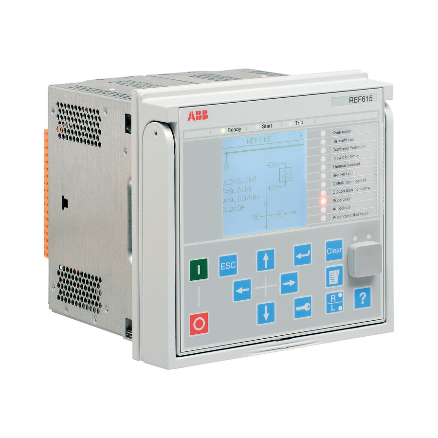
1MRS756375 T Technical data Case and HMI display variants 7.1.1 Front side of the protection relay Figure 64: Small display (IEC variant) 615 series Installation Manual... - Page 76 Technical data 1MRS756375 T Figure 65: Small display (CN variant) 615 series Installation Manual...
- Page 77 1MRS756375 T Technical data Figure 66: Large display (IEC variant) 615 series Installation Manual...
- Page 78 Technical data 1MRS756375 T Figure 67: Large display (CN variant) Table 4: Small display Character size Rows in the view Characters per row Small, mono-spaced (6 × 12 pixels) Large, variable width (13 × 14 pixels) 8 or more Table 5: Large display Character size Rows in the view Characters per row...
-
Page 79: Rear Side Of The Protection Relay
1MRS756375 T Technical data 7.1.2 Rear side of the protection relay Figure 68: Rear view of a 615 series protection relay with communication module Dimensions Table 6: Dimensions Description Value Width Frame 177 mm Case 164 mm Height Frame 177 mm (4U) Case 160 mm Depth... -
Page 80: Degree Of Protection Of Flush-Mounted Protection Relay
Technical data 1MRS756375 T Degree of protection of flush-mounted protection relay Table 7: Degree of protection of flush-mounted protection relay Description Value Front side IP 54 Rear side, connection terminals IP 20 615 series Installation Manual... - Page 81 1MRS756375 T Accessories and ordering data Accessories and ordering data Table 8: Cables Item Order number Optical sensor for arc protection, cable length 1.5 m 1MRS120534-1.5 Optical sensor for arc protection, cable length 3.0 m 1MRS120534-3 Optical sensor for arc protection, cable length 5.0 m 1MRS120534-5 Optical sensor for arc protection, cable length 7.0 m 1MRS120534-7...
- Page 82 Accessories and ordering data 1MRS756375 T Item Order number Replacement kit for a Strömberg SP_J6 series relay 2RCA027881A0001 Replacement kit for three BBC S_ series relays 2RCA027882A0001 Replacement kit for a SPA 300 series relay 2RCA027885A0001 615 series Installation Manual...
- Page 83 1MRS756375 T Glossary Glossary Analog input module BI/O Binary input/output Binary input and output Current transformer Electromagnetic compatibility Hardware International Electrotechnical Commission Liquid crystal display Liquid crystal polymer Light-emitting diode LHMI Local human-machine interface Polyamide Polybutylene terephthalate 1. Personal computer 2.
- Page 84 — ABB Distribution Solutions Digital Substation Products P.O. Box 699 FI-65101 VAASA, Finland Phone +358 10 22 11 www.abb.com/mediumvoltage www.abb.com/relion www.abb.com/substationautomation © Copyright 2022 ABB. All rights reserved.