Table of Contents
Advertisement
Quick Links
Advertisement
Table of Contents

Related Manuals for Verizon TR2


Summary of Contents for Verizon TR2
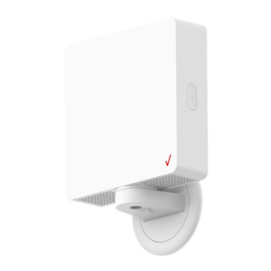
- Page 1 Verizon 5G Extender User Guide Version 3...
- Page 2 Federal Communication Commission Interference Statement This device complies with Part 15 of the FCC Rules. Operation is subject to the following two conditions: (1) This device may not cause harmful interference, and (2) this device must accept any interference received, including interference that may cause undesired operation. This equipment has been tested and found to comply with the limits for a Class B digital device, pursuant to Part 15 of the FCC Rules.
- Page 3 RF Exposure Statement To comply with FCC RF exposure compliance requirements, the antenna used for this transmitter must be installed to provide a separation distance of at least 20 cm from all persons and must not be co-located or operating in conjunction with any other antenna or transmitter.
-
Page 4: Table Of Contents
Table of Contents Chapter 1 Introduction .......................... 1 1.1 Unboxing Information ........................ 1 1.2 Front Panel ..........................2 1.3 Back Panel ..........................4 1.4 Bottom Panel ..........................5 1.5 Side Panel ..........................6 1.6 Mounting Bracket ........................7 Chapter 2 Installing the 5G Extender ....................9 2.1 Preparations for mounting of the 5G Extender ................. -
Page 5: Chapter 1 Introduction
Chapter 1 Introduction This chapter includes a list of items included with the TR2 5G Extender and a description of the user interface and ports on the device. Unboxing Information Inside the product package for the TR2 5G Extender, you should find the following items: •... -
Page 6: Front Panel
Front Panel An LED indicator is located in the top-left corner of the Extender’s front panel. LED Light Guide Device Status Description LED Status The Extender is powered and in the process Booting up Blinking: White of booting up. The Extender is ready to be paired with the Ready to pair Blinking: Blue App. - Page 7 Device Status Description LED Status Paired: Poor The signal strength from the 5G nodes is Solid: Yellow Signal poor. Paired: No/bad There is no signal from the 5G nodes. Solid: Red Signal Regular usage The Extender is working normally. An error has occurred (ex. pairing/firmware Error Blinking: Red issue)
-
Page 8: Back Panel
Back Panel 1. Product label and QR code Scan the QR code on this label with the Installer app to enable the receiver to establish a connection with the Extender. 2. Mounting head The mounting head fits into the installation slot on the mounting bracket. -
Page 9: Bottom Panel
Bottom Panel 1. DC jack Plug the AC adapter into this jack to power the Extender. 2. USB Type-C port This port is used for diagnostic purposes. -
Page 10: Side Panel
Side Panel 1. Scan button Use this button to scan for 5G signals from 5G nodes located outdoors. You may also press and hold this button for 20 seconds to switch between regular mode and installation mode. In addition, pressing and holding this button for more than 40 seconds triggers the factory reset process. 2. -
Page 11: Mounting Bracket
Mounting Bracket 1. Mounting holes Wall screws are screwed through these mounting holes during wall installation. 2. Bracket cover This cover is attached to the top of the bracket’s base. Remove the cover before attaching the mounting bracket to a wall. 3. - Page 12 4. Mounting plate During window installation the mounting plate is attached to the window, providing an attachment point for the Extender. 5. Hole for AC adapter This hole enables the cable from the AC adapter to connect to the DC jack when the Extender is installed on the mounting bracket.
-
Page 13: Chapter 2 Installing The 5G Extender
Chapter 2 Installing the 5G Extender Preparations for mounting of the 5G Extender Step 1. Attach the bracket to the Extender, and connect the AC adapter to the Extender's DC jack. Step 2. The LED indicator will start blinking white. Wait 90 seconds; the LED will start flashing blue once boot up is complete. - Page 14 Step 4. Use the 5G Extender App to scan the QR code on the back of the Extender to execute pairing. Step 5. The LED will turn solid blue after pairing is successful. Step 6. Use the 5G Extender App to apply the 5G SSB information to the Extender. Step 7.
-
Page 15: Window Installation
Step 8. Press the scan button to start signal scanning. Step 9. After 10 seconds, the LED will change to one of the following statuses: Good signal: Solid green Poor signal: Solid yellow No/bad signal: Solid red Note: The LED will revert to solid blue after 20 seconds. - Page 16 Step 1. Use window wipes to clean the installation location. Note: Ensure glass is clean and completely dry. Step 2. Remove the mounting plate from the box and read the instructions carefully. Step 3. Peel off the protective backing from the Gecko adhesive pad on the mounting plate. Affix the mounting plate onto the window in the direction indicated by the arrow on the plate.
- Page 17 Step 5. Attach the bracket of the 5G Extender to the mounting plate by aligning it over the top of the hook on the mounting plate, then sliding it down until it latches onto the hook. Step 6. Adjust the angle of your 5G Extender. Once you find the optimal position, turn the locking tab on the 5G Extender to the locked position.
- Page 18 Step 9. Use cable clips and cable spooler to organize cables. Step 10. If necessary, install a window wedge to prevent sliding windows from colliding with the installed Extender.
-
Page 19: Bracket Removal (Window)
Bracket Removal (Window) Step 1. Unplug the power cable and turn the locking tab on the bottom of the bracket to the unlocked position. Step 2. Remove the Extender. Step 3. Press down on the tab of the mounting plate, then slide the bracket upwards until it detaches from the plate. -
Page 20: Wall Installation
Wall Installation Step 1. Find a location with a good signal and mark the location. Step 2. Remove the bracket base cover. Step 3. Place the bracket on the wall and mark the pilot hole locations. Step 4. Screw the wall screws into anchors. - Page 21 Step 5. Put the bracket cover back in place. Step 6. Install the Extender into the bracket and connect the AC adapter to the Extender's DC jack. Step 7. Press the scan button to confirm the signal. Step 8. Use the 5G Extender App to change the operation mode to regular.
- Page 22 Step 9. Turn the locking tab on the bottom of the bracket to the locked position.
-
Page 23: Chapter 3 Product Specifications
Chapter 3 Product Specifications Hardware Specifications • Support Frequency Bands: n261: 27.5–28.35 GHz n260: Full band LTE: B4 and B13 • Separated TX & RX antenna arrays • Antenna array - 32 elements at 28 GHz/39 GHz donor side - 2 antenna panels at relay side, each has 4/4 elements at 28 GHz/39 GHz •... - Page 24 Use of another adaptor could result in damage to the unit. The following power adaptor is qualified for use with this Verizon 5G Extender: The unit must be powered by DELTA ELECTRONICS, model ADP-48GR BA; 12V, 4A, 48W...