Table of Contents
Advertisement
Quick Links
Advertisement
Table of Contents

Summary of Contents for Vega VEGADIS 371 Ex
- Page 1 Operating Instruction VEGADIS 371 Ex 16.85 VEGADIS 371 Ex 8888...
-
Page 2: Table Of Contents
5.2 Fault signals ..................16 Safety information The described module must only be installed and operated as described in this operating instruction. Please note that other action can cause damage for which VEGA does not take responsibility. VEGADIS 371 Ex... -
Page 3: Product Description
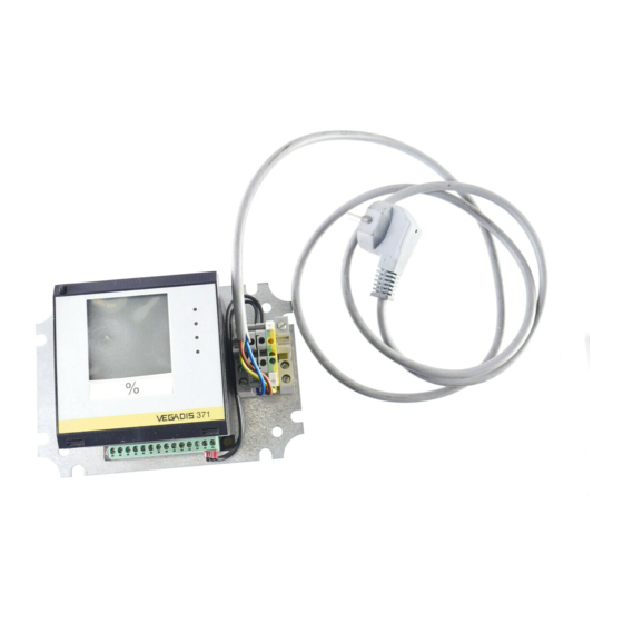
Product description 1 Product description 1.1 Function and configuration 1.3 Approvals VEGADIS 371 Ex is a digital indicating instrument with VEGADIS 371 Ex (appropriate apparatus) is available integral level switches and current output for panel, with the following approval: surface or rail mounting with LC-display for digital and Explosion protection quasianalogue demonstration. -
Page 4: Technical Data
Indication of switching condition LED lights - relay energized LED off - relay deenergized Digital indication Zero point (4 mA or 0 V) -9999 … 9999 Final point (20 mA or 10 V) -9999 … 9999 Decimal point individually selectable VEGADIS 371 Ex... -
Page 5: Mounting
• Insert VEGADIS 371 from the front into the front snap-in. panel (E). • Push the terminal strap (G) from the back to the pin (H) and pull with the knurled nut (I) against the front panel (E). Front panel cut-out VEGADIS 371 Ex... -
Page 6: Electrical Connection
4 ... 20 mA Sensor Voltage supply Passive operation (I 4 ... 20 mA output Sensor Signal conditioning instrument VEGAMET Voltage supply 1) Active or passive operation selectable with slide switch. See “4.1 Indicating and adjustment elements“ VEGADIS 371 Ex... -
Page 7: Sensor Connection Ex-Area
Note: When using VEGADIS 371 the connection of an ia- safety barrier type 145 is not possible. For the use on sensors in hazardous areas, use VEGADIS 371 Ex. VEGADIS 371 Ex must be generally mounted outside hazardous areas. Active operation (I... -
Page 8: Terminal Coordination
Meas. data input blue Ex-separating chamber must be plugged to the terminals of the sensor input (terminals 1 and 2) on VEGADIS 371 Ex, to ensure the required distance (50 mm). • Place the Ex-separating chamber acc. to the figure... -
Page 9: Set-Up
On the housing a shackle (6) is provided for designation. Here you can insert one of the supplied labels. VEGADIS 371 Ex... - Page 10 When you are in menu stage 2, certificate of VEGADIS 371 Ex. the "VEGA“-logo flashes on the display. Push again both keys to return to menu stage 1. After approx. 10 minutes the indication changes automatically to menu stage 1.
-
Page 11: Adjustment
(3 and 4) you can modify the value of the indication. For the given example set the digital indication (8) to the value 90,0 (90,0 %). Hence the internal relay 1 switches on when this value is reached. VEGADIS 371 Ex... - Page 12 The measuring range is not modified, but completely shifted. • Set the rotating switch (7) to position 0 (OPERATE). All adjusted values are transferred to an EEPROM- memory and saved. They remain there even in case of a probable voltage loss. VEGADIS 371 Ex...
- Page 13 € Set the rotating switch to position 3 (pump dependent on the working time. VEGADIS 371 Ex changeover function relay 2) selects for switch on the relay with the shortest €...
-
Page 14: Mounting Of The Relay Modules
When you want to retrofit even in case of power failure. VEGADIS 371 Ex, send the instrument to VEGA. With two relay modules totally 4 output relays are available. The working time is indicated in hours. The max. -
Page 15: Reset
(100) - Decimal point (1. position) - Integration time (0 s) - Offset correction (0 μA) - Current output (4 … 20 mA) Menu stage 2 - Pump changeover function (OFF) - Working time indication (0 hours) VEGADIS 371 Ex... -
Page 16: Diagnosis
Change to menu stage 1. Check the switching function of relay 1. Set all relays which are used for pump changeover function to the same switching function like relay 1 or deactivate the pump changeover function for these relays. VEGADIS 371 Ex... - Page 17 Notes VEGADIS 371 Ex...
- Page 18 Notes VEGADIS 371 Ex...
- Page 19 Notes VEGADIS 371 Ex...
- Page 20 VEGA Grieshaber KG Am Hohenstein 113 D-77761 Schiltach Phone (0 78 36) 50 - 0 Fax (0 78 36) 50 - 201 e-mail info@de.vega.com ISO 9001 The statements on types, application, use and operating conditions of the sensors and processing systems correspond to the actual knowledge at the date of printing.


Need help?
Do you have a question about the VEGADIS 371 Ex and is the answer not in the manual?
Questions and answers