Vega POINTRAC 31 Operating Instructions Manual
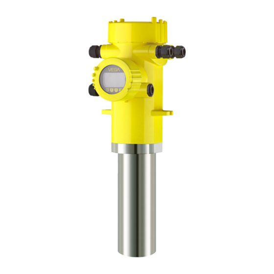
Radiation-based sensor for level
detection
Hide thumbs
Also See for POINTRAC 31:
- Operating instructions manual (68 pages) ,
- Operating instructions manual (68 pages) ,
- Operating instructions manual (64 pages)
Table of Contents
Advertisement
Advertisement
Table of Contents

Related Manuals for Vega POINTRAC 31


Summary of Contents for Vega POINTRAC 31
-
Page 1: Operating Instructions
Tel: +44 (0)191 490 1547 Fax: +44 (0)191 477 5371 Email: northernsales@thorneandderrick.co.uk Website: www.heattracing.co.uk www.thorneanderrick.co.uk Operating Instructions Radiation-based sensor for level detection POINTRAC 31 8/16 mA/HART - four-wire Document ID: 39411... -
Page 2: Table Of Contents
Diagnostics and service Maintenance ........................37 Status messages ......................37 Rectify faults ........................40 Exchanging the electronics module ................41 Software update ......................42 How to proceed in case of repair ..................42 10 Dismounting POINTRAC 31 • 8/16 mA/HART - four-wire... - Page 3 11.2 Dimensions ........................48 Safety instructions for Ex areas Please note the Ex-specific safety information for installation and op- eration in Ex areas. These safety instructions are part of the operating instructions manual and come with the Ex-approved instruments. Editing status: 2013-04-29 POINTRAC 31 • 8/16 mA/HART - four-wire...
-
Page 4: About This Document
Action This arrow indicates a single action. Sequence Numbers set in front indicate successive steps in a procedure. Battery disposal This symbol indicates special information about the disposal of bat- teries and accumulators. POINTRAC 31 • 8/16 mA/HART - four-wire... -
Page 5: For Your Safety
During work on and with the device the required personal protective equipment must always be worn. Appropriate use The POINTRAC 31 is a sensor for level detection. You can find detailed information on the application range in chapter "Product description". Operational reliability is ensured only if the instrument is properly used according to the specifications in the operating instructions manual as well as possible supplementary instructions. -
Page 6: Ce Conformity
That is why we have introduced an environment management system with the goal of continuously improving company environmental pro- tection. The environment management system is certified according to DIN EN ISO 14001. Please help us fulfill this obligation by observing the environmental instructions in this manual: • Chapter "Packaging, transport and storage" • Chapter "Disposal" POINTRAC 31 • 8/16 mA/HART - four-wire... -
Page 7: Product Description
Operating instructions at the time of shipment (PDF) • Order-specific sensor data for an electronics exchange (XML) • Test certificate "Measuring Accuracy" (PDF) For this purpose, move to www.vega.com and "VEGA Tools". As an alternative, you have access to these data via your Smart- phone: • Download the Smartphone-App "VEGA Tools" from the "Apple App Store "... -
Page 8: Principle Of Operation
When the intensity of the radiation drops below a defined value, e.g. due to damping, then the POINTRAC 31 switches. The measuring principle has proven itself well under extreme conditions because it measures contactlessly from outside through the vessel wall. The measuring system ensures maximum safety, reliability and plant availability independent of the medium and its properties. -
Page 9: Accessories And Replacement Parts
GADIS 81" (Document-ID 43814). External indicating unit The VEGADIS 62 is suitable for measured value indication of sensors. It is looped into the 4 … 20 mA/HART signal cable. You can find further information in the operating instructions "VE- GADIS 62" (Document-ID 36469). Electronics module The electronics module PT30E.XX is a replacement part for radiation- based sensors POINTRAC 31. The electronics module can only be exchanged by VEGA service technician. POINTRAC 31 • 8/16 mA/HART - four-wire... -
Page 10: Corresponding Source Container
The local dose rate of the radiation decreases in proportion to the square of the distance to the radiation source. Radiation safety officer The plant operator must appoint a radiation safety officer with the necessary expert knowledge. He is responsible that the radiation protection ordinance is maintained and that all radiation protection measures are implemented. POINTRAC 31 • 8/16 mA/HART - four-wire... - Page 11 (in Ger- many, for example, the radiation protection ordinance). We are at your disposal for further information concerning radiation protection and regulations in other countries. POINTRAC 31 • 8/16 mA/HART - four-wire...
-
Page 12: Mounting
Prior to setup you have to replace these protective caps with ap- proved cable glands or close the openings with suitable blind plugs. The suitable cable glands and blind plugs come with the instrument. POINTRAC 31 • 8/16 mA/HART - four-wire... -
Page 13: Mounting Instructions
Fasten the sensor in such a way that it cannot fall out of the holder. If necessary, provide the sensor with a support from below. Mount the source container and POINTRAC 31 as close as possible to the vessel. If there are gaps, secure the area with a safety fence... - Page 14 Sensor orientation Level detection - max. detection The POINTRAC 31 is suitable for level detection in liquids or bulk solids. It is mounted at the height of the requested switching point. Fig. 4: POINTRAC 31 as max. level detection (uncovered) Level detection - min.
- Page 15 4 Mounting Bulk solids with low density Fig. 6: POINTRAC 31 as level detection (top view) POINTRAC 31 lends itself well for level detection of bulk solids with low density. Mount the instrument horizontally at the height of the requested switching point. Mount the source container VEGASOURCE displaced by 90° in order to get the widest possible radiation angle.
-
Page 16: Connecting To Power Supply
In the sensor, the screen must be connected directly to the internal ground terminal. The ground terminal on the outside of the housing must be connected to the potential equalisa- tion (low impedance). POINTRAC 31 • 8/16 mA/HART - four-wire... - Page 17 3. Remove approx. 10 cm (4 in) of the cable mantle, strip approx. 1 cm (0.4 in) of insulation from the ends of the individual wires 4. Insert the cable into the sensor through the cable entry POINTRAC 31 • 8/16 mA/HART - four-wire...
- Page 18 10. Screw the housing cover back on The electrical connection is hence finished. Information: The terminal blocks are pluggable and can be detached from the electronics. For this purpose loosen the two lateral locking levers of POINTRAC 31 • 8/16 mA/HART - four-wire...
-
Page 19: Connection
Fig. 9: Adjustment and connection compartment with non-Ex instruments and instruments with non-intrinsically safe current output Terminals for the external display and adjustment unit Contact pins for the display and adjustment module or interface adapter MGC = Multi Gauge Communication POINTRAC 31 • 8/16 mA/HART - four-wire... - Page 20 (not with versions with Ex-d approval) Contact pins for the display and adjustment module or interface adapter Terminals for the external display and adjustment unit Ground terminal MGC = Multi Gauge Communication POINTRAC 31 • 8/16 mA/HART - four-wire...
-
Page 21: Set Up With The Display And Adjustment Module
The display and adjustment module is powered by the sensor, an ad- ditional connection is not necessary. Fig. 12: Insert display and adjustment module Note: If you intend to retrofit the instrument with a display and adjustment module for continuous measured value indication, a higher cover with an inspection glass is required. POINTRAC 31 • 8/16 mA/HART - four-wire... -
Page 22: Adjustment System
[OK] will not be saved. Parameter adjustment Through the parameter adjustment the instrument is adapted to the application conditions. The parameter adjustment is carried out via an adjustment menu. Main menu The main menu is divided into five sections with the following func- tions: POINTRAC 31 • 8/16 mA/HART - four-wire... - Page 23 This parameter is described in the operating instructions manual "Display and adjustment module". Setup/Isotope In this menu item you can adjust the POINTRAC 31 to the integrated isotope in the source container. For this purpose, check which isotope is integrated in the source container. You can find this information on the type label of the source...
- Page 24 "X-ray alarm" or "Real value correction". X-ray alarm The radiation of external radiation sources can influence the measur- ing result of continuously measuring, radiation-based sensors. You can also use the POINTRAC 31 as a Slave instrument for detec- tion against X-ray alarm. Hence an alarm can be triggered. For this function you require PACTware with the respective DTM. Real value correction You can also use the POINTRAC 31 as a Slave instrument for detection of a defined level. Hence you can automatically correct the...
- Page 25 (single point adjustment" as adjustment mode (Setup/Adjustment mode). adjustment) In this menu item you determine the point at which the POINTRAC 31 should switch in uncovered status. Empty the vessel until the sensor is uncovered. For this enter the requested pulse rate manually or let the rate be determined by POINTRAC 31.
- Page 26 Enter the requested pulse rate manually or let the rate be determined by POINTRAC 31. Automatic determination of the pulse rate should be given preference. You can enter the adjustment point (ct/s) manually. You can let the adjustment point be determined by POINTRAC 31. POINTRAC 31 • 8/16 mA/HART - four-wire...
- Page 27 POINTRAC 31. Automatic determination of the pulse rate should be given preference. You can enter the adjustment point (ct/s) manually. You can let the adjustment point be determined by POINTRAC 31. Setup/Current output In this menu item you can select the switching behaviour of the sen- mode sor.
- Page 28 If you have carried out a single point adjustment, this is the entered value. With a double point adjustment, this is the calculated value. POINTRAC 31 • 8/16 mA/HART - four-wire...
- Page 29 Pulse rate of the sensor Current output Switching function of the relay Information: The simulation is automatically terminated 10 minutes after the last press of a key. Diagnosis/Calculated The sensor calculates a suitable integration time automatically. damping POINTRAC 31 • 8/16 mA/HART - four-wire...
- Page 30 The following table shows the default values of the instrument. The values apply for the application "Level". First of all you have to select the application. Depending on the instrument version, not all menu items may be available or they may be differently assigned: POINTRAC 31 • 8/16 mA/HART - four-wire...
- Page 31 • Write parameter adjustment data from the display and adjustment module into the sensor This parameter is described in the operating instructions manual "Display and adjustment module". Info In this menu you will find the following menu items: Info POINTRAC 31 • 8/16 mA/HART - four-wire...
-
Page 32: Saving The Parameter Adjustment Data
If it is necessary to exchange a sensor, the display and adjustment module is inserted into the replacement instrument and the data are likewise written into the sensor via the menu item "Copy sensor data". POINTRAC 31 • 8/16 mA/HART - four-wire... -
Page 33: Setup With Pactware
Fig. 15: Connecting the PC via HART to the signal cable POINTRAC 31 2 HART resistance 250 Ω (optional depending on processing) Connection cable with 2 mm pins and terminals Processing system/PLC/Voltage supply Voltage supply Necessary components: • POINTRAC 31 • PC with PACTware and suitable VEGA DTM POINTRAC 31 • 8/16 mA/HART - four-wire... -
Page 34: Parameter Adjustment With Pactware
Further setup steps are described in the operating instructions manu- al "DTM Collection/PACTware" attached to each DTM Collection and which can also be downloaded from the Internet. Detailed descrip- tions are available in the online help of PACTware and the DTMs. POINTRAC 31 • 8/16 mA/HART - four-wire... -
Page 35: Saving The Parameter Adjustment Data
The standard version is available as a download under www.vega. com/downloads and "Software". The full version is available on CD from the agency serving you. -
Page 36: Set Up With Other Systems
DD adjustment programs such as, for example, AMS™ and PDM. The files can be downloaded at www.vega.com/downloads under "Software". Field Communicator 375, 475 Device descriptions for the instrument are available as EDD for pa- rameter adjustment with the Field Communicator 375 or 475. POINTRAC 31 • 8/16 mA/HART - four-wire... -
Page 37: Diagnostics And Service
PACTware/DTM or EDD. Out of specification: The measured value is unstable because the instrument specification is exceeded (e.g. electronics temperature). This status message is inactive by default. It can be activated by the user via PACTware/DTM or EDD. Maintenance: Due to external influences, the instrument function is limited. The measurement is affected, but the measured value is POINTRAC 31 • 8/16 mA/HART - four-wire... - Page 38 – Error in the internal instru- – Carry out a reset ment communication – Exchanging the electronics EPROM data error F036 – Error during software – Repeat software update update – Exchanging the electronics Faulty pro- gram memory POINTRAC 31 • 8/16 mA/HART - four-wire...
- Page 39 Function check The following table shows the error codes and text messages in the status message "Function check" and provides information on causes as well as corrective measures. POINTRAC 31 • 8/16 mA/HART - four-wire...
-
Page 40: Rectify Faults
Treatment of measurement errors Further comprehensive diagnostics options offer a PC with the soft- ware PACTware and the suitable DTM. In many cases, the reasons can be determined in this way and faults can be rectified. Check output signal The following table describes possible faults that may not generate an error message: POINTRAC 31 • 8/16 mA/HART - four-wire... -
Page 41: Exchanging The Electronics Module
The new electronics module must be loaded with the default settings of the sensor. These are the options: • In the factory • Or on site by the user POINTRAC 31 • 8/16 mA/HART - four-wire... -
Page 42: Software Update
• Attach the completed form and, if need be, also a safety data sheet outside on the packaging • Please ask the agency serving you for the address of your return shipment. You can find the competent agency on our website www.vega.com. POINTRAC 31 • 8/16 mA/HART - four-wire... -
Page 43: Dismounting
Pass the instrument directly on to a spe- cialised recycling company and do not use the municipal collecting points. These may be used only for privately used products according to the WEEE directive. POINTRAC 31 • 8/16 mA/HART - four-wire... -
Page 44: Supplement
Measured variable The measured variable is the intensity of the gamma radiation. When the intensity of the radiation is below the stipulated value due to a damping by the medium, the POINTRAC 31 switches. POINTRAC 31 • 8/16 mA/HART - four-wire... - Page 45 Damping (63 % of the input variable) Is calculated automatically by the instrument HART output values Ʋ PV (Primary Value) Switching status Ʋ SV (Secondary Value) Electronics temperature Relay output Output Relay output (SPDT), floating spdt Switching voltage Ʋ Min. 10 mV Ʋ Max. 253 V AC, 253 V DC Switching current POINTRAC 31 • 8/16 mA/HART - four-wire...
- Page 46 ±0.03 %/10 K relating to the 16 mA span max. ±0.3 % Deviation on the current output by ana- <±15 µA logue/digital conversion Additional deviation through electromag- <±150 µA netic interference acc. to EN 61326 Ambient conditions Ambient, storage and transport tempera- -40 … +60 °C (-40 … +140 °F) ture POINTRAC 31 • 8/16 mA/HART - four-wire...
- Page 47 Ʋ Inspection window Polyester foil Integrated clock Date format Day.Month.Year Time format 12 h/24 h Time zone Ex factory Measurement electronics temerature Resolution 1 °C (1.8 °F) Accuracy ±1 °C (1.8 °F) Tested according to the guidelines of German Lloyd, GL directive 2. POINTRAC 31 • 8/16 mA/HART - four-wire...
-
Page 48: Dimensions
Approvals Instruments with approvals can have different technical data depending on the version. For that reason the associated approval documents of these instruments must be carefully noted. They are part of the delivery or can be downloaded under www.vega.com and "VEGA Tools" as well as under "Downloads" and "Approvals". 11.2 Dimensions The following dimensional drawings represent only an extract of all possible versions. - Page 49 119 mm ½ NPT (4.69") 169 mm (6.65") 116,5 mm 175 mm (4.59") (6.89") 90 mm 100 mm (3.54") (3.94") 143,5 mm (5.65") Fig. 19: Aluminium housing or stainless steel housing - Precision casting POINTRAC 31 • 8/16 mA/HART - four-wire...
- Page 50 11 Supplement POINTRAC 31 ø 76,2 mm (3") Fig. 20: POINTRAC 31 Measuring range = Order length 152 mm or 304 mm (6 in/12 in) POINTRAC 31 • 8/16 mA/HART - four-wire...
- Page 51 Les lignes de produits VEGA sont globalement protégées par des droits de propriété intellec- tuelle. Pour plus d'informations, on pourra se référer au site www.vega.com. VEGA lineas de productos están protegidas por los derechos en el campo de la propiedad indus- trial. Para mayor información revise la pagina web www.vega.com.
- Page 52 – Electronics module 9 Fault rectification 40 Functional principle 8 Reset 30 Grounding 16 Sensor orientation 14 Sensor status 28 Service hotline 41 Handling permit 10 Shielding 16 HART 31 Simulation 29 Heat 15 Source container 10 POINTRAC 31 • 8/16 mA/HART - four-wire...
- Page 53 INDEX Status messages 37 Storage 9 Unit 24 Time 30 Voltage supply 16, 48 Type plate 7 Water cooling 15 Tel: +44 (0)191 490 1547 Fax: +44 (0)191 477 5371 Email: northernsales@thorneandderrick.co.uk Website: www.heattracing.co.uk www.thorneanderrick.co.uk POINTRAC 31 • 8/16 mA/HART - four-wire...
- Page 54 Notes POINTRAC 31 • 8/16 mA/HART - four-wire...
- Page 55 Notes POINTRAC 31 • 8/16 mA/HART - four-wire...
- Page 56 All statements concerning scope of delivery, application, practical use and operat- ing conditions of the sensors and processing systems correspond to the information available at the time of printing. Subject to change without prior notice © VEGA Grieshaber KG, Schiltach/Germany 2013...
Need help?
Do you have a question about the POINTRAC 31 and is the answer not in the manual?
Questions and answers