Table of Contents
Advertisement
Quick Links
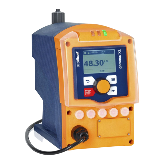
Operating instructions
Solenoid Metering Pump
gamma/ XL, GXLa
EN
Target group: at least "instructed personnel" unless otherwise required.
Please carefully read these operating instructions before use. · Do not discard.
The operator shall be liable for any damage caused by installation or operating errors.
The latest version of the operating instructions are available on our homepage.
Part no. 982271
Original operating instructions (2006/42/EC)
Version: BA G 068 04/22 EN
Advertisement
Table of Contents

Related Manuals for ProMinent gamma XL


Summary of Contents for ProMinent gamma XL
- Page 1 Operating instructions Solenoid Metering Pump gamma/ XL, GXLa Target group: at least "instructed personnel" unless otherwise required. Please carefully read these operating instructions before use. · Do not discard. The operator shall be liable for any damage caused by installation or operating errors. The latest version of the operating instructions are available on our homepage.
- Page 2 Supplemental directives Supplementary information Read the following supplementary information in its entirety! You will benefit more from the operating instructions should you already know this information. The following are highlighted separately in the document: Enumerated lists Fig. 1: Please read! Instructions ð...
-
Page 3: Table Of Contents
Table of contents Table of contents Identity code................6 About This Pump..............9 Safety chapter..............10 3.1 Labels................. 10 3.2 Intended use............... 11 3.3 Safety information............11 3.4 Information in the event of an emergency....14 3.5 Personnel qualification..........14 Storage, Transport and Unpacking........ - Page 4 Table of contents 11.2 ‘Settings’ ..............49 ‘Operating mode’ ..........50 11.2.1 ‘Automatic’ ............55 11.2.2 ‘Stroke length’ ............55 11.2.3 11.2.4 Metering..............56 11.2.5 Concentration............60 11.2.6 Calibrate..............67 11.2.7 System..............68 11.2.8 Inputs/outputs............70 11.2.9 Config-I/Os............. 76 11.2.10 Bleeding............... 76 11.2.11 ‘Priming time’...
- Page 5 Table of contents 15.3.4 Log book entry - Detailed view......112 Decommissioning and disposal........113 Technical data..............115 17.1 Performance data........... 115 17.1.1 Performance data with vPTFE diaphragm... 116 17.2 Accuracy..............116 17.2.1 Standard Liquid End..........116 17.2.2 Self-Bleeding Liquid End........116 17.3 Viscosity..............
-
Page 6: Identity Code
0 without diaphragm rupture indicator 1 with diaphragm rupture indicator, optical sensor, electrical signal Design 0 Housing RAL5003 / Hood RAL2003 Logo 0 with ProMinent logo 2 without ProMinent logo Electrical connection U 100-230 V ± 10%, 50/60 Hz Cable and plug... - Page 7 Identity code Product range gamma/ XL A 2 m European B 2 m Swiss C 2 m Australian D 2 m USA / 115 V 1 2 m open end ..Relay, pre-set to ... 0 no relay 1 1 x changeover contact Fault indicating relay 230 V AC –...
- Page 8 Identity code Product range gamma/ XL Spanish French...
-
Page 9: About This Pump
About This Pump About This Pump About This Pump Pumps in the gamma/ XL product range are microprocessor-con‐ trolled solenoid metering pumps with the following characteristics: Simple adjustment of the capacity directly in l/h Integrated pressure measurement and display for greater safety during commissioning and in the process Bluetooth and Wi-Fi connection for the simple configuration and call-up of process data (optional) -
Page 10: Safety Chapter
Do not open the unit! We would advise that the unit may only be opened by qualified personnel author‐ ised by ProMinent to avoid damage to the unit and guarantee the seamless and safe operation of the unit. All warranty claims will be invalidated if the unit is opened by unauthorised persons. -
Page 11: Intended Use
Observe the general limitations with regard to viscosity limits, chemical resistance and density - see also the ProMinent Resistance List in the Product Catalogue or at www.promi‐ nent.com. - Page 12 Safety chapter WARNING! Danger of electric shock Supply voltage may be present inside the pump housing. – Safely and quickly disconnect the pump from the mains/power supply if the pump housing has been damaged. Only return the pump to operation after an authorised repair.
- Page 13 – Take into account the resistance of the wetted materials and the ProMinent Resistance List when selecting the feed chemical - see the ProMinent Product Catalogue or visit ProMi‐ nent.
-
Page 14: Information In The Event Of An Emergency
Safety chapter Only the ProMinent service department is authorised to open the housing and hood (housing the control elements). Sound pressure level Sound pressure level LpA < 70 dB according to EN ISO 20361 at maximum stroke length, maximum stroke rate, maximum back pressure (water) 3.4 Information in the event of an emergency... - Page 15 Service The Service department refers to service technicians, who have received proven training and have been authorised by ProMinent to work on the system.
-
Page 16: Storage, Transport And Unpacking
Storage, Transport and Unpacking Storage, Transport and Unpacking Safety Information WARNING! Only return metering pumps for repair in a cleaned state and with a flushed liquid end - refer to "Decommissioning! Only return metering pumps with a completed Decontamination Declaration form. The Decon‐ tamination Declaration constitutes an integral part of an inspection / repair order. -
Page 17: Overview Of Equipment And Control Elements
Overview of equipment and control elements Overview of equipment and control elements 5.1 Overview of equipment P_G_0103_SW Fig. 2: Overview of equipment, complete Control unit Drive unit Liquid end P_G_0104_SW Fig. 3: Liquid end with PV bleed valve Discharge valve Backplate Dosing head Bleed valve... -
Page 18: Control Elements
Overview of equipment and control elements 5.2 Control elements Control elements, overview 10 11 P_G_0105_SW Fig. 4 LCD screen [Menu] key Clickwheel [Priming] key [STOP/START] key [Back] key Fault indicator (red) Warning indicator (yellow) Operating indicator (green) 10 "Config I/O” terminal 11 "Diaphragm rupture indicator"... - Page 19 Overview of equipment and control elements Pressure display, identifier and fault displays on the LCD screen CONTACT memory open 12.0 12.0 12000 B0778 Fig. 5: Construction of continuous display Status bar Continuous display, central area Secondary display Refer to the chapter entitled "Main displays and secondary dis‐ plays"...
- Page 20 Overview of equipment and control elements Tab. 2: Identifier and error displays: Identifier Meaning The pump is working or waiting for a starting signal. [STOP/START] key. The pump was manually stopped using the The pump was remotely stopped (Pause) - via the "External" socket. The pump was stopped by an error.
-
Page 21: Key Functions
Overview of equipment and control elements Identifier Meaning ‘Metering è Discharge stroke è HV1’ metering profile has been set. ‘Metering è Suction stroke è HV2’ metering profile has been set. ‘Metering è Suction stroke è HV3’ metering profile has been set. A "Flow Control"... - Page 22 Overview of equipment and control elements Application In the continuous displays In the menu ‘Batch’ oper‐ press Start batch (only in Move to next menu option (or a [Clickwheel] ating mode), continuous display) Acknowledge errors Confirm entry and save turn Switch between the continuous Change figure or change [Clickwheel]...
-
Page 23: Functional Description
Functional description Functional description 6.1 Liquid End The dosing process is performed as follows: The diaphragm is pressed into the dosing head; the pressure in the dosing head closes the suction valve and the feed chemical flows through the discharge valve out of the dosing head. The diaphragm is now drawn out of the dosing head;... - Page 24 Functional description P_G_0074_SW Fig. 7: Discharge stroke metering profiles with stroke L and time t (suction stroke shown as a dotted line) It is possible to selectively also slow the suction stroke with all these metering profiles for the discharge stroke - see . In this way, it is possible to prevent the main cause of inaccurate metering with high viscosity feed chemicals, namely the incomplete filling of the liquid end.
-
Page 25: Dosing Rate
Functional description 6.3 Dosing rate The pump itself regulates the dosing rate that has been set in ‘Automatic’ ON mode. ‘Automatic’ -OFF), the stroke By contrast, in conventional mode ( length and stroke rate determine the dosing rate. The stroke length can be adjusted between 0 and 100% via the continuous display or the menu. -
Page 26: Functions
Functional description 6.6 Functions Refer to the "Hierarchy of Operating Modes, Functions and Fault Statuses" for the order of the various operating modes, functions and fault statuses. ‘Settings’ menu: The following functions can be selected using the "Calibrate" function The pump can also be operated in a calibrated state in all oper‐ ating modes if it is to meter extremely precisely. -
Page 27: Led Displays
Functional description "Fault indicating relay" option The relay can close a connected power circuit (e.g. for an alarm ‘Level horn) in the event of warnings or fault messages (e.g. warning’ ). The function of the relay can be programmed via the menu. The relay can be retrofitted through the slot in the front of the pump –... - Page 28 Functional description The following list shows the order: 1. - Priming 2. - Stop 3. - Error, Pause 4. - Auxiliary dosing rate / Auxiliary frequency 5. - Manual, Analog, Contact, Batch, Fieldbus Comments: re 1. - "Priming" can take place in any pump mode (providing it is working).
-
Page 29: Assembly
Assembly Assembly Refer to the correct dimensional drawings for the pump from the online version of the operating instructions from our website. www.prominent.com Compare the dimensions on the dimensional drawing with those of the pump. CAUTION! Danger from incorrectly operated or inadequately... -
Page 30: Installation, Hydraulic
– Take into account the resistance of the wetted materials and the ProMinent Resistance List when selecting the feed chemical - see the ProMinent Product Catalogue or visit ProMi‐ nent. -
Page 31: Installing Hose Lines
Installation, hydraulic 8.1 Installing hose lines 8.1.1 Installation with metering pumps without degassing Safety information CAUTION! Warning of feed chemical spraying around The lines can become loose or rupture if they are not installed correctly. – Route all hose lines so they are free from mechanical stresses and kinks. - Page 32 Installation, hydraulic CAUTION! Uncontrolled flow of feed chemical The feed chemical can leak through the metering pump in an uncontrolled manner in the event of excessive priming pressure. – Do not exceed the maximum permissible pri‐ ming pressure for the metering pump. INFORMATION: Align the lines so that the metering pump and the liquid end can simply be removed from the side if necessary.
-
Page 33: Installation With Metering Pumps With Degassing
Installation, hydraulic Pipe Union nut Rear clamp ring Front clamp ring Valve P_MAZ_0022_SW Fig. 10: SST designs Installing hose lines - SST design CAUTION! Warning of feed chemical spraying around Connections can come loose in the event that hose lines are installed incorrectly on stainless steel valves. - Page 34 Installation, hydraulic CAUTION! Hazardous feed chemicals can escape With hazardous feed chemicals: Hazardous feed chemical can leak out when using conventional bleeding procedures with metering pumps. – Install a bleed line with a return into the storage tank. Shorten the return line so that it does not dip into the feed chemical in the storage tank.
-
Page 35: Installation, Electrical
Installation, electrical Installation, electrical WARNING! Danger of electric shock A mains voltage may exist inside the device. – Before any work, disconnect the device's mains cable from the mains. WARNING! Risk of electric shock In the event of an electrical accident, the pump must be quickly disconnected from the mains. -
Page 36: Supply Voltage Connector - Power Supply
Installation, electrical CAUTION! Material damage possible due to power surges Should the pump be connected to the mains power supply in parallel to inductive consumers (such as solenoid valves, motors), inductive power surges can damage the control when it is switched off. –... -
Page 37: Hmi Operating Unit
Installation, electrical 9.2 HMI operating unit Connect the HMI to the CAN socket above the LEDs of the pump base if the pump is operated with HMI. If the pump is operated without HMI, then plug the sealing cap sup‐ plied into the CAN socket above the LEDs of the pump base. -
Page 38: External Control" Terminal
Installation, electrical B1080 Fig. 13: Plug to "Config I/O" terminal, pin assignment Configured as an input Parameter Value Voltage with open contacts Input resistance 10 kΩ Max. pulse frequency 50 pulses/s Min. pulse duration 10 ms Tab. 4: Control via: Switching element Specification Potential-free contact... - Page 39 Installation, electrical Electrical interface for pin 1 "Pause" - pin 2 "External contact" - pin 5 "Auxiliary capacity / Auxiliary frequency" Data Value Unit Voltage with open contacts Input resistance 10 kΩ Max. pulse frequency 25 pulse/s Min. pulse duration 20 ms P_BE_0014_SW Fig.
-
Page 40: Level Switch" Terminal
Installation, electrical "External contact" operating mode The pump performs one or more strokes if: Pin 2 and pin 4 are connected to each other for at least 20 ms. At the same time, pin 1 and pin 4 must also be connected to each other. -
Page 41: Metering Monitor" Terminal
Installation, electrical 9.3.3.2 Suction lance with continuous level measurement Electrical interface Designation Function 5 V supply 5 V (4.85 V…5.25 V DC) feed to the sensor and TX communication TX to sensor interface (from the point of view of the pump). Reference potential P_BE_0016_SW RX from sensor... -
Page 42: Relays
Installation, electrical Electrical interface Specification Value Supply voltage, approx.: +5 V, can be loaded to 20 mA (cur‐ rent limitation 150 mA) Power consumption: min. 10 mA, max. 20 mA (sensor presence detection) Sensor signal: potential-free contact (load: 0.5 mA P_DE_0011_SW at +5 V) or Fig. - Page 43 Installation, electrical Menu setting Effect Timer The relay switches when requested by the timer. Fault The relay switches in the event of an error message (red LED*). Warning The relay switches in the event of a warning message (yellow LED*). Warning + error (fault indicating The relay switches in the event of a warning message (yellow LED*) or relay)
- Page 44 Installation, electrical P_SI_0043 Fig. 24: Assignment on the cable Identity code 1 To pin VDE cable Contact CSA cable white N/O (normally open) white Green N/C (normally closed) brown C (common) black P_G_0072_SW Fig. 25: Assignment on the pump 9.3.6.3 Output for other relays (identity code 4) A fault indicating and a pacing relay can be ordered as options - refer to ordering information in the appendix.
- Page 45 Installation, electrical The behaviour is factory-programmed. If another switching function ‘Relay’ menu. is wished, the pump can be reprogrammed in the The variable to be signalled for the current output can be selected ‘ANALOGUE OUTPUT’ menu. in the The current output plus relay can be retrofitted and operates once it is plugged into the board.
-
Page 46: Basic Set-Up Principles
Basic set-up principles Basic set-up principles Please also refer to all the overviews covering – "Operating/set-up overview" and "Operating menu for gamma/ XL, complete" in the appendix and the "Overview of equipment and control elements" and "Control elements” chap‐ ters. The pump exits the menu and returns to a con‐... - Page 47 Basic set-up principles [] Menu. To complete the setting: press ‘Menu’ via the Alternatively: wait 60 seconds or exit the [Menu] key or using ‘End’ . Confirming an entry [Clickwheel] . Briefly press the ð The software switches to the next menu point or back to the menu and saves the entry.
-
Page 48: Checking Adjustable Variables
Basic set-up principles To run through the figures again, if necessary (possibly because of an incorrect figure), when you get to the last [Priming] again - see above Figure, point c). figure press ð Now you can start from the beginning again. Confirming adjustable variables [Clickwheel] 1x. -
Page 49: Set Up / 'Menu
‘Menu’ Set up / ‘Menu’ Set up / Refer to the overviews covering "Operating/set – up overview" and "Operating menu gamma/ XL, complete" in the appendix and in the "Overview of equipment" - "Control elements" chapters by way of supplementary information. The pump exits the menu and returns to a con‐... -
Page 50: Operating Mode
‘Menu’ Set up / ‘Operating mode’ 11.2.1 ‘Menu / Information è Settings è Operating mode è ...’ ‘Manual’ 11.2.1.1 ‘Menu / Information è Settings è Operating mode Manual’ è ‘Manual’ operating mode lets you operate the pump manually. The capacity and/or stroke rate and stroke length can be set in the continuous displays in this operating mode. - Page 51 ‘Menu’ Set up / ‘Automatic’ ‘Off’ ) factor The number of strokes per pulse depends on the factor which you can input. By using a factor you can multiply incoming pulses by a factor between 1.01 to 99.99 or reduce them by a factor of 0.01 to 0.99: Number of strokes executed = factor x number of incoming pulses...
- Page 52 ‘Menu’ Set up / If a remainder is obtained when dividing by the factor, then the unit adds the remainders together. As soon as this sum reaches or exceeds "1", the pump executes an additional stroke. Therefore on average during the metering operation, the resul‐ tant number of strokes precisely matches the factor.
- Page 53 ‘Menu’ Set up / CAUTION! – The pump maintains its stroke rate when ‘Manual’ operating mode changing over from ‘Batch’ operating mode. [STOP/START] or the – When you press ‘Memory’ is "Pause" function is activated, the cleared. In operation, the batch size can be changed more easily by using the "Batch size"...
- Page 54 ‘Menu’ Set up / I [mA] B0088 Fig. 33: Frequency-current diagram for "Linear curve" Plot a diagram similar to the one above – with values for (I1, F1) and (I2, F2) – so that you can set the pump as desired! The smallest processable difference between I1 and I2 is 4 mA (ll I1-I2 ll ≥4 mA).
-
Page 55: Automatic
‘Menu’ Set up / Using this processing type, you can control a metering pump using the current signal as shown in the diagram above. ‘Lower side band’ type of Everything functions according to the processing. ‘Automatic’ 11.2.2 ‘Menu / Information è Settings è Automatic è ...’ ‘Automatic’... -
Page 56: Metering
‘Menu’ Set up / 11.2.4 Metering ‘Menu / Information è Settings è Metering è ...’ ‘Discharge stroke’ 11.2.4.1 ‘Menu / Information è Settings è Metering Discharge stroke è ...’ è In the ‘Settings’ - ‘Discharge stroke’ sub-menu, you can precisely match the pump metering flow over time to the requirements of the particular application. - Page 57 ‘Menu’ Set up / P_G_0125_SW Fig. 35: Discharge stroke metering profiles with stroke L and time t (suction stroke shown as a dotted line) ‘Suction stroke’ 11.2.4.2 ‘Menu / Information è Settings è Metering Suction stroke è ...’ è It is possible to selectively also slow the suction stroke with all these metering profiles for the discharge stroke - see .
- Page 58 ‘Menu’ Set up / P_G_0075_SW normal Fig. 36: Suction stroke metering profiles with stroke L and time t Normal Normal suction stroke Suction stroke for viscous feed chemical Suction stroke for average viscosity feed chemical Suction stroke for high-viscosity feed chemical –...
- Page 59 ‘Menu’ Set up / Pressure rating / Size of liquid 1020 0730 0450 Switch-off pressure Switch-off pressure: Pressure above which the unit is switched off for the medium term in the event of excess pressure = Pressure rating plus 10 ... 20%. ‘Monitoring’...
-
Page 60: Concentration
‘Menu’ Set up / 11.2.4.4.4 Message when no pressure You can have the pump output a message in the event of no pres‐ ‘Message when no pressure’ func‐ sure using the programmable tion. 11.2.4.4.5 Cavitation You can have the pump output a message in the event that it iden‐ ‘Cavitation’... - Page 61 ‘Menu’ Set up / The "Concentration" continuous display only – appears, if: the pump is calibrated. – the ‘Concentration’ menu was run through – in the operating mode used. and ‘Concentration control’ was switched – to ‘active’ - in the operating mode being used.
- Page 62 ‘Menu’ Set up / Procedure CAUTION! The precision of the concentration is strongly dependent on: – the precision of the metering pump calibration. – the precision of the inputs. Calibrate the metering pump if it is not yet calibrated - see ‘Settings’...
- Page 63 ‘Menu’ Set up / CAUTION! Danger of too high concentrations The metering pump can continue to meter if the flow falls or stops entirely. – Take system-based precautions to prevent the metering pump from continuing to meter in these circumstances. The prerequisites are that: the flowing medium has the same density as water (1 kg/l ≜...
- Page 64 ‘Menu’ Set up / Tab. 14: Possible values of adjustable variables Adjustable variable Lower value Upper value Increment Contact gap in l/contact 000.10 999.99 000.01 Mass concentration in % 000.01 100.00 000.01 Mass density in kg/l 0.50 2.00 0.01 ‘Batch’ operating mode (settings for the ‘Concentration’ function) 11.2.5.3 ‘Menu / Information è...
- Page 65 ‘Menu’ Set up / [Menu] Press ð A continuous display appears. [Clickwheel] to go to the "Concentration" contin‐ Press the uous display (ppm or %). You can enter the desired mass concentration using the [Clickwheel] . Tab. 15: Possible values of adjustable variables Adjustable variable Lower value Upper value...
- Page 66 ‘Menu’ Set up / Calibrate the metering pump if it is not yet calibrated - see ‘Settings’ - ‘Calibration’ chapter. chapter ‘Automatic’ - ‘on’ Check whether the metering pump is set to metering mode. ‘Analogue’ operating mode and confirm with the Select [Clickwheel] .
-
Page 67: Calibrate
‘Menu’ Set up / Tab. 16: Possible values of adjustable variables Adjustable variable Lower value Upper value Increment 0000.1 9999.9 0000.1 Max. flow in m Mass concentration in % 000.01 100.00 000.01 Mass density in kg/l 0.50 2.00 0.01 11.2.6 Calibrate ‘Menu / Information è... -
Page 68: System
‘Menu’ Set up / P_G_0071_SW [Clickwheel] to scroll through the continuous displays Preparation Use the to check whether litres or gallons have been selected. If the incorrect volume unit has been selected, correct it in ‘Menu / Information è Settings è System Volume unit’... - Page 69 ‘Menu’ Set up / ‘System’ menu splits into the following sub-menus: ‘Dosing head’ ‘Volume unit’ ‘Pressure unit’ ‘Pressure adjustment’ ‘Start behaviour’ ‘Dosing head ’ 11.2.7.1 ‘Menu / Information è Settings è System è Dosing head ...’ è CAUTION! – Should a different liquid end size be fitted, then the pump must be reprogrammed in the ‘Dosing head’...
-
Page 70: Inputs/Outputs
‘Menu’ Set up / There is no ‘Pressure adjustment’ sub-menu with pumps with SER dosing heads. Requirements: A manometer is installed in the discharge line. Everything is set on the pump. ‘Pressure adjustment’ sub-menu. Shift to the ð The ‘Start pump’ menu item appears. [Clickwheel] to confirm ‘Yes’... - Page 71 ‘Menu’ Set up / ‘Inputs/outputs’ menu is split into the following sub-menus: ‘Auxiliary capacity’ / ‘Auxiliary frequency’ ‘Relay1’ (optional) ‘Relay2’ (optional) ‘Flow monitor’ (only if connected) ‘Diaphragm rupture’ (only if connected) ‘Pause input’ (optional) ‘Niveau monitoring’ ‘Auxiliary capacity’ / ‘Auxiliary frequency’ 11.2.8.1 ‘Menu / Information è...
- Page 72 ‘Menu’ Set up / Menu setting Effect Timer The relay switches when requested by the timer. Error The relay switches in the event of a fault message (red LED*). Warning The relay switches in the event of a warning message (yellow LED*). Warning + error The relay switches in the event of a warning message (yellow LED*) or a fault message (red LED*).
- Page 73 ‘Menu’ Set up / 11.2.8.4 mA output ‘Menu / Information è Settings è Inputs/outputs mA-Output è ...’ è You can enter here which signal is to be output similar to the pump capacity and as an mA signal and how the pump is to respond. The following can be selected one after the other - Table display: ‘mA-Output’...
- Page 74 ‘Menu’ Set up / The setting options for the ‘Flow control’ function are only available if a flow control is electrically installed. The symbol for flow control appears: A metering monitor, such as a Flow Control (also DulcoFlow ), can ®...
- Page 75 11.2.8.8.2 Continuous Calibrate The ProMinent suction lance with continuous level measurement can measure the liquid level in a 30-litre canister with 5 % preci‐ sion. The relevant secondary display of the gamma/ XL indicates the liquid level, or the liquid level can be reported to the control panel by bus.
-
Page 76: Config-I/Os
(retrofittable), the pump can be bled via a bleed relay. There are 2 hardware options for automatically bleeding the dis‐ charge side: via ProMinent's bleed module in the liquid end. via a customer implemented bleed facility in the discharge line. The relay - "Relay” – "with automatic bleed" - changes its switching status for the period during which the pump is priming. -
Page 77: Priming Time
‘Menu’ Set up / Detailed explanation: ‘Off’ has been selected in the menu, this function is deacti‐ 1 - If vated. ‘Periodic’ was selected in the menu, then the control unit 2 - If periodically triggers the bleed procedure with an adjustable ‘cycle’... -
Page 78: Set Time
‘Menu’ Set up / In the ‘Priming time’ menu, you can select how long the metering [Priming] has been pressed. pump is to prime once In operation, the stroke length can be changed more easily using the "Priming time" display: Press [Priming] - the pump starts to prime. -
Page 79: Activation / Deactivation
‘Menu’ Set up / stop / start the pump ‘Batch (time)’ ) trigger a batch ( 11.3.1 Activation / deactivation ‘Menu / Information è Timer è Activation è ...’ You can only program the timer when ‘Activation’ is set to ‘inactive’ . ‘Activation’... - Page 80 ‘Menu’ Set up / The following administration functions are available to manage the commands (program lines): ‘New’ ) 1 - Reprogram program line ( ‘Show’ ) 2 - Check program line ( ‘Change’ ) 3 - Change program line ( ‘Clear’...
- Page 81 ‘Menu’ Set up / Time event (trigger) Action Workdays 1 Time of day Manual 20.00 l/h (Mo-Fr) 12:00 This corresponds to the following instruction: WHEN triggering event, THEN action The time event (trigger) defines what action or at what time an action is to take place.
- Page 82 ‘Menu’ Set up / Tab. 19: Action Action Description Value ‘Manual’ ‘Dos. capacity’ ) Switch over in this operating mode Litre/h ( ‘Manual’ ‘Dos. capacity’ ) Switch over in this operating mode Litre/h *1 ( ‘Metering rate’ ) + Strokes/h *2 ( ‘Stroke length’...
- Page 83 ‘Menu’ Set up / ‘Init’ Initial conditions 11.3.2.1.2 ‘Init’ can be used to set initial conditions at The triggering event the beginning of a program sequence. Example triggering event (trigger) Action Init Relay 2 closed Init Contact The example means: ‘Timer è...
- Page 84 ‘Menu’ Set up / A time event lets you trigger an action precisely to the minute. If the action is to be triggered precisely to the second, then you need to set up your programming on a delayer. 11.3.2.1.4 Delayer A delayer lets you delay an action with regard to a time event (trigger).
- Page 85 ‘Menu’ Set up / 11.3.2.1.5 Inputs ‘Config I/O’ socket A 0/1 contact signal, for example at pin 1 of the can be a triggering event. Example Time events (triggers) Action Config I/O 1 Relay 2 open The example means: ‘Config I/O’ If a 0/1 contact signal is closed between pin 1 of the ‘Relay 2’...
- Page 86 ‘Menu’ Set up / For details on the sorting sequence of the pro‐ – gram lines see Ä ‘Sorting sequence’ on page 86. The timer program can have a maximum of 99 – program lines. ‘Show’ ) 11.3.2.3 Check program lines ( ‘Menu / Information è...
-
Page 87: Clear All
‘Menu’ Set up / ‘Change’ ) 11.3.2.4 Change program lines ( ‘Menu / Information è Timer è Set timer è Change’ [Clickwheel] to select the required program line / Use the instruction according to its number and press the [Clickwheel] . Click through the instruction and change it. - Page 88 ‘Menu’ Set up / Task: Example of "Weekday metering" The pump is to meter 2 litres every half hour every weekday (Mon-Fri) between 8:00 and 11:00. Solution: As you define switching times with the timer, you need to first define the switching points at 08:30, 09:30 and 10:30. To meter 2 litres, the pump needs to work in ‘Manual’...
- Page 89 ‘Menu’ Set up / Test your programming! The secondary display “Timer” can help with this as it shows the next instruction and the remaining time. (To [Clickwheel] in a access this secondary display, press the continuous display until a long series of small circles [Clickwheel] to navi‐...
- Page 90 ‘Menu’ Set up / Example - to avoid errors The example is intended to provide the programmer with a couple of “programming obstacles” that he might not immediately see: Com‐ Time event Additional Action Additional Comment mand parameter parameter Config I/O 1 Input, reacts Start Delayer 1 When a contact...
-
Page 91: Timer Information
‘Menu’ Set up / ‘Delayer 1’ - ‘60 s’ and If, for example, you are using ‘Delayer 1’ - ‘120 s’ , then the action is never performed after the second (longer) delay time because the delayer has been activated after the shorter delay time and becomes inactive. -
Page 92: Brief Explanation Of Selected Functions
‘Menu’ Set up / Problem Possible cause of fault Remedy ‘Init’ instruction with The pump starts pumping unex‐ The timer clears every “Manual” Enter an ‘Halt’ action. pectedly. stop when activated - see “Timer behaviour on start” The timer does not react to a Config I/O was not configured as Configure Config I/O as “Config contact signal at the corre‐... -
Page 93: Service
‘Menu’ Set up / Inputs Pins 1 - 3 of the "Config I/O” socket can be inputs and outputs. That can be programmed. Delayer Delayers are started event- or time-controlled. On expiry of the delay time, the delayer itself can trigger any actions. ‘Service’... -
Page 94: Password
‘Menu’ Set up / ‘Password ’ 11.4.2 ‘Menu / Information è Service è Password è ...’ ‘Change You can enter a password of your choice in the password’ menu. ‘Clear counters’ 11.4.3 ‘Menu / Information è Service è Clear counters è ...’ You can reset the counters to "0"... -
Page 95: Diaphragm Replacement
‘Menu’ Set up / Line Information Switching-on duration, stroke rate since switching Room temperature, status information on the error (for developers) ‘Diaphragm replacement’ 11.4.5 ‘Menu / Information è Service è Diaphragm replacement ...’ è You can move the slide rod into the "replacement position" here ‘To change position’... -
Page 96: Language
‘Menu’ Set up / ‘Language’ 11.5 ‘Menu / Information è Language è ...’ ‘Language’ You can select the desired operating language in the menu. -
Page 97: Operation
Operation Operation This chapter describes all the operating options in a continuous display (several symbols and the pressure display appear at the top in the black bar) for the person trained on the pump. Please also refer to the "Operating/Setting –... - Page 98 Operation Contact volume Batch dosing time Concentration Set-up overview gamma/ XL Continuous display Stop/start pump STOP STOP START START Priming Start batch (only in "Batch" operating mode) Acknowledging errors Check adjustable values Changing directly changeable variables Setting mode B0598 Fig. 38: Control options using keys and locking options [Clickwheel] Press [Clickwheel]...
-
Page 99: Maintenance
Maintenance Maintenance WARNING! It is mandatory that you read the safety information and specifications in the "Storage, Transport and Unpacking" chapter prior to shipping the pump. CAUTION! Warning of feed chemical spraying around Feed chemical may spray out of the hydraulic com‐ ponents if they are tampered with or opened due to pressure in the liquid end and adjacent parts of the system. - Page 100 Maintenance P_G_0054_SW Fig. 39: The leakage hole Interval Maintenance work Personnel Annually* Check the diaphragm for damage - refer to "Repair" Technical personnel * Under normal loading (approx. 30% of continuous operation). Under heavy-duty loading (e.g. continuous operation): Shorter intervals. Check the metering diaphragm more frequently or use a dia‐...
-
Page 101: Repair
Repair Repair Safety information User qualification, mechanical repair: trained and qualified per‐ sonnel. User qualification, electrical repair: electrical technician. WARNING! Danger from hazardous substances! Possible consequence: Fatal or very serious inju‐ ries. Please ensure when handling hazardous sub‐ stances that you have read the latest safety data sheets provided by the manufacture of the haz‐... -
Page 102: Replacing The Diaphragm
Repair 14.1 Replacing the diaphragm The order no. (part number) of the appropriate diaphragm or the ‘Service’ menu. spare parts kit can be found at the end of the Take protective measures, if necessary. Note the material safety data sheet for the feed chemical. Prevent the escape of feed chemical. -
Page 103: Replacing The Vptfe Diaphragm
Repair Tentatively screw the new diaphragm (3) onto the drive axle as far as the stop - ensure that this is successful, otherwise the pump will not subsequently meter precisely. Unscrew the diaphragm (3) again. Place the backplate (4) onto the pump housing (6). Make sure that the leakage hole points downwards when the pump is in its subsequent fitting position - see figure in the "Maintenance"... -
Page 104: Cleaning The Diaphragm Rupture Indicator
Repair Pump type 2.0 diaphragm complete 2.0 spare parts kit PVM 2.0 spare parts kit PVN 1612 1117433 1119828 1119829 1020 1117354 1121492 1121491 0730 1117352 1118459 1118464 0450 1117353 1120526 14.2 Cleaning the diaphragm rupture indicator After the diaphragm rupture indicator has been triggered, any res‐ idue of feed chemical may affect its function. -
Page 105: Troubleshooting
Troubleshooting Troubleshooting Safety information WARNING! Warning of hazardous feed chemical Should a dangerous feed chemical be used: it may escape from the hydraulic components when working on the pump, material failure or incorrect handling of the pump. – Take appropriate protective measures before working on the pump (e.g. -
Page 106: Faults With Error Message
Troubleshooting 15.2 Faults with error message 15.2.1 Fault messages on the LCD screen In the event of a fault: the red LED display lights up. an identifier and a message appear on the LCD screen. the pump stops. Fault description Cause Remedy Personnel... - Page 107 Troubleshooting Fault description Cause Remedy Personnel The pump has detected too Rectify the cause and Technical No. 11: The identifier and the ‘Overload’ appear. high a back pressure. acknowledge the error. personnel message The current is too high. Rectify the cause and Technical No.
-
Page 108: Warning Messages On The Lcd Screen
The fan is faulty or not con‐ Return the pump to No. 5: The identifier and the ‘Fan warning’ appear. nected. ProMinent. message An internal system warning Return the pump to No. 6: The identifier appears fol‐ ‘System or an incorrect solenoid ProMinent. -
Page 109: All Other Faults
‘Cavitation’ . 15.2.3 All other faults Please contact the responsible ProMinent branch or representa‐ tive! 15.3 Log book 15.3.1 Fault messages in the log book For more information on the ‘ERROR’ messages - refer to the chapter "Fault messages on the LCD... -
Page 110: Warning Messages In The Log Book
The associated heartbeat message was no longer received by the power unit for a certain period of time (power unit no longer reached?) Error versions * * Please get in touch with the ProMinent head office should this fault occur. 15.3.2 Warning messages in the log book For more information on the ‘WARNING’... -
Page 111: Event Messages In The Log Book
Troubleshooting 15.3.3 Event messages in the log book Tab. 26: Events Log book no. Description Head change is active – dongle was inserted. Parameter menu called up – dongle was inserted. Air gap measured – dongle was inserted. Too high current was detected but no fault message generated. Automatic bleed was active. -
Page 112: Log Book Entry - Detailed View
Troubleshooting 15.3.4 Log book entry - Detailed view [Clickwheel] to obtain more information about a log book Press the entry. Tab. 27: Information on the detailed view Line Information Date/time Type of entry (fault, warning ...) Total operating time, total number of strokes Switching-on duration, stroke rate since switching Room temperature, status information on the error (for developers) -
Page 113: Decommissioning And Disposal
Decommissioning and disposal Decommissioning and disposal Decommissioning WARNING! Danger from chemical residue There is normally chemical residue in the liquid end and on the housing after operation. This chemical residue could be hazardous to people. – It is mandatory that the safety information in the "Storage, transport and unpacking"... - Page 114 Decommissioning and disposal Disposal WARNING! Eye injury from compression spring A compression spring is fitted in the pump in the drive magnet, which could cause eye injuries when opened. – Do not dismantle the pump to dispose of it. CAUTION! Risk to the environment from the battery There is a battery in the pump, which can have a toxic effect on the environment.
-
Page 115: Technical Data
Technical data Technical data 17.1 Performance data Tab. 28: At 200 strokes/minute and 100% stroke length Liquid Minimum pump capacity Max. Connector Suction Priming Max. pri‐ Weight stroke size lift* lift ming pres‐ type rate sure on outer Æ x the suc‐... -
Page 116: Performance Data With Vptfe Diaphragm
Technical data 17.1.1 Performance data with vPTFE diaphragm Tab. 29: at 200 strokes/minute and 100% stroke length Type Pump capacity Connector Suction lift* Priming Max. pri‐ size lift** ming pres‐ at maximum back pressure sure on the outer Æ x suction inner Æ... -
Page 117: Viscosity
Technical data 17.3 Viscosity Tab. 30: The liquid ends are suitable for the following viscosity ranges: Design Viscosity in mPas Standard 0 ... 200 With valve springs 201 ... 500 With HV head 501 ... 3000* Self-degassing (SEK) 0 ... 50 * Even significantly higher with correctly adjusted installation. -
Page 118: Electrical Data
Technical data 17.5 Electrical data Design: 100 - 230 V ±10%, 50/60 Hz Specification Value Nominal power, approx. 78 W Switch on peak current, (within approx. 50 ms 8 ... 4 A falling prevention T 3.15 A * * 250 V (1.5kA), Order no. 732414 Fuses must have VDE, UL and CSA certification. -
Page 119: Altitude Of Site
Technical data 17.8 Altitude of site Data Value Unit Altitude of site , max.: 2000 m above 17.9 Degree of protection and safety requirements Degree of protection Protection against contact and moisture: IP 66 according to DIN EN 60529 Safety requirements Protection class 1 - mains connection with protective conductor 17.10 Compatibility Some hydraulic parts of the delta... -
Page 120: Exploded Drawings Of The Gamma/ Xl
Exploded drawings of the gamma/ XL Exploded drawings of the gamma/ XL You can replace the standard diaphragms 1:1 with vPTFE dia‐ phragms. You simply require a new vPTFE diaphragm. Liquid end 1608 / 2508 NP_2 P_G_0108_SW 40350932 Fig. 41: Liquid end of gamma/ XL 1608 / 2508 NP_2 Tab. - Page 121 Exploded drawings of the gamma/ XL Liquid end gamma/ XL NPE2 1608 2508 Liquid end with degassing 1096278 1096279 Spare parts kit 1030620 1033172 Diaphragm 1030353 1030353 Liquid end gamma/ XL NPB2 1608 2508 Liquid end with degassing 1096282 1096283 Spare parts kit 1030611 1033171...
- Page 122 Exploded drawings of the gamma/ XL Liquid end gamma/ XL NPT2 1612 1020 0730 Liquid end with degassing 1096275 1096273 1096274 Spare parts kit 1027081 1027082 1095626 Diaphragm 1000248 1000249 1045456 Liquid end gamma/ XL NPE2 1612 1020 0730 Liquid end with degassing 1096270 1096261 1096260...
- Page 123 Exploded drawings of the gamma/ XL Tab. 34: Spare parts for liquid end gamma/ XL 1608 NPT7, self-degassing SER Pos. Designation Connector kit Discharge valve Diaphragm Suction valve Liquid end gamma/ XL NPT 7 1608 Liquid end with degassing 1096271 Spare parts kit 1047831 Diaphragm...
- Page 124 Exploded drawings of the gamma/ XL Liquid end gamma/ XL NPT 7 1612 1020 0730 Liquid end with degassing 1096272 1096266 1096267 Spare parts kit 1047832 1047833 1095503 Diaphragm 1000248 1000249 1045456 Liquid end 1608 / 2508 NP_0 P_G_0107_SW 40350920 Fig.
- Page 125 Exploded drawings of the gamma/ XL Liquid end gamma/ XL NPB 0 1608 2508 Liquid end without degassing 1096280 1096281 Spare parts kit 1030611 1033171 Diaphragm 1030353 1030353 Liquid end 1612 - 0730 NP_0 P_G_0107_SW 40350920 Fig. 46: Liquid end of gamma/ XL 1612 - 0730 NP_0 Tab.
- Page 126 Exploded drawings of the gamma/ XL Liquid end gamma/ XL NPB 0 1612 1020 0730 Liquid end without degassing 1096284 1096285 1096262 Spare parts kit 1030525 1030526 1030612 Diaphragm 1000248 1000249 1045456 Liquid end 1608 PV_2 P_G_0109_SW 40351206 Fig. 47: Liquid end of gamma/ XL 1608 PV_2 Tab.
- Page 127 Exploded drawings of the gamma/ XL Liquid end gamma/ XL PVT 7, SER 1608 Liquid end, self-degassing SER 1096251 Spare parts kit 1047831 Diaphragm 1030353 Liquid end gamma/ XL PVF2, FDA 1608 Liquid end with degassing 1096252 Spare parts kit 1083565 Diaphragm 1030353...
- Page 128 Exploded drawings of the gamma/ XL Liquid end gamma/ XL PVT 2 1612 1020 0730 Liquid end with degassing 1096264 1096258 1096257 Spare parts kit 1027081 1027082 1095626 Diaphragm 1000248 1000249 1045456 Liquid end gamma/ XL PVT 7, SER 1612 1020 0730 Liquid end, self-degassing SER...
- Page 129 Exploded drawings of the gamma/ XL Liquid end 0450 / 0280 PV_2 P_G_0127_SW 40344218 Fig. 49: Liquid end of gamma/ XL 0450 / 0280 PV_2 Tab. 40: Spare parts for liquid end gamma/ XL 0450 / 0280 PV_2 Pos. Designation Connector kit Discharge valve Diaphragm...
- Page 130 Exploded drawings of the gamma/ XL Liquid end 1608 / 2508 SST0 P_G_0110_SW 40351259 Fig. 50: Liquid end of gamma/ XL 1608 / 2508 SST0 Tab. 41: Spare parts for liquid end gamma/ XL 1608/2508 SST0 Pos. Designation Connector kit Discharge valve Diaphragm Suction valve...
- Page 131 Exploded drawings of the gamma/ XL Liquid end 1612 - 0730 SST0 P_G_0111_SW 40351296 Fig. 51: Liquid end of gamma/ XL 1612 - 0730 SST0 Tab. 42: Spare parts for liquid end gamma/ XL 1612 - 0730 SST0 Pos. Designation Connector kit Discharge valve Diaphragm...
- Page 132 Exploded drawings of the gamma/ XL Liquid end 0450 - 0280 SST0 P_G_0116_SW 40352959 Fig. 52: Liquid end of gamma/ XL 0450 - 0280 SST0 Liquid end gamma/ XL SST0 0450 0280 Liquid end without degassing 1096218 1096235 Spare parts kit 1095625 1095624 Diaphragm...
- Page 133 Exploded drawings of the gamma/ XL Liquid end 1608 / 1612 / 1020 PVT4, P_G_0113_SW 40353013 Fig. 53: Liquid end gamma/ XL 1608 / 1612 / 1020 PVT4, HV Tab. 43: Spare parts for liquid end gamma/ XL 1608 / 1612 / 1020 PVT4, HV Pos.
- Page 134 Exploded drawings of the gamma/ XL Liquid end gamma/ XL 0730 PVT4, P_G_0114_SW 40353046 Fig. 54: Liquid end gamma/ XL 0730 PVT4, HV Tab. 44: Spare parts for liquid end gamma/ XL 0730 PVT4, HV Pos. Designation Connector kit with hose sleeve Diaphragm Liquid end gamma/ XL 0730 PVT4, 0730...
-
Page 135: Dimensional Drawings
Dimensional drawings Dimensional drawings Compare the dimensions on the dimensional – drawing with those of the pump. All dimensions are in mm. – Dimensional drawing gamma/ XL, material versions NP P_G_0098_SW 40353314 Fig. 55 2508 1608 1612 1020 0730 ØA C (with bleed valve) C (without bleed valve) - Page 136 Dimensional drawings Dimensional drawing gamma/ XL, material version PV 26.5 P_G_0099_SW 40353347 Fig. 56 1608 1612 1020 0730 ØA C (with bleed valve) C (SER)
- Page 137 Dimensional drawings Dimensional drawing gamma/ XL, material version PV DN10 P_G_0100_SW 40353421 Fig. 57 0280 0450 ØA...
- Page 138 Dimensional drawings Dimensional drawing gamma/ XL, material version PV HV P_G_0102_SW 40353808 Fig. 58 1608 1612 1020 0730 ØA Dimensional drawing gamma/ XL 1608/ 2508, material version SS P_G_0101_SW 40353449 Fig. 59...
- Page 139 Dimensional drawings Dimensional drawing gamma/ XL, material version SS P_G_0126_SW 40353700x01 Fig. 60 1612 1020 0730 ØA ØF...
- Page 140 Dimensional drawings Dimensional drawing gamma/ XL, material version SS DN10 P_G_0121_SW 40354302 Fig. 61 0450 0280 ØA...
-
Page 141: Declaration Of Conformity For Machinery
In accordance with DIRECTIVE 2006/42/EC OF THE EUROPEAN PARLIAMENT AND OF THE COUNCIL, Appendix I, BASIC HEALTH AND SAFETY REQUIREMENTS, section 1.7.4.2. C. ProMinent GmbH Im Schuhmachergewann 5 - 11 D - 69123 Heidelberg, Germany, hereby declare that the product specified below complies with the... -
Page 142: Declaration Of Conformity
UK Declaration of Conformity UK Declaration of Conformity ProMinent GmbH Im Schuhmachergewann 5 - 11 D - 69123 Heidelberg Germany herby declare that the product identified below conforms to the basic health and safety requirements of the Regulations, by virtue of its design and construction, and in the configuration placed on the market by us. -
Page 143: Operating / Set-Up Overview Gamma/ Xl
Operating / set-up overview gamma/ XL Operating / set-up overview gamma/ XL Continuous display Stop/start pump STOP STOP START START Priming Start batch (only in "Batch" operating mode) Acknowledge errors Check adjustable variables Change directly adjustable variables Information Operating Settings mode Automatic Stroke length*... - Page 144 Operating / set-up overview gamma/ XL Timer Service Language B1156...
-
Page 145: Gamma/ Xl Operating Menu, Overall
gamma/ XL operating menu, overall gamma/ XL operating menu, overall 1. level Information Versions Control Hardware Software Bootloader Power Hardware Software Bootloader HMI data Time Date Max. capacity *1 Max. capacity *2 Serial number Identity code Switch-on counter Total operating time Total number of strokes... - Page 146 gamma/ XL operating menu, overall 1. level Stroke length *2 1 ... 100% Dosing Discharge stroke optimum fast sine mode continuous DFMa Suction stroke normal Pressure stage x bar Monitoring Air lock Inactive Warning Fault Air sensitivity normal average weak Message with Warning overpressure...
- Page 147 gamma/ XL operating menu, overall 1. level ‘Batch’ : Concentration of Volume main feed chemical medium ‘Analogue’ : Concentration of Max. flow of main feed chemical medium Calibration Calibration factor Calibration factor Calibration Start calibration Calibration ended Calibra‐ tion result System Dosing head Self-bleeding:...
- Page 148 gamma/ XL operating menu, overall 1. level Relay 1 Relay1 type Timer Fault Warning Warning + error Warning, error + stop Pump active Cycle quantity Stroke rate Metering / Batch Bleeding Relay 1 polarity energizing (N/O) releasing (N/C) Relay cycle quan‐ 01.000 l tity Relay 2...
- Page 149 gamma/ XL operating menu, overall 1. level continuous Calibration Configure Config I/Os Set Config I/Os Config I/O 1 Config I/O 2 Timer input Config I/O 3 Timer output Selective fault Selective warning Stroke rate Cycle quantity Metering / Batch Fault Warning Warning + error Warning, error +...
- Page 150 gamma/ XL operating menu, overall 1. level Sunday the 1st, 2nd, 3rd, 4th, Location Northern Hemi‐ sphere Southern Hemi‐ sphere Date dd.mm.yyyy Timer Timer status Activation Active Inactive Setting the timer Command 01 Hourly Displays Anweisung2 Daily (Mon-Sun) Change … Weekdays1 (Mo- Clear Weekdays2 (Mo-...
- Page 151 gamma/ XL operating menu, overall 1. level Diaphragm Back replacement To change posi‐ tion Display Brightness Contrast Password? Factory setting Diaphragm part number: ------- Spare parts kit part number: ------- Language English German Frenchç Spanishñ Italian ‘Automatic’ - ‘on’ - see Chap. ‘Set Up’ - ‘Settings’ - *1 with ‘Automatic’...
-
Page 152: Continuous Displays And Secondary Displays
Continuous displays and secondary displays Continuous displays and secondary displays... - Page 153 Continuous displays and secondary displays...
-
Page 154: Installation Instructions: Retrofitting, Relays
Installation instructions: Retrofitting, relays Installation instructions: Retrofitting, relays Tab. 47: These installation instructions apply to: Designation Order no. Fault indicating relay 1050643 Fault indicating and pacing relay 1050654 Fault indicating relay + 4-20 mA output 1050655 Materials Torx spanner T 25. A pocket torch can help to find the 4x2 contact in the slot for the relays more easily. -
Page 155: Index
Index Index 1, 2, 3 ... Bleeding ......42, 76 Selective errors ..... . . 76 . - Page 156 Index Date ......49, 78, 94, 112 Factor ......50, 52 Declaration of Conformity .
- Page 157 Index Installation, hydraulic ..... . 30 Metering monitor ..... . 41, 73 Selective warning .
- Page 158 Index Priming ......27, 97 Set-up overview ......143 Priming time .
- Page 159 Index Sorting sequence ..... . 86 Timer ........78 1 time event - several actions .
- Page 160 ProMinent GmbH Im Schuhmachergewann 5 - 11 69123 Heidelberg Germany Telephone: +49 6221 842-0 Fax: +49 6221 842-419 Email: info@prominent.com Internet: www.prominent.com 982271, 3, en_GB © 2022...
Need help?
Do you have a question about the gamma XL and is the answer not in the manual?
Questions and answers