Table of Contents
Advertisement
Operating Instructions Manual
®
ProMinent
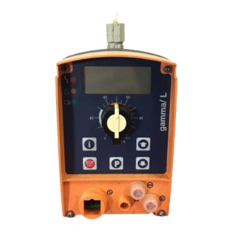
gamma/ L
Solenoid Dosing Pump
Please affix nameplate here!
Please read the operating instructions through completely before commissioning this equipment! Do not discard!
Any part which has been subject to misuse is excluded from the warranty!
Part No. 987604
ProMinent Dosiertechnik GmbH
69123 Heidelberg
Germany
BA G 015 10/00 GB
•
•
Advertisement
Table of Contents

Related Manuals for ProMinent gamma/ L


Summary of Contents for ProMinent gamma/ L
- Page 1 Operating Instructions Manual ® ProMinent gamma/ L Solenoid Dosing Pump Please affix nameplate here! Please read the operating instructions through completely before commissioning this equipment! Do not discard! Any part which has been subject to misuse is excluded from the warranty! Part No.
- Page 2 Printing Printing: Operating Instructions ProMinent ® gamma/ L © ProMinent Dosiertechnik GmbH, 1999 Address: ProMinent Dosiertechnik GmbH Im Schuhmachergewann 5-11 D-69123 Heidelberg Postfach 101760 D-69007 Heidelberg info@prominent.de www.prominent.de Subject to technical alteration. È Please fold out this page! ProMinent ®...
- Page 3 Press x2 For “change individual digits”: jumps to first digit Arrow keys UP and DOWN Press x1 Change directly alterable values Select other settings, (until “Set” appears) change individual digit or figure Press simultaneously Prime ProMinent ®...
- Page 4 Operating-/Settings Diagram Continuous display Start/stop pump STOP STOP START START = Lock (CODE 1) = Lock (CODE 2) Change directly alterable values Prime Start batch (in"batch" operating mode only) Cancel error Check adjustable values Analog Manual Analog Manual Contact Batch Contact Batch Analog...
- Page 5 Contact Contact Contact Contact Contact Contact Contact Contact Contact Contact Batch Batch Batch Batch Batch Batch Batch Batch Batch Batch Batch Batch Batch Batch Calib Calib Calib Calib Calib Calib Calib Calib Calib Calib Calib Calib Calib Calib Calib Freq. Freq.
- Page 6 Continuous display Operating mode "Contact" with Operating mode "Batch" with Continuous Operating mode "Analog" 0-20 mA Operating mode "Manual" display memory and tansfer factor 5 memory and tansfer factor 5 & & & & Stop Stop Stop...
-
Page 7: Table Of Contents
Cancel total stroke number or total litres (CLEAR window) ............8 Commissioning .................................... Precision dosing settings ............................Diagrams for setting feed capacity ........................9 Operating ......................................Manual operation ................................Remote control ................................. 10 Maintenance ....................................11 Repairs ........................................ 12 Troubleshooting ..................................13 Decommissioning and Disposal ..........................ProMinent ®... - Page 8 ............................... 14.7 Enclosure rating and safety class ........................14.8 Compatibility ..................................15 Accessories ..................................... Appendix ......................................gamma/ L Dimensions ................................Exploded diagrams of liquid ends ..........................Feed rate settings diagrams ..............................EC Declaration of Conformity ............................Customer Specification Form ............................
-
Page 9: Identcode
Identcode GALA Series gamma/ L, version a Type Capacity 1000 0,74 1601 1602 Solenoid Æ 70/M70 1005 0708 0413 12,3 0220 19,0 1605 1008 Solenoid Æ 85/M85 0713 11,0 0420 17,1 0232 32,0 Material version: Polypropylene/EPDM ® Polypropylene/FPM (Viton PVC/EPDM PVC/FPM (Viton ®... -
Page 10: General User Guidelines
Describes a potentially threatening situation. Could result in damage to property if preventative measures are not taken. The name plate affixed to the title page is identical to that on the gamma/ L pump supplied. This facilitates matching the correct operating instructions manual to the correct pump. -
Page 11: About This Pump
The gamma/ L may be used only in compliance with the technical data and specifications given in the operating instructions! It is forbidden to use the gamma/ L for any other purpose, or to modify it in any way! The gamma/ L is not suitable for dosing gases or solids! -
Page 12: Storage, Transport And Unpacking
Storage, Transport and Unpacking Transport and store the gamma/ L in the original packaging! Protect the packed gamma/ L from moisture and the effects of chemicals! Environmental conditions for storage and transport: Storage and transport temperature: –10 bis +50 °C Humidity: <... -
Page 13: Control Elements
Please acquaint yourself with the gamma/ L control elements with the help of the “control elements and key functions” overview! Indicators The LCD display supports the operation and setting of the gamma/ L with a range of indicators: Stop Pause... - Page 14 This auxiliary frequency overrides all other pre-set stroke rate frequencies. “Flow” function: Stops the gamma/ L when the flow is insufficient. In the SET menu, the number of failed strokes is entered after which the pump will be turned off.
- Page 15 This indicator is lit as long as the gamma/ L is operating correctly. Warning indicator (yellow) This warning light appears if the gamma/ L electronics detect a situation that could lead to a fault, e.g. “liquid levels low 1st stage”.
-
Page 16: Assembly And Installation
Observe applicable national directives during installation! Assembling dosing pump TAKE CARE • The gamma/ L should be fixed in such a way as to prevent vibration! • Suction and discharge valve must be upright (bleed valve in self-bleed liquid ends)! •... - Page 17 Assembly of foot valve Cut the free suction end so that the foot valve hangs just above the container base; for chemicals with impurities or sedimentation at the bottom, the foot valve should be positioned well above this layer. ProMinent Page 7 ®...
-
Page 18: Installation Of Self-Bleeding Pumps
As overload protection for the discharge tubing, it is advisable to fit a relief valve feeding back into the chemical supply container, ® e.g. a ProMinent multifunction valve. • Check that the length and cross section of the tubing are correct! 6.2.2... -
Page 19: Electrical Installation
Parallel connection to inductive power consumers If the gamma/ L is connected to the mains in parallel with inductive power consumers (e.g. solenoid valve, motor) they must be electrically isolated. This will avoid damage caused by induction and voltage surges when switching off. - Page 20 Otherwise, pin 1 and pin 4 must be connected. “Auxiliary frequency” function The gamma/ L runs at a pre-set stroke rate when pin 5 and pin 4 are connected to one another. Otherwise, pin 1 and pin 4 must be connected.
- Page 21 Assembly and Installation Connecting two gamma/ L pumps in series Connect two gamma/ L pumps in series as follows if you wish to control both via an electrical signal in the “analogue” operating mode (see section 7.4.2): power source –...
-
Page 22: Retrofitting Relays
The relay can be retrofitted and is ready to operate after inserting the relay component (see section 6.4). The gamma/ L is delivered ex works with default settings for a N/C relay. If an alternative switch function is required the gamma/ L can be reprogrammed at ProMinent. - Page 23 Assembly and Installation Place the gamma/ L on a firm surface with the relay opening press-out section at the top (see fig. 15:a) Place a punch (dia. 8-15 mm) in the centre of the relay opening press-out section , and strike briefly and sharply with a hammer (approx.
-
Page 24: Settings
“control elements and key functions” and “operating settings dia- gram”. • If no keys are pressed within a period of 1 minute, the gamma/ L will return to a continuous display. Basic information for setting up the gamma/ L... -
Page 25: Check Adjustable Values
Before setting up the gamma/ L you can check the current settings of adjustable values. Press the i key (“i” as in “info”) when the gamma/ L is in continuous display mode (There is no P key symbol in the LCD display): Each time you press the i key you will see a different continuous display. -
Page 26: Select Operating Mode (Mode Menu)
You can select three signal-processing methods: • 0 - 20 mA: at 0 mA the gamma/ L does not operate at 20 mA the gamma/ L operates at 180 strokes/min. Between these two extremes the stroke rate is proportional to the electrical signal. - Page 27 20 mA the gamma/ L operates at 180 strokes/min. Between these two extremes the stroke rate is proportional to the electrical signal. For signals of below 3.8 mA a fault will be detected and the gamma/ L will stop (e.g. cable break). •...
-
Page 28: Settings For "Contact" Operating Mode (Contct Menu)
LCD display. The gamma/ L will cease to operate below I1. Above I2, the gamma/ L will operate at F2. Between I1 and I2 the stroke rate between is F1 and F2, proportional to the signal current. - Page 29 Settings Contact – identity code: external 1:1 In the “contact - identity code: external 1:1” version the gamma/ L makes precisely 1 stroke per pulse (identity code: external 1:1). No entry possible. Contact – identity code: external with pulse control In the “contact - identity code: external with external pulse control”...
-
Page 30: Settings For "Batch" Operating Mode (Batch Menu)
Settings The number of input pulses which have not been processed are stored by the gamma/ L in the stroke memory. When the STOP/START key is pressed or the “pause” function is activated, the stroke memory is deleted (this can be avoided using the “memory” extension function, see below). -
Page 31: Settings For Programmable Functions (Set Menu)
Select “ON” using an arrow key and change to the next menu option using the P key To commence calibration, press the P key. The gamma/ L starts to pump and displays the number of strokes (“STOP” appears at regular intervals) -
Page 32: Settings For The "Pressure Levels" Function (Press Menu)
Settings for the “pressure levels” function (PRESS menu) Continuous display The programmable function “pressure levels” is used to reduce the rated pressure of the gamma/ L. CAUTION • The rated pressure can be considerably exceeded at stroke lengths of below 100 %! The rated pressure relates to a stroke length of 100 %. -
Page 33: Settings For The "Flow" Function (Flow Menu)
The flow menu only appears when a dosing monitor is connected to the “dosing monitor” terminal. This dosing monitor registers each discharge stroke of the gamma/ L at the discharge connector and transmits it back to the gamma/ L. If this response transmission is serially omitted for a period set in the FLOW menu (due to failure or below-minimum dosing) the gamma/ L stops. -
Page 34: Commissioning
Connect suction tubing, but not discharge tubing, to liquid end Switch on the gamma/ L and allow to run at maximum stroke length and stroke rate, until the liquid end is full and free from air bubbles (a little feed chemical will seep out of the... -
Page 35: Precision Dosing Settings
Connect the bypass tubing to the liquid end Switch on the gamma/ L and allow to run at maximum stroke length and stroke rate until the liquid end is full and free from air bubbles (the feed chemical is visible in the bypass and... -
Page 36: Diagrams For Setting Feed Capacity
Current settings will be deleted. Change to settings mode WeIf you press the P key for 2 s in any continuous display the gamma/ L will change to settings mode (see section 7). If CODE 1 is set, the code must be entered after pressing the P key. -
Page 37: Remote Control
= Security lock (CODE 1) Settings = Security lock (CODE 2) mode Remote control It is possible to control the gamma/ L remotely via a signal cable (see section 6.3 and section 7 and appendix documentation). ProMinent Page 27 ®... -
Page 38: Maintenance
Check that discharge and suction valves are firmly fixed Check that the liquid end is generally watertight (especially vent hole! See fig. 24) Check for correct feed: run the gamma/ L run for a short period (press both arrow keys together) - Page 39 Repairs WARNING Pumps used for radioactive materials cannot be returned to ProMinent after use! They will not be accepted by ProMinent! Repairs: These should only be carried out by qualified personnel (in accordance with Safety section): • Cleaning the valve •...
- Page 40 • only the O-ring is inserted into the liquid end and not the shaped seal • the flow direction for the suction connector is reversed as for the pressure connector Fig. 28 Page 30 ProMinent ®...
- Page 41 Empty the liquid end (turn the unit upside down and let the feed chemical run out, rinse with a suitable material: rinse the liquid end thoroughly after use with hazardous materials!). When gamma/ L is running set the stroke length to 0 % (the drive axis is then set). Switch off the gamma/ L.
- Page 42 Remove the top plate (4) from the housing (6). Screw the new diaphragm (3) onto the drive spindle gently as far as it will go - otherwise the gamma/ L will not meter correctly! Unscrew the diaphragm (3) again. Replace the top (4) plate onto the housing (6).
- Page 43 4 Top plate 2 Liquid end 5 Safety diaphragm 3 Diaphragm 6 Pump housing GUIDELINE • Check the screw torque after 24 hours in operation! • For PP liquid ends recheck the screw torque after three months! ProMinent Page 33 ®...
-
Page 44: Troubleshooting
Red LED display is lit, “Error” and “ANALG” flash in the display Cause gamma/ L is in “analogue” operating mode, a fault routine has been programmed in the ANALOGUE menu and the operating current has fallen below 3.8 mA Remedy Remedy low operating current Switch fault routine “OFF”... -
Page 45: Decommissioning And Disposal
Ensure that the equipment is de-pressurised! Disconnect the gamma/ L from the power supply Empty the liquid end by turning the gamma/ L upside down and allow the feed chemical to pour out Rinse the liquid end with a suitable material, thoroughly rinse the liquid end after use with... -
Page 46: Technical Data
* t f f i l * * t Ø . r t . r t gamma/ L with self-degassing liquid end *** at 180 strokes/minute and 100% stroke length ² Ø * t f f i l * * t Ø... -
Page 47: Dosing Reproducibility
(FPM) is a registered trade mark of DuPont Dow Elastomers. 14.5 Electrical Data Version: 100 - 230 V ± 10 %, 50/60 Hz Note Fuses must display VDE, UL and CSA certification, e.g. type 19195 from Wickmann in accordance with IEC publication 127 - 2/3 ProMinent Page 37 ®... -
Page 48: Ambient Conditions
Safety Requirements Safety Class 1 - Mains connection with earth lead 14.8 Compatibility The hydraulic parts of the gamma/ L are identical to those of the Beta ® The following components and accessories for pumps from the product ranges Beta ®... -
Page 49: Accessories
The fitting and installing of ProMinent ® dosing pumps using parts from other suppliers which have not been tested and recommended by ProMinent is inadmissible and can result in harm to personnel and equipment, for which no liability will be accepted. -
Page 50: Appendix
L Dimensions PPE, PPB material versions 12 (not for 0232) Fig. 31 Measurements in mm E E E E E F F F F F K K K K K L L L L L M M M M M Ø... - Page 51 L Dimensions NPE, NPB material versions (non-bleed) ProMinent ® Fig. 33 Measurements in mm E E E E E F F F F F K K K K K L L L L L M M M M M Ø...
- Page 52 L Dimensions PPE, PPB, NPE, NPB, SEK material versions Schlauch einlegen durch- ziehen Fig. 35 Measurements in mm E E E E E F F F F F K K K K K L L L L L M M M M M Ø...
- Page 53 L Dimensions SST material versions ProMinent ® Fig. 37 Measurements in mm E E E E E F F F F F K K K K K L L L L L M M M M M Ø ( Ø...
-
Page 54: Exploded Diagrams Of Liquid Ends
Suction valve set 792646 1000 1001644 1601 1001645 1602 1001646 1005 (1605) 1001647 1000 1001652 1601 1001653 1602 1001654 1005 (1605) 1001655 Connector kit The listed items are included in the spare parts kit. Subject to technical alterations. Page 44 ProMinent ®... - Page 55 Order No. 0708 (1008) 1001648 0413 (0713) 1001649 0220 (0420) 1001650 0708 (1008) 1001656 0413 (0713) 1001657 0220 (0420) 1001658 Connector kit The listed items are included in the spare parts kit. Subject to technical alterations. ProMinent Page 45 ®...
- Page 56 Suction valve set 1001437 Suction valve set 1001436 Spare parts kits for: Type Material Order No. 0232 1001651 0232 1001659 Connector kit The listed items are included in the spare parts kit. Subject to technical alterations. Page 46 ProMinent ®...
- Page 57 PCB / NPB 1001721 1601 PCB / NPB 1001722 1602 PCB / NPB 1001723 1005 (1605) PCB / NPB 1001724 Connector kit The listed items are included in the spare parts kit. Subject to technical alterations. ProMinent Page 47 ®...
- Page 58 PCE / NPE 1001718 0708 (1008) PCB / NPB 1001725 0413 (0713) PCB / NPB 1001726 0220 (0420) PCB / NPB 1001727 Connector kit The listed items are included in the spare parts kit. Subject to technical alterations. Page 48 ProMinent ®...
- Page 59 Suction valve set 1001434 Spare parts kits for: Type Material Order No. 0232 PCE / NPE 1001719 0232 PCB / NPB 1001728 Connector kit The listed items are included in the spare parts kit. Subject to technical alterations. ProMinent Page 49 ®...
- Page 60 Suction valve set 1001434 Spare parts kits for: Type Material Order No. 0232 PCE / NPE 1001719 0232 PCB / NPB 1001728 Connector kit The listed items are included in the spare parts kit. Subject to technical alterations. Page 50 ProMinent ®...
- Page 61 PCB / NPB 1001721 1601 PCB / NPB 1001722 1602 PCB / NPB 1001723 1005 (1605) PCB / NPB 1001724 Connector kit The listed items are included in the spare parts kit. Subject to technical alterations. ProMinent Page 51 ®...
- Page 62 PCE / NPE 1001718 0708 (1008) PCB / NPB 1001725 0413 (0713) PCB / NPB 1001726 0220 (0420) PCB / NPB 1001727 Connector kit The listed items are included in the spare parts kit. Subject to technical alterations. Page 52 ProMinent ®...
- Page 63 Suction valve set 1001434 Spare parts kits for: Type Material Order No. 0232 PCE / NPE 1001719 0232 PCB / NPB 1001728 Connector kit The listed items are included in the spare parts kit. Subject to technical alterations. ProMinent Page 53 ®...
- Page 64 8/5 PPB 817174 Connector kit 6/4 PCE 791161 Connector kit 8/5 PCE 792058 The listed items are included in the spare parts kit. Connector kit 6/4 PCB 817065 Connector kit 8/5 PCB 817066 Subject to technical alterations. Page 54 ProMinent ®...
- Page 65 Connector kit 12/9 PPB 817175 Connector kit 8/5 PCE 792058 Connector kit 12/9 PCE 790577 Connector kit 8/5 PCB 817066 Connector kit 12/9 PCB 817067 The listed items are included in the spare parts kit. Subject to technical alterations. ProMinent Page 55 ®...
- Page 66 Spare parts kits for: Suction valve set 809407 Type Material Order No. 1000 1001737 1601 1001738 1602 1001739 1005 (1605) 1001740 Connector kit The listed items are included in the spare parts kit. Subject to technical alterations. Page 56 ProMinent ®...
- Page 67 Spare parts kits for: Type Material Order No. Suction valve set 809445 0708 (1008) 1001741 0413 (0713) 1001742 0220 (0420) 1001754 Connector kit The listed items are included in the spare parts kit. Subject to technical alterations. ProMinent Page 57 ®...
- Page 68 12 seals PTFE 483975 Diaphragm 0232 1000251 Suction valve set 809445 Spare parts kits for: Type Material Order No. 0232 1001755 Connector kit The listed items are included in the spare parts kit. Subject to technical alterations. Page 58 ProMinent ®...
- Page 69 6 mm SST 809419 Spare parts kits for: Type Material Order No. 1000 1001729 1601 1001730 1602 1001731 1005 (1605) 1001732 Connector kit The listed items are included in the spare parts kit. Subject to technical alterations. ProMinent Page 59 ®...
- Page 70 Suction valve set 8 mm SST 809495 0413 (0713) 1001734 Suction valve set 12 mm SST 809447 0220 (0420) 1001735 The listed items are included in the spare parts kit. Connector kit Subject to technical alterations. Page 60 ProMinent ®...
- Page 71 Diaphragm 0232 1000251 Suction valve set 12 mm SST 809447 Spare parts kits for: Type Material Order No. 0232 1001736 Connector kit The listed items are included in the spare parts kit. Subject to technical alterations. ProMinent Page 61 ®...
-
Page 72: Feed Rate Settings Diagrams
Feed rate settings diagrams Page 62 ProMinent ®... - Page 73 Feed rate settings diagrams ProMinent Page 63 ®...
- Page 74 Feed rate settings diagrams Page 64 ProMinent ®...
- Page 75 Feed rate settings diagrams ProMinent Page 65 ®...
- Page 76 Feed rate settings diagrams Page 66 ProMinent ®...
- Page 77 Feed rate settings diagrams ProMinent Page 67 ®...
-
Page 78: Ec Declaration Of Conformity
EC-Declaration of Conformity Page 68 ProMinent ®... -
Page 79: Customer Specification Form
System: discharge side Static system pressure min./max....../ ....... Nominal width, suction line DN/mm ............Length, suction line ............Feed lift ............Number of corner bends/valves – ............Pulsation dampener with diaphragm ......ltr. without diaphragm ..... ltr. ProMinent Page 69 ®... -
Page 80: Guarantee Form
Guarantee Form Please copy and send with the gamma/ L! In the event of failure of the dosing gamma/ L within the guarantee period we request that you return the gamma/ L (cleaned) with a fully completed guarantee application. Please complete all sections! Dosing Pump Guarantee Form Company: .................. -
Page 81: Safety Declaration Form
Safety Declaration Form Please copy and send with gamma/ L! Safety Declaration We hereby declare that the device enclosed Type: ............................. Serial number: ........................is free from hazardous • chemicals • biologicals • radioactive substances. The device was thoroughly cleaned prior to sending.
Need help?
Do you have a question about the gamma/ L and is the answer not in the manual?
Questions and answers