Table of Contents
Advertisement
Operating Manual
Beta
b BT4b and BT5b Solenoid Metering Pump
®
Two sets of operating instructions are required for the safe, correct and proper operation of the dosing pumps: The product-
specific operating instructions and the "General Operating Instructions ProMinent® Solenoid Metering Pumps".
Both sets of operating instructions are only valid when read together.
The operator shall be liable for any damage caused by installation or operating errors!
Part no. 986356
Please carefully read these operating instructions before use! · Do not discard!
Technical changes reserved.
BA BE 022 05/09 GB
Advertisement
Table of Contents

Related Manuals for ProMinent Beta BT4b


Summary of Contents for ProMinent Beta BT4b
- Page 1 Two sets of operating instructions are required for the safe, correct and proper operation of the dosing pumps: The product- specific operating instructions and the "General Operating Instructions ProMinent® Solenoid Metering Pumps". Both sets of operating instructions are only valid when read together.
- Page 2 ProMinent Dosiertechnik GmbH Im Schuhmachergewann 5-11 D-69123 Heidelberg Telephone: +49 6221 842-0 Fax: +49 6221 842-617 email: info@prominent.com Internet: www.prominent.com BA BE 001, 1, en_GB © 2009...
- Page 3 Supplemental directives Supplementary information Read the following supplementary information in its entirety! Should you already know this information, you have an even greater need of the Operating Instructions. The following are highlighted separately in the document: Enumerated lists Fig. 1: Please read! Operating instructions Information This provides important information relating to the...
-
Page 4: Table Of Contents
Table of contents Table of contents Identcode ................6 About this Pump..............9 Safety Chapter..............10 Storage, Transport and Unpacking........14 Overview of the Device and Control Elements....16 5.1 Overview of the Device..........16 5.2 Control Elements............17 5.2.1 Pulse Control Switch..........17 5.2.2 Stroke Length Adjustment Knob...... - Page 5 Table of contents Technical Data..............39 13.1 Performance Data............. 39 13.2 Accuracy..............41 13.2.1 Standard Liquid End..........41 13.2.2 Self-Bleeding Liquid End........41 13.3 Viscosity..............41 13.4 Material Data............42 13.5 Electrical Data............42 13.6 Ambient Conditions........... 43 13.6.1 Temperatures............43 13.6.2 Climate..............
-
Page 6: Identcode
Identcode 1 Identcode Beta Series, Version b ® Type Capacity 1000 10 0.74 1601 16 1.10 1602 16 2.20 1604 16 3.60 0708 7 7.10 0413 4 12.30 0220 2 19.00 2504 25 2.90 1008 10 6.80 0713 7 11.00 0420 4 17.10 0232 2... - Page 7 12/6 tube, discharge side only connection for 10/4 tube, discharge side only Version standard Logo with ProMinent ® Logo Electrical connection 100-230 V ± 10 %, 50/60 Hz Cable and plug...
- Page 8 Identcode Beta ® Series, Version b optio...
-
Page 9: About This Pump
About this Pump 2 About this Pump Properties of the device This solenoid metering pump is equipped with all adjustment and activation functions for modern water treatment and the dosing of chemicals. It has pulse step-up and pulse step-down compared with the preceding model. -
Page 10: Safety Chapter
Safety Chapter 3 Safety Chapter Explanation of the safety information The following signal words are used in these operating instructions to identify different severities of a hazard: Signal word Meaning WARNING Denotes a possibly hazardous situation. If this is disregarded, you are in a life-threatening situation and this can result in serious injuries. - Page 11 – Take into account the resistance of the material contacted by the chemical when selecting the feed chemical - refer to the ProMinent resistance list in ® www.prominent.com . the product catalogue or at...
- Page 12 Safety Chapter NOTICE! Warning of illegal operation Observe the regulations that apply where the device is installed. Information in the event of an emer‐ The pump cannot be de-energised! gency In the event of an electrical accident, disconnect the mains cable from the mains or press the emergency cut-off switch fitted on the side of the system! Should feed chemical leak out, refer to its safety data sheet.
- Page 13 Safety Chapter Sound Pressure Level The sound pressure level is < 70 dB (A) at a maximum stroke length, maximum stroke rate, maximum counter pressure (water) according to: DIN EN 12639 (Noise testing on liquid pumps).
-
Page 14: Storage, Transport And Unpacking
Safety information WARNING! It is prohibited to ship pumps for radioactive media! They will also not be accepted by ProMinent! WARNING! Only return the dosing pump for repair in a cleaned state and with a flushed liquid end - refer to the section on decommissioning! Should safety precautions neverthe‐... - Page 15 Scope of delivery Compare the delivery note with the shipment: Dosing pump with mains power cable Connector kit for hose/pipe connection Product-specific operating instructions with EC Declaration of Conformity General operating instructions for ProMinent solenoid dosing pumps Optional accessories if ordered...
-
Page 16: Overview Of The Device And Control Elements
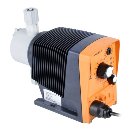
Overview of the Device and Control Elements 5 Overview of the Device and Control Elements 5.1 Overview of the Device P_BE_0013_SW Fig. 2: Complete overview Control unit Drive Unit Liquid End P_BE_0008_SW Fig. 3: Overview of liquid end (PV) Discharge valve Backplate Dosing head Bleed valve... -
Page 17: Control Elements
Overview of the Device and Control Elements 5.2 Control Elements P_BE_0011_SW Fig. 4 Pulse Control Switch Stroke Length Adjustment Knob Fault indicator (red) Warning indicator (yellow) Operating indicator (green) Multifunctional Switch "External Control" Terminal Relay connection (optional) "Level Switch" Terminal 5.2.1 Pulse Control Switch In the Extern Contact operating mode, either a series of strokes can be triggered or an inbound series of contacts can be stepped down... -
Page 18: Functional And Fault Indicators
Overview of the Device and Control Elements 5.2.4 Functional and Fault Indicators Fault indicator (red) The fault indicator lights up if the fluid level in the chemical feed container falls below the second switching point of the level switch (20 mm residual filling level in the chemical feed container). This LED flashes in the event of an undefined operating mode. -
Page 19: Functional Description
Functional Description 6 Functional Description 6.1 Liquid End The dosing process is performed as follows: The diaphragm is pressed into the dosing head; the pressure in the dosing head closes the suction valve and the feed chemical flows through the discharge valve out of the dosing head. -
Page 20: Functions
Functional Description 6.6 Functions The functions are described below in the "Operation" chapter. 6.7 Relays The pump has two connector options. Fault indicating relay option The relay can close a connected power circuit, in the event of for an alarm buzzer, in the event of fault or warning indicating alerts, such as a level warning. -
Page 21: Electrical Installation
Electrical Installation 7 Electrical Installation WARNING! Risk of electric shock There may be live voltage in the inside of the pump. – Disconnect the mains cable on the pump from the mains power supply before working on it. WARNING! Risk of electric shock This pump is supplied with a grounding conductor and a grounding-type attachment plug. -
Page 22: Description Of The Terminals
Electrical Installation 7.2 Description of the Terminals 7.2.1 "External Control" Terminal The "external control" terminal is a five-pole panel terminal. It is compatible with two- and four-pole cables. The "Auxiliary Frequency" function can only be used with a five-pole cable. Electrical interface for pin 1 "Pause"... -
Page 23: Level Switch" Terminal
Electrical Installation 7.2.2 "Level Switch" Terminal A 2-stage level switch with pre-warning and end switch-off can be connected. Electrical interface Specification Value Unit Voltage with open contacts Input resistance 10 kΩ Activation via zero volt connection contact (load: 0.5 mA at 5 V) or semi-conductor switch (residual voltage <... -
Page 24: Output For Other Relays (Identity Code 4 + 5)
Electrical Installation Identity code 1 + 3 To pin VDE cable Contact CSA cable white NO (normally open) white green NC (normally closed) brown C (common) black Identity code 4 + 5 To pin VDE cable Contact Relays yellow NO (normally open) Fault indi‐... - Page 25 Electrical Installation To pin VDE cable Contact Relays yellow NO (normally open) Fault indi‐ cating relay green C (common) Fault indi‐ cating relay white NO (normally open) Pacing relay brown C (common) Pacing relay...
-
Page 26: Operation
Operation 8 Operation 8.1 Manual Personnel: Instructed personnel 8.1.1 Capacity The capacity is determined by the stroke length and the stroke rate. The stroke length is adjusted by the stroke length adjustment knob within a range of 0 ... 100 %. A stroke length of between 30 ... 100 % (SEK type: 50 ... -
Page 27: Extern Contact
Operation 8.1.3 Extern Contact "Extern" operating mode: In the Extern Contact operating mode, either a series of strokes can be triggered or an inbound series of contacts can be stepped down via the pulse control switch by a single contact on the "External control"... -
Page 28: Maintenance
Maintenance 9 Maintenance WARNING! It is mandatory that you read the safety information and specifications in the "Storage, Transport and Unpacking" chapter prior to shipping the pump. CAUTION! Warning of feed chemical spraying around Feed chemical can spray out of the hydraulic compo‐ nents if they are manipulated or opened due to pressure in the liquid end and adjacent parts of the system. - Page 29 Maintenance Liquid ends with bleed valve: Interval Maintenance task Personnel Quarterly* In addition: Technical personnel Check that the bypass line is fixed firmly to the liquid end Check that the bleed valve is tight Check the discharge and bypass line for kinks Check that the bleed valve is operating correctly * under normal loading (approx.
-
Page 30: Repair
Danger of an electric shock Unauthorised repairs inside the pump can result in an electric shock. For this reason repairs inside the pump may only be performed by a ProMinent branch or representative, in particular the following: – Replacement of damaged mains connection lines –... - Page 31 Repair Cleaning a discharge valve or a suction valve on types (PP, PV, NP) 1000, NOTICE! 1601, 1602, 1604, 2504 – Discharge and suction valves differ from each other! Only take them apart one after each other, so that you do not confuse the components! –...
-
Page 32: Replacing The Diaphragm
Repair 10.2 Replacing the Diaphragm WARNING! A few cubic centimetres of feed chemical may have accumulated behind the diaphragm in the backplate following a leak - depending on the design! – Take this feed chemical into consideration when you are planning a repair - especially if it is hazardous! Personnel: Technical personnel If necessary take protective measures. - Page 33 Repair NOTICE! The diaphragm must be screwed exactly onto the drive shaft otherwise the pump will subsequently not dose correctly! Unscrew the diaphragm (3) again. Place the backplate (4) onto the pump housing (6). NOTICE! – The leakage hole must point downwards when the pump is later installed - Fig.
- Page 34 Repair P_BE_0018_SW Fig. 12: Exploded view of liquid end...
-
Page 35: Troubleshooting
Troubleshooting 11 Troubleshooting Safety information WARNING! Warning of hazardous or unknown feed chemical Should a hazardous or unknown feed chemical be used, it may escape from the hydraulic components when working on the pump. – Take appropriate protective measures before working on the pump (protective eyewear, protective gloves, ...). -
Page 36: Fault Alerts
Personnel Yellow LED indicator (warning The fluid level in the feed tank has Fill the feed tank Instructed indicator) lights up reached "low liquid level stage 1" personnel 11.4 All Other Faults Please contact the responsible ProMinent branch or representative! -
Page 37: Decommissioning
Decommissioning 12 Decommissioning Decommissioning WARNING! Danger from chemical residues There is normally chemical residue in the liquid end and on the housing after operation. This chemical residue could be hazardous to people. – It is mandatory that the safety information relating to the "Storage, Transport and Unpackaging"... - Page 38 For Germany: The cleaned used parts can be disposed of at munic‐ ipal waste collection points. Should you be unable to locate a munic‐ ipal waste collection point - ProMinent head office will take back the cleaned used parts at a small charge - providing that they are covered...
-
Page 39: Technical Data
Technical Data 13 Technical Data 13.1 Performance Data Beta ® b operating at 180 strokes/ minute and 100 % stroke length Type Minimum flow rate Minimum flow rate Connec Suction Priming Maximu tor size lift* lift** at maximum counter pres‐ at medium counter pressure priming sure... - Page 40 Technical Data Type Minimum flow rate Minimum flow rate Connec Suction Priming Maximu tor size lift* lift** at maximum counter pres‐ at medium counter pressure priming sure äÆ x iÆ pres‐ sure on suction side m WS m WS stroke stroke 1001 0.72...
-
Page 41: Accuracy
Technical Data 13.2 Accuracy 13.2.1 Standard Liquid End Specification Value Unit Capacity range of the series -5 ... +10 % * Reproducibility ±2 % ** * - at max. stroke length and max. operating pressure for all mate‐ rial versions ** - at constant conditions and min. -
Page 42: Material Data
Technical Data 13.4 Material Data Standard liquid ends Version Dosing Suction/ Seals Valve balls head Discharge connector Polypropy‐ Polypropy‐ EPDM Ceramic lene lene Polypropy‐ Polypropy‐ Ceramic lene lene Polypropy‐ PVDF PTFE Ceramic lene Acrylic EPDM Ceramic glass Acrylic Ceramic glass Acrylic PVDF PTFE... -
Page 43: Ambient Conditions
Technical Data Version: 100 - 230 V ±10 %, 50/60 Specification Value Unit Hz, Beta ® / 5b Power rating, approx. 19 ... 21 W Current I eff 0.71 ... 0.28 A Peak current 5.9 ... 2.3 A Switch on peak current (within approx. 15 A 50 ms decaying) Fuse*... -
Page 44: Climate
Technical Data NPT liquid end Specification Value Unit Max. temperature long-term at max. 45 °C operating pressure Max. temperature for 15 min at max. 2 60 °C Minimum temperature -10 °C PVT liquid end Specification Value Unit Max. temperature long-term at max. 45 °C operating pressure Max. -
Page 45: Compatibility
Technical Data Safety requirements Degree of protection: 1 - mains power connection with protective earth conductor 13.8 Compatibility Some hydraulic parts of the Beta b are identical to those of the ® Beta a, gamma/ L and delta ® ® There is most compatibility with pumps of the Beta ®... -
Page 46: Appendix
Appendix 14 Appendix 14.1 Dimensional Drawings Dimensional drawing of Beta ® b, PP material version 10.85 41 / 36 10 / 15 92 / 102 81 / 85 131.5 / 135.5 P_BE_0019_SW Fig. 13: Dimensional drawing of Beta ® BT4b/BT5b, PP material version - dimensions in mm 1000 - 1604 0708 - 0220 1008 - 0420... - Page 47 Appendix Dimensional drawing of Beta b, NP ® material version 12.9 41 / 36 10 / 15 92 / 102 81 / 85 131.5 / 135.5 P_BE_0020_SW Fig. 14: Dimensional drawing of Beta BT4b/BT5b, NP material version - dimensions in mm ®...
- Page 48 Appendix Dimensional drawing of Beta b, PV ® material version 29.3 41 / 36 10 / 15 92 / 102 81 / 85 131.5 / 135.5 P_BE_0022_SW Fig. 16: Dimensional drawing of Beta ® BT4b/BT5b, PV material version - dimensions in mm 1604 0708 - 0220 1008 - 0420...
- Page 49 Appendix Dimensional drawing of Beta b, TT ® material version 41 / 36 10 / 15 92 / 102 81 / 85 131.5 / 135.5 P_BE_0024_SW Fig. 18: Dimensional drawing of Beta BT4b/BT5b, TT material version - dimensions in mm ®...
-
Page 50: Diagrams For Setting The Capacity
Appendix 14.2 Diagrams for Setting the Capacity BT4b 1602 C [l/h] f [%] BT4b 1000 C [l/h] f [%] 180 min 90 min 180 min 90 min 162 min 72 min 162 min 72 min 144 min 54 min 144 min 54 min 126 min 36 min... - Page 51 Appendix C [l/h] BT4b 0708 f [%] C [l/h] BT4b 0220 f [%] 180 min 90 min 180 min 90 min 72 min 72 min 162 min 162 min 144 min 54 min 144 min 54 min 126 min 36 min 126 min 36 min 108 min...
- Page 52 Appendix BT5b 1008 C [l/h] BT5b 0420 f [%] C [l/h] f [%] 180 min 90 min 180 min 90 min 72 min 162 min 72 min 162 min 144 min 54 min 54 min 144 min 126 min 36 min 126 min 36 min 108 min...
-
Page 53: Exploded Views Of Liquid Ends
Appendix 14.3 Exploded Views of Liquid Ends Beta ® 1000 - 1604 PP liquid end with bleed valve P_BE_0038_SW Fig. 23: Beta 1000 - 1604 PP liquid end with bleed valve ® Pos. Description Type 1000 Type 1601 Type 1602 Type 1604 Connector kit 6/4 PVT 1023246 1023246... - Page 54 Appendix Beta 0708 (1008) - 0220 (0420) PP ® liquid end with bleed P_BE_0039_SW Fig. 24: Beta 0708 (1008) - 0220 (0420) PP liquid end with bleed ® Pos. Description Type 0708 Type 0413 Type 0220 (1008) (0713) (0420) Connector kit 8/5 PVT 1023247 1023247 1023247...
- Page 55 Appendix Beta 0232 PP liquid end without ® bleed valve P_BE_0034_SW Fig. 25: Beta 0232 PP liquid end without bleed valve ® Pos. Description Type 0232 Connector kit 12/9 PVT 1023248 4 Valve balls 404281 Discharge valve, compl. 9.2-2 PVT 1023125 Diaphragm 1000251...
- Page 56 Appendix Beta 1000 - 1604 NP liquid end with ® and without bleed valve P_BE_0035_SW Fig. 26: Beta 1000 - 1604 NP liquid end with and without bleed valve ® Pos. Description Type 1000 Type 1601 Type 1602 Type 1604 Connector kit 6/4 PVT 1023246 1023246...
- Page 57 Appendix Beta 0708 (1008) - 0220 (0420) NP ® liquid end with and without bleed valve P_BE_0036_SW Fig. 27: Beta 0708 (1008) - 0220 (0420) NP liquid end with and without bleed valve ® Pos. Description Type 0708 Type 0413 Type 0220 (1008) (0713)
- Page 58 Appendix Beta 0232 NP liquid end with and ® without bleed valve P_BE_0037_SW Fig. 28: Beta 0232 NP liquid end with and without bleed valve ® Pos. Description Type 0232 Connector kit 12/9 PVT 1023248 4 Valve balls 404281 Discharge valve, compl. 9.2-2 PVT 1023125 Diaphragm 1000251...
- Page 59 Appendix Beta 1000 - 1604 PV liquid end with ® bleed valve P_BE_0032_SW Fig. 29: Beta 1000 - 1604 PV liquid end with bleed valve ® Pos. Description Type 1000 Type 1601 Type 1602 Type 1604 Connector kit 6/4 PVT 1035660 1035660 1035660...
- Page 60 Appendix Beta 0708 (1008) - 0220 (0420) PV ® liquid end with bleed valve P_BE_0033_SW Fig. 30: Beta 0708 (1008) - 0220 (0420) PV liquid end with bleed valve ® Pos. Description Type 0708 Type 0413 Type 0220 (1008) (0713) (0420) Connector kit 8/5 PVT 1035661...
- Page 61 Appendix Beta 0232 PV liquid end without ® bleed valve P_BE_0034_SW Fig. 31: Beta 0232 PV liquid end without bleed valve ® Pos. Description Type 0232 Connector kit 12/9 FVD PVT 1035659 4 Valve balls 404281 Discharge valve, compl. 9.2-2 PVT 1023125 Diaphragm 1000251...
- Page 62 Appendix Beta 1604 - 0220 (0420) PV HV liquid ® end, for highly viscous feed chemicals P_BE_0047_SW Fig. 32: Beta 1604 - 0220 (0420) PV HV liquid end, for highly viscous feed chemicals ® Pos. Description Type 1604 Type 0708 Type 0413 Type 0220 Connector kit DN10 HV with PVT tube nozzle 1017405 1017405...
- Page 63 Appendix Beta 1000 - 1604 TT liquid end ® P_BE_0029_SW Fig. 33: Beta 1000 - 1604 TT liquid end ® Pos. Description Type 1000 Type 1601 Type 1602 Type 1604 Connector kit 6/4 TTT 817201 817201 817201 817201 4 Valve balls 404201 404201 404201...
- Page 64 Appendix Beta 0708 (1008) - 0220 (0420) TT ® liquid end P_BE_0030_SW Fig. 34: Beta 0708 (1008) - 0220 (0420) TT liquid end ® Pos. Description Type 0708 Type 0413 Type 0220 (1008) (0713) (0420) Connector kit 8/5 TTT 817204 817204 817204 4 Valve balls...
- Page 65 Appendix Beta 0232 TT liquid end ® P_BE_0031_SW Fig. 35: Beta 0232 TT liquid end ® Connector kit 12/9 TTT 817202 Diaphragm 0232 1000251 Spring, special accessory Safety membrane 1027414 4 Valve balls 404281 Suction valve compl. TTT 809445 Discharge valve compl. TTT 809444 Pos.
- Page 66 Appendix Beta 1000 - 1604 SS liquid end ® P_BE_0026_SW Fig. 36: Beta 1000 - 1604 SS liquid end ® Pos. Description Type 1000 Type 1601 Type 1602 Type 1604 Connector kit 6 mm SS 104233 104233 104233 104233 4 Valve balls 404201 404201 404201...
- Page 67 Appendix Beta 0708 (1008) - 0220 (0420) SS ® liquid end P_BE_0027_SW Fig. 37: Beta 0708 (1008) - 0220 (0420) SS liquid end ® Pos. Description Type 0708 Type 0413 Type 0220 (1008) (0713) (0420) Connector kit 8 mm SS 817204 817204 817204...
- Page 68 Appendix Beta 0232 SS liquid end ® P_BE_0028_SW Fig. 38: Beta 0232 SS liquid end ® Pos. Description Type 0232 Connector kit 12 mm SS 104245 4 Valve balls 404281 Discharge valve compl. 12 mm SST 809446 Diaphragm 1000251 Safety diaphragm 1027414 Suction valve compl.
- Page 69 Appendix Beta 1601 - 1604 PP SEK and 1601 ® - 1604 NP SEK liquid end, self-bleeding P_BE_0041_SW Fig. 39: Beta 1601 - 1604 PP SEK and 1601 - 1604 NP SEK liquid end, self-bleeding ® Pos. Part Material Part no. version 1, 9, 10 Connector kit 6/4...
- Page 70 Appendix Pos. Part Material Part no. version Connector kit 8/4 With 2504: 791161 Connector kit 6/4 With 2504: 817065 Connector kit 6/4 4 Valve balls 404201 Bleed valve 1001063 Bleed valve 1001062 Bleed valve 1001061 Bleed valve 1001060 Discharge valve 1001067 compl.
- Page 71 Appendix Spare parts kits for Material version Part no. type: 1601 1001660 1602 1001661 1604 without spring 1035337 1604 with spring 1035333 1601 1001666 1602 1001667 1604 without spring 1035338 1604 with spring 1035334 Seal sets Material Part no. 1 Seal set EPDM 1001674 1 Seal set...
- Page 72 Appendix Beta 0708 (1008) - 0220 (0420) ® PP / NP SEK liquid end, self-bleeding P_BE_0040_SW Fig. 40: Beta 0708 (1008) - 0220 (0420) PP / NP SEK liquid end, self-bleeding ® Pos. Part Material Part no. version Connector kit 6/4 817160 Connector kit 6/4 817173...
- Page 73 Appendix Pos. Part Material Part no. version Connector kit 12/9 817175 Connector kit 12/9 790577 Connector kit 12/9 817067 4 Valve balls 404201 Bleed valve 1001063 Bleed valve 1001062 Bleed valve 1001061 Bleed valve 1001060 Discharge valve 1001071 compl. Discharge valve 1001070 compl.
-
Page 74: Ordering Information
Appendix Spare parts kits for Material version Part no. type: 0708 (1008) 1001669 0413 (0713) 1001670 0220 (0420) 1001671 Seal sets Material Part no. 1 Seal set EPDM 1001674 1 Seal set 1001672 The positions listed are included in the spare parts kit. We reserve the right to make technical modifications. -
Page 75: Retrofitting Relays
RC Gate, 0.22 µF / 220 Ω: 710802 Further sources of information Further information on spare parts, accessories and options can be found in: the exploded drawings the identity code the "General Operating Instructions on ProMinent solenoid ® dosing pumps". the ProMinent ® Equipment catalogue 14.5 Retrofitting Relays... - Page 76 Appendix Personnel: Technical personnel Materials: Screwdriver 8 x 1.5 (mm) Torx wrench Philips head screwdriver The pump is hydraulically and electrically clamped. It is fixed well. Push the screwdriver into the slot opening. ð The screwdriver must be placed almost at the base of the slot opening and lie solidly against its sides.
- Page 77 Appendix P_BE_0046_SW Fig. 42: Fitting the relay board The pump is factory-programmed to "fault indicating relay (NC)" and - if fitted - "pacing relay (NO)". Should another switching function be required, the pump can be reprogrammed in the Heidelberg head office. Retrofit relay kit for Beta ®...
-
Page 78: Declaration Of Conformity
Appendix 14.6 Declaration of Conformity Fig. 43: EC Declaration of Conformity for Beta BT4b and BT5b ®... -
Page 79: Safety Declaration Form
______________________ ____ _____ ____ _____ _________ _________ _______ _____ ______________________ ____ _____ ____ _____ _________ _________ _______________ _ _____ _ __ _ _________________________ _ ________ _________ _______ _ ________ _ ________ _ _______ y l l Fig. 44: ProMinent Declaration of No Objection ®... -
Page 80: Index
Index 15 Index " "External Control" Terminal....17, 18, 22, 26 Hierarchy of Operating Modes......20 "Level Switch" Terminal......... 17, 18 Humidity............... 44 About this Pump............. 9 Identity Code............6 Accuracy.............. 41 Inductive Consumers........... 21 Air humidity............44 Information in the event of an emergency.... 12 Ambient Conditions.......... - Page 81 Index Replacing the Diaphragm........32 Suction valve............16 Reproducibility.......... 19, 26, 41 Supply Voltage............. 21 Safety Chapter............. 10 Technical Data............. 39 Safety requirements..........44 Temperatures............43 Scope of delivery..........15 Test (function).......... 17, 20, 26 SEK types............19 Transport.............. 14 Self-Bleeding............
Need help?
Do you have a question about the Beta BT4b and is the answer not in the manual?
Questions and answers