ABB RVC Installation And Operating Instructions Manual
Power factor controllers
Hide thumbs
Also See for RVC:
- Quick start (2 pages) ,
- Installation and operating instructions manual (27 pages)
Table of Contents
Advertisement
Advertisement
Table of Contents

Related Manuals for ABB RVC


Summary of Contents for ABB RVC
- Page 1 Installation and Power Factor Controllers Operating Instructions...
-
Page 2: Table Of Contents
Table of contents Page Read this first ............4 About this Instruction Manual . -
Page 3: Read This First
This Instruction Manual is designed to help you quickly install and operate the RVC Controller. Before installation and operation of the RVC Controller, read this notice carefully. Keep it at the disposal of people in charge of installation, maintenance and operation. -
Page 4: Figures
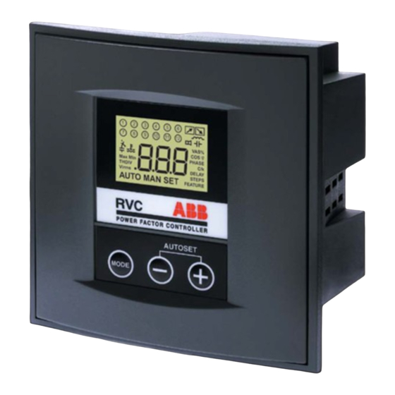
2. Figures Fig.1. Front view LCD Display Keypad C / k Mounting brackets... - Page 5 Fig.2. Rear view Voltage connection inputs Curent connection unputs ' + ' ' + ' & & ' - ' ' - ' Mounting brackets l g i Mounting brackets Step outputs...
- Page 6 Fig.3. LCD display and keypad A. LCD Display 6. Demand for switching on or 1. Activated outputs off capacitor steps 2. Inductive PF 7. Numerical display 3. Capacitive PF 8. Programmable parameters 4. Undercompensation alarm 9. Modes 5. Overtemperature indication PHASE DELAY OUTPUT...
-
Page 7: Mounting
3. Mounting Slide the Controller (1) into the Capacitor Bank cubicle (2) C /k... - Page 8 2. A. Insert the Mounting Brackets (3) in the corresponding Fixation Holes (4) of the Controller 2. B. Pull the Mounting Brackets backwards.
- Page 9 Turn the Screw (7) into the '+ ' '+ ' & & '- ' '- ' Mounting Brackets (3) and tighten until the Controller is fixed lg iu lg iu...
-
Page 10: Connection Arrangement
4. Connection arrangement Wiring diagram k, l: leads of the current transformer NETWORK SUPPLY LOAD L2, L3: 2 of the 3 phases (not monitored by the CT) M1, M2: leads of the normally closed contact output relay common source 1-12: outputs Leads connection 1. -
Page 11: Switching Strategy
• to use a longer switching delay time and as a result, to reduce the number of switchings. On the basis of the reactive power demand measured during the switching delay time, the RVC identifies the number of steps to be switched on. It then automatically switches the bigger outputs first to avoid unnecessary intermediary switchings. -
Page 12: Programmable Parameters
MAN Mode • Steps are switched on and off manually by pressing + and - buttons ϕ • The LCD display shows the actual cos AUTO SET Mode Automatic setting of the following parameters: • C/k: automatic setting of the sensitivity •... - Page 13 The value can be set either automatically (AUTO SET) or manually (MAN SET – C/k). Phase shift If the RVC is connected as shown on the connection diagram of the PF Controller, the phase shift is 90° (default setting). For special connections, please refer to chapter 10 – Programming.
-
Page 14: Operation Of The User Interface
8. Operation of the user interface... -
Page 15: Easy Commissioning
9. Easy Commissioning Step 1. Energize the PF Controller Note: If you have a short-circuit on the CT’s secondary winding AUTO do not forget to open it after having connected the current input of the PF Controller. After a power outage, the reset delay time is 40 seconds. During this delay time, the alarm icon blinks and the alarm contact remains closed. - Page 16 Step 4. Press the Mode button once to ϕ activate the manual setting of the target cos The already programmed value is displayed. If the RVC has never been programmed before, 1.00 appears on the LCD display. MAN SET...
- Page 17 During this procedure, the values of the parameters automatically set in the previous step will be displayed. All parameters are also programmable manually (see chapter 11). Once in AUTO Mode, the RVC automatically switches on the ϕ necessary steps to reach the programmed target cos ϕ...
-
Page 18: Manual Operation
10. Manual Operation In the AUTO Mode, press on the Mode button once to activate the MAN Mode Switching on or off is done manually by pressing on the + or – button. respectively indicate the demand to switch on or off one step is being processed. - Page 19 2. C/k The programmed C/k value is displayed. The recommended setting of C/k can be calculated by the following formula or can be read directly in the table here after. Three-phase network: Single phase network: Q: reactive 3-phase power of one step Q: reactive power of one step (kvar) (kvar) U: system voltage (V)
- Page 20 3. Phase The programmed phase value is displayed. The phase shift to be programmed can be selected from the tables below. Three-phase connection (Phase to phase) Voltage is measured between L2 and L3. CT Connection Connection Drawing Phase to be programmed Direct Inverted Direct...
- Page 21 Three-phase connection (Phase to neutral) Voltage is measured between L1 and Neutral. CT Connection Connection Drawing Phase to be programmed Direct L2 L3 Inverted L2 L3 Direct Inverted Direct Inverted...
- Page 22 1.2.8 The output value may be programmed as 1:1:2:2:2:…:2 1.1.2 follows: 1:1:2:4:4:…:4 1.1.4 RVC 3: up to 3 RVC 6: up to 6 1:1:2:4:8:…:8 1.1.8 RVC 8: up to 8 RVC 10: up to 10 RVC 12: up to 12...
-
Page 23: Auto Setting
11. B. Auto-setting of parameters The AUTO SET Mode offers three submenus: 1. setting of C/k, phase, output and sequence 2. setting of C/k and phase 3. setting of output and sequence To select the AUTO SET mode – submenu 1, use the Mode button as represented on the flow chart p.8. - Page 24 To start the automatic setting, press the + and – buttons simultaneously AU starts flashing. The indicated parameters are then automatically set. During this procedure which may take several minutes, the PHASE capacitor steps are activated. OUTPUT AUTO SEQUENCE The setting procedure is finalized once AU stops flashing.
-
Page 25: Alarm - Temperature
80°c and the temperature icon then disappears. AUTO Alarm contact The RVC is also fitted with a normally closed alarm contact. It is closed each time: ϕ 1. The target cos is not reached 6 minutes after all outputs have been switched on. -
Page 26: Testing And Troubleshooting
13. Testing and troubleshooting Testing B. Inductive load ϕ After installation of the automatic capacitor 1. Set desired cos bank and programming of the switching 2. Select AUTO Mode parameters, the following tests can be Capacitor steps will now be automatically performed depending on load situation. - Page 27 Troubleshooting ϕ Fault: The controller does not switch If the average cos over a period of time is ϕ on or off steps although there is a too low, the preset cos may be increased. considerable variable inductive load. Fault: All capacitors are switched on Solution although the required reactive power is relatively low.
- Page 28 RVC error messages during an Autoset Message Description Recommended action Check that the CT short-circuit bridge Current too small is removed and start the Autoset again Re-start the Autoset procedure under Phase not found after 10 trials. more stable conditions.
- Page 29 Message Description Recommended action Check connections, Phase error : closest value is 180°. capacitors and fuses he controller could not find a known configuration Check connections, F-10 Phase error : closest value is 210°. capacitors and fuses The controller could not find a known configuration Check connections, F-11...
- Page 30 Message Description Recommended action Re-start the Autoset procedure under F-18 Sequence not found after 10 trials. more stable conditions. The load is varying too quicly. Check connections, F-19 Unknown sequence. capacitors and fuses The controller could not find a known sequence.
-
Page 31: Electromagnetic Compatibility
14. Electromagnetic compatibility This PF Controller has been verified for compliance with EU (European Union) directives for EMC (electromagnetic compatibility) for operation at 50Hz and bears the CE marking to this effect. When an apparatus is used in a system, EU directives may require that the system be verified for EMC compliance. -
Page 32: Technical Specifications
• automatic measurement of C/k. Insensitivity to harmonics. 220V to 240V, 380V to 440V Number of outputs: depending on type of PF Controller. RVC 3: 3 Working with generative and Voltage tolerance: RVC 6: 6 regenerative loads (four-quad- +/- 10% on indicated operating RVC 8: 8 rant operation). - Page 33 While all care has been taken to ensure that the information contained in this publication is correct, no responsibility can be accepted for any inaccuracy. We reserve the right to alter or modify the information contained herein at any time in the light of technical or other developments.