Table of Contents
Advertisement
Chapter 1 General Introduction....................................................................................................3
1.1 Summary.............................................................................................................................3
1.2 Product List.........................................................................................................................3
1.3 Environmental Condition................................................................................................... 3
1.4 specification........................................................................................................................ 5
1.4.1 display specification.....................................................................................................5
1.4.2 PLC specification......................................................................................................... 5
1.4.3 Appearance................................................................................................................7
1.4.4 Dimension................................................................................................................. 8
Chapter 2 PLC Introduction......................................................................................................... 8
2.1 Functions.............................................................................................................................8
2.1.1 CPU Status and LEDs.................................................................................................. 8
2.1.2 USB Programming port................................................................................................9
2.1.3 Serial Communication Port........................................................................................10
2.1.4 High Speed Counter and High Speed Pulse Output.................................................. 10
2.1.5 Edge Interrupts........................................................................................................... 10
2.1.6 Data Retentive and Data Backup............................................................................... 10
2.1.7 Real-time Clock (RTC).............................................................................................. 11
2.1.8 Backup Battery...........................................................................................................12
2.2 Wiring diagram................................................................................................................. 12
2.3 Dimension.........................................................................................................................14
2.4 Technical Specification.....................................................................................................14
Chapter 3 Software Introduction................................................................................................16
3.1 HMI programming............................................................................................................16
3.1.1 Create project............................................................................................................. 16
3.1.2 Edit configuration ...................................................................................................19
3.1.3 download link for HMI manual.............................................................................. 19
CONTENT
Kinco-MK
User Manual
1
Advertisement
Table of Contents

Related Manuals for Kinco MK Series


Summary of Contents for Kinco MK Series
-
Page 1: Table Of Contents
Kinco-MK User Manual CONTENT Chapter 1 General Introduction....................3 1.1 Summary..........................3 1.2 Product List.........................3 1.3 Environmental Condition....................3 1.4 specification........................5 1.4.1 display specification.....................5 1.4.2 PLC specification......................5 1.4.3 Appearance........................7 1.4.4 Dimension......................... 8 Chapter 2 PLC Introduction......................8 2.1 Functions..........................8 2.1.1 CPU Status and LEDs....................8 2.1.2 USB Programming port....................9... - Page 2 Kinco-MK User Manual 3.2 PLC........................... 20 3.2.1 introduction........................ 20 3.2.2 Install driver of USB programming port..............20 3.2.3 High speed counter.....................32 3.2.3.1 Operation Modes and Inputs of the High-speed Counters........33 3.2.3.2 Control Byte and Status Byte..................34 3.2.3.3 Preset value (PV value) setting................36 3.2.3.4 “CV=PV”...
-
Page 3: Chapter 1 General Introduction
Kinco MK series accords with GB/T 15969.3-2007 (idt IEC61131-2: 2007)standard and test specifications. The following table lists the conditions and requirements for MK series to work properly. It is the user's responsibility to ensure that the service conditions are not exceeded. - Page 4 Kinco-MK User Manual Transport and storage temperature -10℃~+60℃ Ambient relative 10%~95%, no condensation conditions humidity Altitude Up to 3000 m Mechanical within manufacturer's original packaging, 5 falls from 1m Free falls conditions of height. Normal Operation Open equipment : -10 --- +55°C; Enclosed equipment: 0~...
-
Page 5: Specification
128MB Flash + 64MB DDR2 RAM Recipe memory 256KB+RTC Expansion memory 1 USB Host Programming download 1*USB Slave/Ethernet/USB Flash disk Printer port DTools programming + EdgeAccess for remote services + Kinco Software Miot for IoT function 1.4.2 PLC specification Parameters MK070E-33DT Power supply Rated voltage DC24V DC20.4V-28.8V... - Page 6 Kinco-MK User Manual Digital IO DI 16*DC24V,DO 14*Transistor AI2*IV, AO 1*IV(Supports voltage and current type) Analog IO Expansion Up to 8 module;Support KS series expansion module Programming port USB2.0 Slave 2*RS485, PORT1&PORT2, Baudrate up to 115.2kbps. Port 1:Support programing, Modbus RTU master and slave,Free...
-
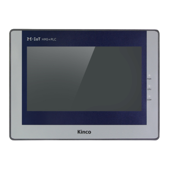
Page 7: Appearance
Kinco-MK User Manual Interrupt 2,0.1ms time base. Counter Yes. The difference is less than 5min/month at 25℃. 1.4.3 Appearance Display and touch Indicator light DC24V 2*RS485 Ports Ethernet Port (HMI) USB Host and EX. (PLC) Clear Program (PLC) USB Programming... -
Page 8: Dimension
Kinco-MK User Manual 1.4.4 Dimension MK070E-33DT Dimension 204*150*38.55mm Cutout size 192*138mm Chapter 2 PLC Introduction 2.1 Functions 2.1.1 CPU Status and LEDs The CPU has two modes: STOP mode and RUN mode. In RUN mode, the CPU executes the main scan cycle and all interrupt tasks.In STOP mode, the CPU only process communication requests which comes from KincoBuilder software and other Modbus RTU master device.At the same time, all output points are immediately output... -
Page 9: Usb Programming Port
Windows. When the first time using USB cable to download Program on MK series.The USB driver is needed installation.The installation step please refer to Kinco HPbuilder [Help]-[User... -
Page 10: Serial Communication Port
Kinco-MK User Manual 2.1.3 Serial Communication Port MK070E providing 2*RS485 COM,which is Port1 and Port2,the Baudrated up to 115.2Kbps. Port1 could use as programming port,as well as Modbus RTU Master/Slave protocol,and free communication. Port2 could use as Modbus RTU Master/Slave protocol,free communication. -
Page 11: Real-Time Clock (Rtc)
Kinco-MK User Manual battery (Replaceable but un-rechargeable) for data retentive. When CPU loses power, the data in the RAM will be maintained by the lithium battery, and the retentive ranges will be left unchanged at next power on.Through [Hardware] configuration in KincoBuilder, user can select the type of data retentive (Such as V,C area) and the range. -
Page 12: Backup Battery
Kinco-MK User Manual The HMI real time (RTC) funcation can provide real-time time/calendar,user can change RTC from the system Setting , or through register LW10000 - LW10006 to modify time. MK070E RTC can be kept after power off.If precise time is required, user also can set HMI RTC synchronization with PLC CPU. - Page 13 Kinco-MK User Manual MK070E-33DT...
-
Page 14: Dimension
Kinco-MK User Manual 2.3 Dimension MK070E 2.4 Technical Specification DI Specifications Input type Source/Sink Rated input voltage DC 24V (Max. 30V) Rated input current 3.5mA@24VDC Max input voltage of logic 0 5V@0.7mA Common channel:11V@2.0mA Minimum input voltage of logic 1... - Page 15 Kinco-MK User Manual Common channel: 15μs; channel: Input filter time delay 10μs(50k) · off-to-on Common channel: 60μs; HSC channel: 6μs · on-to-off (50k) Isolation between input and internal circuit Opt-electrical isolation · Mode 500VAC/1 min · Voltage DO Specifications(Transistor type)
-
Page 16: Chapter 3 Software Introduction
Current mode:Maximum 500Ω Output resistance Voltage mode :Minimum 10KΩ Chapter 3 Software Introduction 3.1 HMI programming HMI programming software: Kinco DTools. Download link for HMI software http://en.kinco.cn 3.1.1 Create project Process to create project based on Kinco DTools. 1, create project Open Kinco DTools 1.1 create new project... - Page 17 Drag “Serial port”in 【Graph element window】--【Connector】 to construct window. ②Choose device—choose HMI type Drag “MK070E”in 【Graph element window】--【HMI】to construct window. System will show ”Display Mode”, we can choose “Horizontal” or “Vertical” Click 【OK】 ③choose device—choose PLC type(communication protocol) Drag “Kinco PLC series” in 【Graph element window】to construct window...
- Page 18 Kinco-MK User Manual 1.3 connect devices Drag “COM” of HMI to close left side of connector, until connector and “COM” move together. Connect PLC and serial port with same way. 1.4 parameters setup-HMI Double click HMI, it will appearance 【HMI Atrribute】...
-
Page 19: Edit Configuration
Kinco-MK User Manual HMI COM0 setting 3.1.2 Edit configuration . Reference Kinco DTools manual. 3.1.3 download link for HMI manual https://en.kinco.cn/Download/D_enUserManual/HMI/Kinco%20DTools%20User%20Manual. -
Page 20: Plc
6.zip 3.2.2 Install driver of USB programming port MK series provide USB programming port. This programming port will be used as virtual serial port in PC. Its driver files are located in \drivers in Kincobuilder installation folder. Right now it supports Windows XP、Windows 7、Windows 8 and Windows 10 systems, as shown in... - Page 21 Kinco-MK User Manual path and install the driver again. Copy mdmcpq.inf to C:\WINDOWS\INF. Copy usbser.sys to C:\WINDOWS\SYSTEM32\DRIVERS\ How to install driver in Windows 8,Windows10 ? 1、If you can use internet,Win8/Win10 will update driver automatically .
- Page 22 Kinco-MK User Manual...
- Page 23 Kinco-MK User Manual 2、If you have not internet, pls reference below information. Below picture is advanced starting of Win8 Find advanced starting, then choose 7 to forbid driver signature. (1) Install PLC drive according Window guidance. Choose driver files in Win8.
- Page 24 Kinco-MK User Manual...
- Page 25 Kinco-MK User Manual It will show “settings” when mouse at the right side of Window, then click “settings” (2)...
- Page 26 Kinco-MK User Manual Click “update and recovery” in the “PC settings” (3)...
- Page 27 Kinco-MK User Manual (4)Click “restart now” at advanced startup...
- Page 28 Kinco-MK User Manual (5)Click advanced options (6)click startup settings...
- Page 29 Kinco-MK User Manual (7) Click restart...
- Page 30 Kinco-MK User Manual (8) This is the picture after computer restarting. Choose 7 to forbid driver signature inforcement, then PC restart. (9)Re-install PLC driver based on Window guidance. Choose driver files in the Win8 It will show below information, choose “ install this driver software anyway”...
- Page 31 Kinco-MK User Manual...
-
Page 32: High Speed Counter
Kinco-MK User Manual 3.2.3 High speed counter MK070E-33DT provides 4 high speed counters (HSC0~HSC3).High speed counter supports a variety of modes, it can be single-phase, dual-phase (Up/Down), AB phase (1-fold and 4-fold frequency).The maximum counting frequency of the four pulse counters is 50KHz. -
Page 33: Operation Modes And Inputs Of The High-Speed Counters
Kinco-MK User Manual 3.2.3.1 Operation Modes and Inputs of the High-speed Counters Input signals of high-speed counter include: clock (input impulse), direction, start and reset. In different operation modes input signals is different. Please see below: Description I0.1 I0.0 I0.5... -
Page 34: Control Byte And Status Byte
Kinco-MK User Manual HSC 3 Mode Description I0.6 I0.7 Single-phase up/down counter Clock with internal direction control:SM127.3 A/B phase quadrature counter Clock A Clock B 3.2.3.2 Control Byte and Status Byte Control Byte In SM area,each high-speed counter is assigned control byte to save its configuration data: one control word (8 bit), current value and pre-set (double-integer with 32 bit). - Page 35 Kinco-MK User Manual Preset value comparison interrupt (“CV=PV”) cyclic execution. SM141.2 SM151.2 SM161.2 SM171.2 0=No. 1=Yes. Note:Only valid when preset value is relative value. SM141.3 SM151.3 SM161.3 SM171.3 Reserved Update multiple PV segment and preset SM141.4 SM151.4 SM161.4 SM171.4 value:0=No. 1=Yes SM141.5...
-
Page 36: Preset Value (Pv Value) Setting
Current PV segment No.(Start from 0) 3.2.3.3 Preset value (PV value) setting MK series support up to 32 PV value for each high speed counter, and supports setting PV value as relative value or absolute value. It supports “CV=PV” interrupt cyclic execution. - Page 37 Kinco-MK User Manual (1) All the offset value are the offset bytes related to the table. (2) When it is set as relative value,then the absolute value of PV data must be greater than 1,or PLC will consider the segment of multiple PV finish and count the number of PV according to this(Higher priority than setting quantity of PV).
-
Page 38: Cv=Pv" Envent No
Kinco-MK User Manual If SM141.0 is 1,it means “CV=PV” interrupt is cyclic execution.When the last PV interrupt finishes execution,PLC will take the current counting value as reference to calculate new value for PV interrupt,then it will start to compare the counting value and execute “CV=PV”... -
Page 39: How To Use High Speed Counter
Kinco-MK User Manual 3.2.3.5 How to use high speed counter Method 1:Use instructions for programming 1)Configure the control byte of HSC and define the current value (i.e. starting value) and the preset value. 2)Use HDEF instruction to define the counter and its operation mode. -
Page 40: How To Use High Speed Pulse Output
Kinco-MK User Manual How to use HSC wizard: 1) Select the counter in【HSC】. 2) Check【Enable HSC】, and then continue following configuration. 3) Select counter mode in【Mode】. 4) Select the starting mode in【Start method】. There are two starting method: “Using HSC instruction”: If selecting this method, then it needs to execute HSC instruction to start the HSC. -
Page 41: High Speed Pulse Output Instruction
Kinco-MK User Manual Q0.0 Q0.1 Q0.4 Q0.5 Position output channel Q0.2 Q0.3 Q0.6 Q0.7 Position enable control bit SM201.3 SM231.3 SM251.3 SM221.3 Position output channel output motor position signal. Forward is 0, rollback is 1. Position output enable control bit forbid or allow the involved output channel. The position enable control bit have highest priority. -
Page 42: High-Speed Pulse Output Function Of Hmi-Plc
IL If CR is 1,then PLS is executed. It won’t influence the value of CR. 3.2.4.2.1 High-speed Pulse Output Function of MK series MK070E provides 4 PTO/PWM pulse generators that can be used to output PTO/PWM. Therefore, one generator is assigned to Q0.0, called PWM0 or PTO0; the second one is assigned to Q0.1, called PWM1 or PTO1, the third one is assigned to Q0.4,called PWM2 or... - Page 43 Kinco-MK User Manual instructions, then the PTO/PWM generator controls the output and prohibits the normal use of this output channel. Some registers are provided in SM area for each PTO/PWM generator. When user needs to use high speed pulse output function, it needs to configure these memories, and then executes PLS instruction to implement desired operation of PTO/PWM.
-
Page 44: Pto/Pwm Register
Kinco-MK User Manual In this mode, the starting address of the profile table is stored in SMW168 (corresponding to PTO0), SMW178(corresponding to PTO1), SMW218(corresponding to PTO2) and SMW248(corresponding to PTO3).Time base is configured by SM67.3 (corresponding to PTO0) ,SM77.3 (corresponding to PTO1),SM97.3 (corresponding to PTO2) and SM107.3 (corresponding to PTO3). - Page 45 Kinco-MK User Manual SM67.3 SM77.3 SM97.3 SM107.3 PTO/PWM Time base: 0=1μs;1=1ms Update method: SM67.4 SM77.4 SM97.4 SM107.4 0 = asynchronous update; 1 = synchronous update Operation mode: SM67.5 SM77.5 SM97.5 SM107.5 0 = single segment; 1 = multiple segment SM67.6 SM77.6...
-
Page 46: Pto Operations
Kinco-MK User Manual Whether the cycle time or pulse number of PTO is wrong: 0=No, 1=Yes SM66.4 SM76.4 SM96.4 SM106.4 Note: Cycle time and pulse number must be greater than 1. PTO profile terminated due to user command: SM66.5 SM76.5 SM96.5 SM106.5... - Page 47 Kinco-MK User Manual Execute the PLS instruction to configure PTO0 and start it. Changing the PTO Cycle Time (Single-Segment Operation) Follow these steps to change the PTO cycle time. Set control byte SMB67 according to the desired operation. For example, SMB67 = B#16#81 indicates: ...
-
Page 48: Pwm Operations
Kinco-MK User Manual Enable the PTO/PWM function Select PTO operation Select multi-segment operation Select 1μs as the time base Set an odd number as the starting position of the profile table into SMW168. Use V area to configure the profile table. -
Page 49: How To Use Position Control Instructions
Control Registers and Status Registers For the Position Control instructions,Kinco-K2 specifies a control byte for each high-speed output channel to store its configurations. Besides, it assigns a current value register(DINT) to store the pulse number which has outputted currently (This value will increase when run forward and decrease when run reverse).The following table describes the control byte and the... - Page 50 Kinco-MK User Manual Read/Write. Emergency-Stop bit. If this bit is 1, no position control instructions can be executed. SM201.7 SM231.7 SM251.7 SM221.7 When executing the PSTOP instruction, this bit is set to 1 automatically, and it must be reset in the program..
- Page 51 Kinco-MK User Manual Following takes channel 0 as example to describe how to reset current value. (* Network 0 *) (*Based on homing signal, when it moves to homing, it requires to clear current value*) %SM0.0 PHOME 0, %M0.0, %M0.1, %M0.2, %VW0, %VW2, %VW4, %VD6, %VW10, %M0.4, %M0.5, %M (* Network 1 *) (*After PHOME finishing, it uses finishing bit “DONE”...
-
Page 52: Can It Change Maximum Output Frequency When Position Control Instruction Is
Kinco-MK User Manual %SM201.4 3.2.5.2 Can it change maximum output frequency when position control instruction is executing? PREL(Relative position)and PABS(Absolute position) will not change maximum output frequency when it is executing. It will read the parameters minimum frequency, maximum frequency and acceleration/deceleration time parameters when it starts, and calculates suitable acceleration/deceleration segments according to the value of these parameters, then it will start outputting pulse. - Page 53 Kinco-MK User Manual CPU AI area from expansion CAN. Then user programming can visit it. All the signal types have detection range. If the value is over range, the modules will warn, Meanwhile it will send problem file to CPU by expansion module. Pls connect all the channels that is not used, also setup signal type to 【0-10V】,then these channels won’t...
-
Page 54: Configuration In Software
Kinco-MK User Manual 0-20mA 0-20.4mA 1-5V 0.96-5.1V V×1000 0-10V 0-10.2V 3.3.3 Configuration in software Hardware configuration in the software can be used to configure analog channel parameters. Address • The starting address : Specifies the start byte address that the module occupies in the address space in the AI region(That's the address of the first channel). - Page 55 Kinco-MK User Manual Channel Settings Signal form : Select the type of input signal for each channel. The sample values are automatically converted linearly within the CPU, The data conversion format please refer to 3.3.2 Measurement Ranges and The measured value Representation ...
Need help?
Do you have a question about the MK Series and is the answer not in the manual?
Questions and answers