ABB CP600 Series Operating Instruction
Hide thumbs
Also See for CP600 Series:
- Operating instructions manual (29 pages) ,
- System manual (119 pages) ,
- Operating instructions manual (28 pages)

Related Manuals for ABB CP600 Series


Summary of Contents for ABB CP600 Series
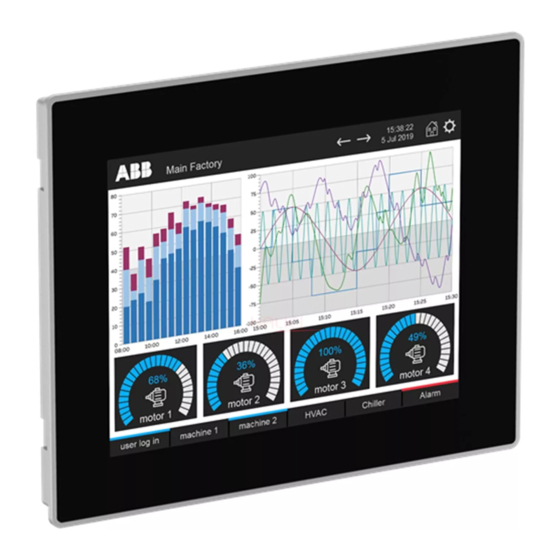
- Page 1 — O P E R AT I N G I N S T R U C T I O N Control Panels CP600 2nd generation CP6407, CP6410, CP6415...
-
Page 2: Table Of Contents
Contents 1 Introduction ........................... 3 2 Safety guide ........................... 4 Safety guide ..........................4 Safety notices ........................... 4 Markups ............................. 5 3 Product overview .......................... 6 4 Standards and approvals ......................7 Product identification ......................7 5 Technical specifications ....................... 9 6 Technical data.......................... -
Page 3: Introduction
CO NT R O L PA NE L S CP6 00 2N D G EN ER AT I ON Introduction The operational guidelines described below are information on device technical data, installation, transportation, storage, assembly, use and maintenance. The Manual refers to the following models: Picture Type Description... -
Page 4: Safety Guide
Safety guide Safety guide The manual contains safety standards that must be respected for the personal safety and to avoid damage. Indications of attention are divided into three levels of severity. Safety notices Indicates an imminent risk. It will lead to death or serious injury if not avoided. -
Page 5: Markups
CO NT R O L PA NE L S CP6 00 2N D G EN ER AT I ON Markups Enumeration. Precondition for an operation instruction or a description. Operation instruction with one step. Operation instruction with several steps. ... -
Page 6: Product Overview
They have been designed to offer competitive price/performance ratio for challenging indus- trial applications where robust devices are a requirement. These products feature a full die-cast aluminum housing. Compatibility with CP600 series cut-out offers an easy upgrade path for the old series. -
Page 7: Standards And Approvals
CO NT R O L PA NE L S CP6 00 2N D G EN ER AT I ON Standards and approvals The products have been designed for use in an industrial environment in compliance with the 2014/30/EU EMC Directive. The products have been designed in compliance with: EN 61000-6-4 EN 61000-6-2... - Page 8 Information on type plate (example) Description Product model name CP6407 Product part number 1SAP540710R0001 Serial number S.N.: AAxxxxxxxxxxxxxxxxAA Product version ID V.: xxxxxxxxxxxxxxx Manufacturer address ABB Automation Products GmbH Eppelheimer Straße 82, 69123 Heidelberg Germany 3ADR010470, 2, en_US...
-
Page 9: Technical Specifications
CO NT R O L PA NE L S CP6 00 2N D G EN ER AT I ON Technical specifications Resistive Touchscreen technology 3 V 50 mAh Lithium, rechargeable, not user-replaceable, Back-up battery model VL2330. Fuse Automatic Serial port RS-232, RS-485, RS-422 software configurable Flash 4 GB... - Page 10 Voltage dips, short Port: DC mains; Level: EN 61000-4-29 interruptions and voltage 0% duration: 10 ms 20 spaces by 1 s variations immunity test Test executed on the 24 VDC of the EUT Durability information Backlight service life 40000 hr. or more (LED type) (Time of continues operation until the brightness of the backlight reaches 50 % of the rated value when the ambient...
-
Page 11: Technical Data
CO NT R O L PA NE L S CP6 00 2N D G EN ER AT I ON Technical data Model CP6407 CP6410 CP6415 Display TFT Color / LED TFT Color / LED TFT Color / LED Colors Resolution 800X480 800X600 1024X768... -
Page 12: Dimensions
Dimensions CP6407 147,5 mm 187,5 mm 176 mm 136 mm 40 mm 5.80” 7.38” 6.92” 5.35” 1.57” CP6410 276 mm 221 mm 40 mm 232,5 mm 287,5 mm 10.86” 8.70” 1.57” 9.15” 11.31” CP6415 381 mm 296 mm 45 mm 307,5 mm 392,5 mm 15”... -
Page 13: Installation Environment
CO NT R O L PA NE L S CP6 00 2N D G EN ER AT I ON Installation environment Avoid prolonged exposition to direct sunlight to avoid the risk of overheating the device. The equipment is not intended for installation in contact with corrosive chemical compounds. Check the resistance of the front panel to a specific compound before installation. -
Page 14: Safety Instruction
Safety instruction For all installation notes, please refer to the Installation Instruction provided with the product. CAUTION! Installation procedure Place the fixing brackets contained in the fixing kit as shown in figure. Tightening torque: 130 Ncm or screw each fixing screw until the bezel corner gets in contact with the panel. -
Page 15: Connections
CO NT R O L PA NE L S CP6 00 2N D G EN ER AT I ON Connections CP600 2nd generation 1. Serial port 2. Ethernet Port 0 3. Ethernet Port 1 4. USB Port V2.0, max. 500 mA 5. -
Page 16: Serial Port
Serial port The serial port is used to communicate with the PLC or with another type of controller. Different electrical standards are available for the signals in the PLC port connector: RS-232, RS-422, and RS-485. The serial port is software programmable. Make sure you select the appropriate interface in the programming software. -
Page 17: Power Supply, Grounding And Shielding
CO NT R O L PA NE L S CP6 00 2N D G EN ER AT I ON Power supply, grounding and shielding The power supply terminal block is shown in the figure below. Description +24 V DC (L+) Common (M) Ground 3 conductors 1,5 mm... - Page 18 All the electronic devices in the control system must be properly grounded. Grounding must be performed according to applicable regulations. 3ADR010470, 2, en_US...
-
Page 19: Battery
CO NT R O L PA NE L S CP6 00 2N D G EN ER AT I ON Battery CP600 2nd generation panels are equipped with rechargeable Lithium battery, not user-re- placeable. The hardware real-time clock (date and time) is maintained by the battery. At the first installation, CP600 2nd generation panels shall be charged for 48 hours. -
Page 20: Special Instruction For Use
Special instruction for use • Install the HMI device according to the accompanying installation instructions. • Ground the HMI device according to the accompanying installation instructions. • Only qualified personnel may install the HMI device or repair it. • Ensure that the aeration holes are not covered. •... -
Page 21: System Settings
CO NT R O L PA NE L S CP6 00 2N D G EN ER AT I ON System settings CP600 2nd generation control panels have a system settings interface to allow configuration of system options. The user interface of System Settings is based on HTML pages accessible locally on CP600 or in remote using a Web browser Chrome v44 or higher on port 443 (https://IP/machine_config). - Page 22 Activation of System Settings in System Mode: Normal operation If PB610 runtime is not running: Press “System Setting” button on the CP600 2nd generation screen to enter in System Settings in User Mode. Select “Restart” → “Config OS” to reboot in System Mode. If PB610 runtime is running: recall context menu and select “System Settings”.
-
Page 23: Unpacking And Packing Instructions
CO NT R O L PA NE L S CP6 00 2N D G EN ER AT I ON Unpacking and packing instructions To repack the unit, please follow the instructions backwards. NOTE CP600 2nd generation, 2, en_US... - Page 24 With regard to purchase orders, the agreed particulars shall prevail. ABB AG does not accept any responsibility whatsoever for potential errors or possible lack of information in this document. We reserve all rights in this document and in the subject matter and illustrations contained therein.
Need help?
Do you have a question about the CP600 Series and is the answer not in the manual?
Questions and answers