
Related Manuals for Moog System 15


Summary of Contents for Moog System 15
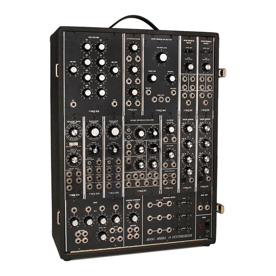
- Page 1 Instruction Manual MOOG Synthesizer System 15 Introduction • Module Functions • Initial Setup • Basic Definitions • Instructional Sequences •...
- Page 2 We of Moog Music, Inc. have applied our capabilities and expe- rience to give you an instrument that will serve you well in your music producing and teach- ing activities.
-
Page 3: Module Functions
MODULE FUNCTIONS 921A Oscillator Driver Allows one set of control voltages to determine the pitch and rectangular waveform widths of the 921B’s. 921B Oscillator Produces the basic waveforms for audio or control purposes, with expanded facilities for modulation and synchronization. 921 Oscillator Produces the basic repetitive waveforms for audio and control purposes, with expanded fa- cilities for triggered waveform clamping and waveform level variation. -
Page 4: Initial Setup
INITIAL SETUP Set the synthesizer on a table 27 to 29 inches high, at least 24 inches deep. Avoid placement near drafts, direct sunlight, heaters and the like. For permanent installation, put a 5 inch plat- form (or the keyboard cover) under the module cabinet to allow easy accessibility to the con- trols and jacks at the bottom. -
Page 5: Basic Definitions
BASIC DEFINITIONS Here are some definitions of terms that we will use: VOLTAGE: An electrical quantity analogous to pressure. SIGNAL: A voltage variation that carries information. Signals are carried between modules by PATCH CORDS. An AUDIO signal varies rapidly enough to be discernable by the human ear. - Page 6 Patching rules: Connect outputs to inputs. To "split" a signal for feeding to two or more inputs, patch from the output to be split to the MULTIPLE. The remaining MULTIPLE jacks are now outputs. Combine module outputs with a MIXER. Control signals may not be patched into the audio signal path.
- Page 7 INSTRUCTIONAL SEQUENCES This section contains instructional sequences designed to give you "hands on" familiarity with the basic patching procedure of the Synthesizer 15. Think of each set of interconnecting patches as a map that provides a clear graphic indication of the signal flow paths. You will quickly discover that the control settings are of paramount importance in determining the na- ture of the resultant sound material.
- Page 8 A. THE AUDIO GENERATORS 907A 904A 8’ 921A 921B 921B MIXER CONTROLLERS TRUNK 1. Turn on the power switch. This supplies power to the entire instrument. Turn all controls and switches to the positions shown in the drawing. Turn on the monitor amplifier. 2.
- Page 9 B. USING THE KEYBOARD TO DETERMINE PITCH 907A 904A 8’ 921A 921B 921B MIXER CONTROLLERS TRUNK 1. Patch from the RECTANGULAR output of a 921B OSCILLATOR to a SIGNAL INPUT on the 902 VOLTAGE CONTROLLED AMPLIFIER, and from a SIGNAL OUTPUT on a 902 VOLTAGE CONTROLLED AMPLIFIER to TRUNK LINE 1.
- Page 10 C. USING THE KEYBOARD TO ARTICULATE THE SOUND The audio generators are always on. In order to articulate tones, a 902 VOLTAGE CON- TROLLED AMPLIFIER is used in conjunction with a 911 ENVELOPE GENERATOR. 907A 904A 8’ 921A 921B 921B MIXER CONTROLLERS TRUNK...
- Page 11 When triggered (key depressed), the 911 output voltage rises in a time, T1. At the end of its rise, the output voltage immediately falls with a characteristic time, T2, to a sustaining level, Esus. When the key is released, the output voltage falls to zero with characteristic time, T3. T1, T2, T3, and Esus are individually controllable by means of the 911 front panel controls.
- Page 12 D. USING BOTH 921B OSCILLATORS AND THE 921 VOLTAGE CON- TROLLED OSCILLATOR Control signals fed to the 921A OSCILLATOR DRIVER have the same effect on each 921B OSCILLATOR. A control signal fed to a FREQUENCY control input jack raises and lowers the frequencies of both 921B OSCILLATORS so the pitch interval between them remains constant.
- Page 13 E. FILTERS Four filters are included with the Synthesizer 15. The 907 FIXED FILTER BANK consists of ten separate sections, each with its own attenuator. Eight of these sections cover frequency bands approximately one-half octave each. The center frequencies are indicated by the large numbers above the appropriate attenuator knobs.
- Page 14 3. Turn off the MIXER control A and turn up MIXER controls B and C. Obtain any desired interval between the 921B OSCILLATORS by varying the FREQUENCY and RANGE con- trols. Play the keyboard. 4. Manipulate the FIXED CONTROL VOLTAGE, RANGE, and REGENERATION controls of the 904A LOWPASS FILTER;...
- Page 15 F. USE OF TWO ENVELOPE GENERATORS AND THE REVERSIBLE ATTENUATOR The Synthesizer 15 has two 911 ENVELOPE-GENERATORS. The voltage contour pro- duced by a 911 may control the frequency (when patched to a 921), amplitude (when patched to the 902), or filtering (when patched to the 904A) of an audio signal. With two envelope voltages, it is possible to control two audio signals, or two aspects of a single audio signal.
- Page 16 G. THE 921 VOLTAGE CONTROLLED OSCILLATOR When the COARSE RANGE switch is in the AUDIO position, the 921 VOLTAGE CON- TROLLED OSCILLATOR is similar in operation to one 921A OSCILLATOR DRIVER and one 921B OSCILLATOR. The audio waveform out jacks are in the bottom row. 907A 904A 8’...
- Page 17 waveform. Vary the FREQUENCY control and the WAVEFORM switch of the 921. Return the WAVEFORM switch to ??? and the 921 FREQUENCY control to 0. 6. Remove the plug from the 921A FREQ control input to the 921A WIDTH control input. Notice that the width, instead of frequency, of the 921B rectangular waveform is being con- trolled.
- Page 18 H. THE 921 VOLTAGE CONTROLLED OSCILLATOR CLAMPING POINT The CLAMPING POINT section of the 921 VOLTAGE CONTROLLED OSCILLATOR al- lows the waveform to be brought abruptly, or "clamped", to a manually selected point in its cycle at the onset of a trigger signal. 907A 904A 8’...
- Page 19 I. SYNCHRONIZATION OF OSCILLATORS The 921B OSCILLATORS have inputs and switches for synchronizing their outputs with ex- ternal signals whose frequencies are harmonically related. The external input signal is called the synchronizing signal, while the 921B output is called the synchronized signal. One 921B may provide the synchronizing signal, or some other oscillator, such as the 921, may be used to synchronize both 921B’s.
- Page 20 The left 921B produces the second subharmonic while the right 921B produces the third sub- harmonic. Listen carefully while varying the settings of the FREQUENCY and RANGE con- trols on the 921B’s. You will hear the tones go in and out of synchronization.
- Page 21 J. MODULATION OF THE OSCILLATOR BANK The 921A-921B oscillator bank contains three sets of frequency control inputs. The set on the 921A is labelled FREQUENCY. Control signal changes fed to these inputs affect both 921B’s equally. Furthermore, a given control signal change at the 921A FREQUENCY con- trol input will result in corresponding frequency ratio change (or musical interval change) at the outputs of the 921B’s.
- Page 22 3. Now move the patchcord from the FREQUENCY control input to the DC MODULATE input on the left 921B. 4. Play the keyboard. Notice that only the pitch of the left 921B goes up and down in re- sponse to the 911’s output. 907A 904A 4’...
- Page 23 K. 995 ATTENUATORS PANEL The 995 ATTENUATORS PANEL provides the capability of attenuating, or lessening the magnitude of up to three signals. The panel provides three separate attenuators when all input jacks are used. However, the inputs are arranged in a top-to-bottom hierarchy which permits a signal placed in the upper or middle input to appear at one or both lower inputs.
Need help?
Do you have a question about the System 15 and is the answer not in the manual?
Questions and answers