Table of Contents
Advertisement
Advertisement
Table of Contents

Related Manuals for Moog Matriarch


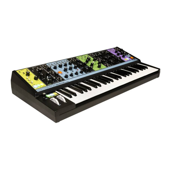
Summary of Contents for Moog Matriarch
- Page 4 — Consult the dealer or an experienced radio/TV technician for help. CAUTION: Please note that any changes or modifications made to this product not expressly approved by Moog Music Inc. could void the user’s authority granted by the FCC to operate the equipment.
-
Page 5: Table Of Contents
TABLE OF CONTENTS UNPACKING & INSPECTION SETUP & CONNECTIONS ABOUT MATRIARCH SIGNAL FLOW FEATURES & CONTROLS KEYBOARD LEFT-HAND CONTROLLER OSCILLATORS UNDERSTANDING OSCILLATOR SYNC OSCILLATOR PATCH POINTS MIXER MIXER PATCH POINTS FILTERS FILTER PATCH POINTS ENVELOPE GENERATORS (ADSR) ENVELOPE GENERATOR PATCH POINTS... - Page 6 4’ 8’ 4’ 8’ 4’ 16’ 2’ 16’ 2’ 16’ 2’ 16’ 2’ 200Hz 2kHz 20Hz 20kHz Based on the vintage circuitry of classic Moog synthesizer modules, Matriarch is a catalyst for creative ideas and a medium for multidimensional expression.
-
Page 7: Unpacking & Inspection
Supply POWER Plug the included power adapter into the 12V DC power jack on the back of your Matriarch. Plug the other end of the included power adapter into an AC outlet. Matriarch uses a universal power supply that operates with power sources from 100 Volts to 240 Volts AC; 50/60 Hz. -
Page 8: About Matriarch
In addition to its standalone function, Matriarch is also an ideal processor of external sound sources and a powerful keyboard front-end for expanding a DFAM, Mother-32, Grandmother, or Eurorack modular system. -
Page 9: Signal Flow
Each module is equipped with a set of 3.5mm patch points that can be utilized to create new audio and control pathways within Matriarch. These patch points can also be used to establish synchronization and interconnectivity with other Moog synthesizers like Mother-32, DFAM, and Grandmother, or to create a completely a new instrument through deep integration with a Eurorack modular system. -
Page 10: Left-Hand Controller
LEFT-HAND CONTROLLER The Left-Hand Controller (LHC) is home to a number of performance-enriching controls. The PITCH (Pitch Bend) and MOD (Modulation) wheels deliver real-time expression, while the GLIDE knob provides enhanced articulation between notes. The Left-Hand Controller is also home to the Transport Buttons for the Arpeggiator and Sequencer, allowing instant access to these powerful features during performance. - Page 11 NOTE: Unlike the PITCH wheel, the MOD wheel is not spring-loaded, and will remain in position until it is moved again. TIP: You can patch from the MOD WHL OUT jack on the Matriarch rear panel to any available destination for a more expressive and expansive performance.
-
Page 12: Oscillators
NOTE: There is a FINE TUNE knob located on Matriarch’s rear panel for adjusting the overall tuning of the instrument. MODULE PROVENANCE: Matriarch’s Oscillators are based on those found in the Minimoog Voyager and are descendants of the classic Moog 921 Oscillator design. OCTAVE 8’... -
Page 13: Understanding Oscillator Sync
OSCILLATORS (Continued) FREQUENCY (Oscillators 2, 3, & 4) The FREQUENCY knob detunes each oscillator from the pitch of Oscillator 1 over a range of +/- 7 semitones (or a musical 5th). The center position (12 O’clock) tunes the oscillator in unison with Oscillator 1. Increasing the value (+) raises the pitch, while decreasing the value (–) lowers the pitch. - Page 14 OSCILLATORS (Continued) 3 SYNC Pressing this button (On/lit red) will cause Oscillator 3 to become sync’d to Oscillator 2. In this case, changing the Frequency of Oscillator 3 will vary the degree of the Sync effect and its associated harmonic content. The range of the FREQUENCY knob is also greatly increased while the oscillator is sync’d.
-
Page 15: Oscillator Patch Points
PULSE WIDTH AMT knob in the Modulation module and listen to how modulating this waveform affects the sound. OSCILLATOR PATCH POINTS Each Matriarch oscillator is equipped with versatile patch points, allowing for a variety of modulation possibilities, including Linear FM (Frequency Modulation) and PWM (Pulse Width Modulation). -
Page 16: Mixer
CV / AUDIO OUTPUT: 10V peak-to-peak MIXER The Mixer is where all of the sound sources within Matriarch are blended together before being passed on to the Filter. Patch points in the Mixer allow each hardwired source (Oscillators 1 – 4 and Noise) to be replaced with an external audio signal. - Page 17 MIXER (Continued) NOISE Matriarch features a built-in White Noise generator. Noise is an unpitched sound source that can be a useful tool for creating powerful percussion sounds, or for adding a gentle breath to synthesized wind instruments such as flutes.
-
Page 18: Mixer Patch Points
Mixer with an external sound source, such as a Eurorack oscillator or other electronic music devices. TIP: Matriarch’s Mixer is DC coupled, which means it can also be used to sum multiple control voltages. Combining audio signals with control signals will yield results that can be unique, bizarre, or completely undesirable. -
Page 19: Filters
Matriarch’s filters operate in one of three selectable modes; Series, Parallel, or Stereo. Depending on the current setting of the FILTER MODE switch, VCF 1 has... - Page 20 FILTERS (Continued) CUTOFF Matriarch’s CUTOFF knob specifies the Filter Cutoff frequency for both 200Hz 2kHz VCF 1 and VCF 2 in a linked fashion. The SPACING knob is used to offset the frequency of VCF 1, above or below the Cutoff Frequency of VCF 2.
- Page 21 FILTERS (Continued) RESONANCE 1 & 2 Resonance channels a portion of the Filter’s output back to the input of the Filter, creating an emphasis peak at the Filter’s Cutoff frequency. This is useful for adding focus, funkiness, or “sci-fi laser blasts” to a sound. The RESONANCE 1 knob sets the amount of Resonance being applied to VCF 1, while the RESONANCE 2 knob sets the amount of Resonance being applied to VCF 2.
-
Page 22: Filter Patch Points
VCF 1 OUT The audio output of VCF 1 is available via this jack, allowing it to be sent to any input on Matriarch itself, or to an external electronic music device. AUDIO OUTPUT: 10V peak-to-peak NOTE: VCF 1 can be used as a stand-alone audio processor. - Page 23 FILTERS (Continued) CUTOFF 1 IN A control signal connected here will modulate the Cutoff frequency of VCF 1. This is based on the current CUTOFF, SPACING, ENVELOPE AMT, and KB TRACKING knob settings. CV INPUT: -5V to +5V CUTOFF 2 IN A control signal connected here will modulate the Cutoff frequency of VCF 2.
-
Page 24: Envelope Generators (Adsr
Some sounds end just as quickly, and some linger like a held chord on a piano. We call this the envelope of a sound. Matriarch uses a pair of identical Envelope Generators to create control voltages that also change over time. This type of control voltage can be applied to the amplitude of the sound, changing its volume over time. - Page 25 ENVELOPE GENERATORS (ADSR) (Continued) DECAY The DECAY knob determines the amount of time required for the control signal to fall from the maximum level achieved by the Attack stage to the Sustain level as the key is held. The DECAY knob has a range from 2 milliseconds to 10 seconds.
-
Page 26: Envelope Generator Patch Points
A Gate or Control Voltage > 2.3V connected to this input can be used to initiate the Filter Envelope Generator as well. NOTE: Patching into the TRIGGER IN jack will override Matriarch’s Keyboard Gate connection to the EG. CV / GATE INPUT: 0V to +8V... - Page 27 A Gate or Control Voltage > 2.3V connected to this input can be used to initiate the Amplitude Envelope Generator as well. NOTE: Patching into the TRIGGER IN jack will override Matriarch’s Keyboard Gate connection to the EG.
-
Page 28: Output
EG. Instead, the output level is set by a default voltage normalled to the VCA 1 CV IN and VCA 2 CV IN patch points. NOTE: Matriarch will continue to drone at this level, whether a key is held or not. -
Page 29: Vca Patch Points
OUTPUT (Continued) VCA PATCH POINTS All of the VCA patch points are inputs. The upper row (VCA 1 IN and VCA 2 IN) are audio inputs, while the second row (VCA 1 CV IN and VCA 2 CV IN) are control signal inputs. - Page 30 OUTPUT (Continued) VCA 2 CV IN A control signal connected here will determine the output level of VCA 2. Normally, this control signal comes from the Amplitude Envelope Generator. With the VCA MODE switch set to ENV or SPLIT, this jack can accept an -8V to +8V signal that will control the level of the signal at the input of VCA 2.
-
Page 31: Stereo Delay
This will result in noisy or “lo-fi” delay trails that may or may not be desirable. NOTE: When Matriarch is sync’d to an internal or external clock, rotating the TIME knob will adjust the delay time in divisions or multiplications of the clock rate (BPM). - Page 32 The balance between the output of the VCAs and the output of the Stereo Delay is controlled by the MIX knob, acting as a crossfader between the two signals before the combined signal is sent to Matriarch’s many audio outputs. In the fully counterclockwise position, there is no Stereo Delay signal present in the MAIN OUTPUTS.
-
Page 33: Stereo Delay Patch Points
STEREO DELAY (Continued) STEREO DELAY PATCH POINTS The Stereo Delay module features both Audio and Control signal inputs. The Audio inputs override and replace the normal hardwired audio connections. The Control inputs are summed with the current value of their corresponding panel knobs. NOTE: Additional Stereo Delay patch points are located on the rear panel. - Page 34 STEREO DELAY (Continued) MIX IN The value of a Control signal connected to this input will be summed with the current position of the MIX knob to determine the balance between the dry (unprocessed) audio signal, and the wet (processed) audio signal. CV INPUT: -5V to +5V TIME 1 IN A Control signal connected to this input will modulate the delay time of...
-
Page 35: Modulation
MODULATION Modulation is a vital facet of synthesizer performance and sound design. In short, whenever one signal is used to change the value of another– it is known as modulation. Modulation can come from a number of sources– the Envelope Generators, Keyboard Tracking, an audio Oscillator (FM), or a dedicated Modulation oscillator such as the one found here. - Page 36 Using this three-position switch, the amount of Pitch Modulation set using the PITCH AMT knob (above) can be assigned to all of the Matriarch oscillators, to Oscillators 1 & 3 only, or to Oscillators 2 & 4 only. The latter two options can be extremely useful in the 2-Note Paraphonic mode.
-
Page 37: Modulation Patch Points
MODULATION (Continued) MODULATION PATCH POINTS Control signals connected to the RATE IN and SYNC IN patch point jacks can set the rate and reset the starting point of the Modulation oscillator. In addition, three patch point output jacks deliver Noise, S/H (Sample and Hold), and the selected Wave as control sources that can be used to modulate any controllable parameter. - Page 38 MODULATION (Continued) S/H OUT (Continued) TIP: A control or gate signal received at the SYNC IN jack will reset the Modulation oscillator to the beginning of its wave cycle, meaning the Sample and Hold feature can be stepped by an external trigger or gate. Try patching from the GATE OUT jack in the ARP / SEQ module to the SYNC IN jack, and set the RATE knob to its minimum value.
-
Page 39: Utilities (1
UTILITIES (1) Matriarch is equipped with two Utilities modules. Each is filled with an assortment of tools that are key to the exploration of modular synthesis. A signal can be split and sent to multiple locations, multiple signals can be merged together, and individual signals can be attenuated and inverted. - Page 40 UTILITIES (1) (Continued) INPUT Any audio or control signal connected to this jack will be fed into the Attenuator. CV/AUDIO INPUT: -8V to +8V NOTE: An 8-Volt DC source is normalled to the input of each Attenuator. With nothing connected to the INPUT jack, a voltage is present at the Attenuator’s OUTPUT jack that is based on the position of the ATTENUATOR knob, and any control signal applied to the Attenuator CV IN jack.
-
Page 41: Utilities (2
UTILITIES (2) Matriarch is equipped with two Utilities modules. Each is filled with an assortment of tools that are key to the exploration of modular synthesis. A signal can be split and sent to multiple locations, multiple signals can be merged together, and individual signals can be attenuated and inverted. - Page 42 CV INPUT: -8V to +8V PATCHABLE LFO This LFO (Low Frequency Oscillator) provides Matriarch with a patchable modulation source separate from the Modulation oscillator. Two waveforms, Triangle and Square, are available simultaneously, and the rate of the LFO can be modulated via control voltage.
- Page 43 This is useful for creating swooping cascades of notes, building a rhythmic base, or for generating new and fun musical ideas. Matriarch allows you to select the order in which the notes are played, and also provides the option of repeating the pattern in different octaves.
- Page 44 20 – 280 BPM (Beats Per Minute). The accompanying LED flashes at the current Rate setting. If Matriarch is sync’d to MIDI, External Clock, or Tap Tempo, the RATE knob will select timing values that are musical subdivisions of this external tempo.
- Page 45 ARP / SEQ (Continued) DIRECTION The DIRECTION switch selects the order in which arpeggiated or sequenced notes are played. The same setting may have a different result based on whether the Arpeggiator or Sequencer is active. ORD (Order) ARPEGGIATOR Arpeggiated notes will play in the same order they were originally played on the keyboard.
- Page 46 BANK 3 is chosen as the sequence source. SEQUENCE Matriarch provides a total of 12 sequence locations across three user-selectable Banks. This four-position SEQUENCE knob is used to select one of the four available sequences within the currently selected Bank as the active sequence.
-
Page 47: Arp / Seq Patch Points
ARP / SEQ (Continued) REST, TIE, RATCHET (Continued) Press the green TIE button to enter a Tie for the current sequence step. A Tie is used to string two or more individual sequence steps together as if they were played legato-style. The green TIE button will stay lit until the next step is entered into the sequence. -
Page 48: Arp / Seq Lhc Controls
ARP / SEQ (Continued) VELOCITY OUT The control signal available at this output is based on the Velocity of the notes entered into the Arpeggiator or Sequencer with the keyboard. CV OUTPUT: 0V to +5V (0V to +10V selectable via Global Settings) CV OUT The control voltage available at this output jack is the same used to specify the pitch of the Oscillators being played by the Arpeggiator or Sequencer. -
Page 49: Paraphony
The VOICE MODE switch and the MULTI TRIG (Multiple Trigger) button determine the behavior of the Matriarch sound engine when more than one key is played on the keyboard at the same time. Matriarch can be played as a monophonic, 2-note paraphonic, or 4-note paraphonic analog instrument. - Page 50 ARP / SEQ (Continued) VOICE MODE The VOICE MODE switch selects whether Matriarch will play as a 1-Voice monophonic synthesizer, as a 2-Note paraphonic synthesizer, or as a 4-Note paraphonic synthesizer. 1 (One-Note Monophonic) In this mode, all four oscillators are played from a single key on the keyboard.
-
Page 51: Rear Panel
Matriarch’s rear panel expands the instrument as a powerful tool for interconnective expression. Process external sound sources, grow your Moog semi-modular family, or control a Eurorack modular system with ease. -
Page 52: Audio Jacks
REAR PANEL The rear panel of your Matriarch is populated with various audio, control, MIDI and USB jacks, as well as a global fine turning knob, power switch, the DC power connection jack, and a Kensington security slot. FINE TUNE ±... - Page 53 INSTRUMENT IN A monaural audio signal from another instrument (guitar, drum machine, synthesizer, etc.) can be connected to Matriarch via this 1/4” input. An audio signal applied to this input is then fed directly into the Mixer module to be processed along with the onboard audio sources.
-
Page 54: Stereo Delay Jacks
REAR PANEL (Continued) STEREO DELAY JACKS The STEREO DELAY section of the rear panel relates to the operation and control of the Stereo Delay. Other jacks and controls for the Stereo Delay are found on the front panel. DELAY OUTS The audio signals available at these outputs is the 100% wet output of the individual Delay modules –... -
Page 55: Keyboard Jacks
KEYBOARD JACKS (Continued) Matriarch both accepts and creates a number of keyboard control signals that can greatly enhance performance. In addition to jacks accepting a Sustain Pedal and an Expression Pedal, this area of the rear panel provides CV (Control Voltage) outputs for keyboard performance elements including velocity, aftertouch, gate, mod wheel position, etc. -
Page 56: Arp / Seq Jacks
Arpeggiator or Sequencer with other analog instruments. CLOCK IN This input allows Matriarch to be synchronized to an external clock source such as a DFAM, Mother-32, or any other instrument that outputs clock sync. When the input of a clock’s rising edge is detected, the Sequencer or Arpeggiator pattern is advanced by one step. - Page 57 TIP: Matriarch can also send Clock information via MIDI. MIDI PORTS Matriarch can share MIDI signals with other MIDI-equipped devices via these 5-pin DIN style jacks. Matriarch can also share MIDI information with a computer via USB. NOTE: Firmware updates are delivered via USB.
-
Page 58: Midi Ports
The MIDI signal received at the MIDI IN port is passed along unchanged via this MIDI THRU port. MIDI OUT By default, MIDI signals created by and originating with Matriarch can be shared with other MIDI compatible equipment via this MIDI OUT port. MIDI (LED) -
Page 59: Global Settings
Left-Hand Controller and the SYNC ENABLE button located in Oscillator 1 until the SYNC ENABLE button begins to blink. This indicates that Matriarch is in the Global Settings edit mode. Now you can use the keyboard commands listed below to make any needed changes to the Global Settings. - Page 60 Glide rate, regardless of whether or not a key is held on Matriarch. The different behaviors are more distinct at longer glide times. Use the lowest two white keys to t OFF (C0), or ON (D0).
- Page 61 1.1 MIDI Input Channel 1 x / 1 x Matriarch can send and receive data on any MIDI Channel, from 1 to 16. Use the first 16 white keys (C0 to D2) to select the corresponding MIDI Input Channel (1 to 16).
- Page 62 1 x / 5 x The Matriarch Sequencer and Arpeggiator can be set to follow MIDI Clock, and can respond to Start and Stop commands received via MIDI. Depending on your setup, you may wish for Matriarch to ignore some of these commands.
- Page 63 2 x / 1 x The CLOCK IN jack on the Matriarch rear panel can work in two different ways: as an analog clock input which sets the tempo of the Sequencer’s internal clock, or as a step-advance trigger input, which advances the Arpeggiator or Sequencer by one step each time a rising-edge trigger is detected at the CLOCK IN jack.
- Page 64 3 x / 1 x In order for the Matriarch Sequencer and Arpeggiator to sync correctly to an External Clock, this Global Setting allows you to specify how many pulses are received per quarter note (PPQN). Use the first fourteen white keys to choose the number of clock pulses received per quarter note.
- Page 65 The Matriarch keyboard generates a specific control voltage for every note played. The voltage range of this signal appears at the KB CV OUT jack on the Matriarch rear panel, and can be set to (-5V to +5V) or (0V to +10V) in order to accommodate another synthesizer or piece of electronic music gear.
- Page 66 PARAPHONY switch is set to VOICE MODE 2 or VOICE MODE 4, regardless of how many notes are held. When just one key is played, all four of the Matriarch oscillators will play from that key. When two keys are played, each key will play two of the Matriarch oscillators (1+2;...
-
Page 67: Specifications
4 x / 6 x Matriarch is fully compliant with the MIDI Tuning Standard, so you can import, save, and use tuning scales and intonation systems from around the world. Tuning scales can be accessed via MIDI messages, or by using this Global Setting to select a Tuning scale from the keyboards. - Page 68 OSC 1 OSC 2 INPUT 1 LEVEL INPUT 2 LEVEL OSC 3 WHEEL OSC 4 NOISE SOURCE...
- Page 69 FILTER MODE SIGNAL FLOW NOTE: The arrows entering jacks from the bottom are normalled input connections into the associated jack. HP / LP SERIES In this mode, VCF 1 is configured as a High Pass filter and VCF 2 is configured as a Low Pass filter. Signal passes from the Mixer module out into VCF 1 OUT (High Pass), and then is routed into VCF 2 IN (Low Pass).
- Page 70 FILTER MODE SIGNAL FLOW (Continued) HP / LP PARALLEL In this mode, VCF 1 is configured as a High Pass filter and VCF 2 is configured as a Low Pass filter. Both receive the same signal from the Mixer module out, and their outputs are summed into a monaural signal that feeds both VCA 1 IN and VCA 2 IN.
- Page 71 PRESET NAME: NOTES: PRESET NAME: NOTES: Additional patch sheets can be downloaded at www.moogmusic.com.
- Page 73 PRESET NAME: NOTES: PRESET NAME: NOTES: Additional patch sheets can be downloaded at www.moogmusic.com.
- Page 75 Hard Sync; White Noise Generator; External Input jack VCF FILTERS: Two Moog Analog Ladder Filters (VCF); -24db/Octave with Resonance (Self-Oscillating); Configurable in one of three modes: Series = (VCF 1 High Pass/VCF 2 Low Pass); Stereo = (VCF 1 Low Pass/VCF 2 Low Pass);...
-
Page 76: Warranty
Moog warrants its products to be free of defects in materials or workmanship and conforming to specifications at the time of shipment. The Warranty Period is one year from the date of purchase. If, in Moog’s determination, it has been more than five years since the product shipped from our factory, it will be at Moog’s discretion whether or not to... - Page 77 Moog Music Is An Employee-Owned Company Located In Asheville, NC...
Need help?
Do you have a question about the Matriarch and is the answer not in the manual?
Questions and answers