Table of Contents
Advertisement
Table of Contents
FOREWORD from Mike Adams ...............................
THE BASICS
How to use this Manual .......................................
Setup and Connections ........................................
Overview and Features ........................................
Signal Flow ....................................................................
Basic Operation .........................................................
A. Oscillator Section ...............................................
B. Filter Section .........................................................
C. Envelope Generators Section ....................
D. Modulation Section ..........................................
E. Output Section ....................................................
F. Keyboard & LH Controllers ..........................
G. Input/Output Panel ..........................................
H. Interface Panel .....................................................
THE USER INTERFACE
Preset Mode ................................................................
Master Mode ...............................................................
A. Menus ....................................................
B. Advanced Presets ...........................
C. System Exclusive .............................
D. System Utilities..................................
Stage II Edition
THE USER INTERFACE (con't)
4
Performance Sets ................................................................
Activating the Arpeggiator and Latch ....................
5
How the LP handles MIDI .............................................
5
7
APPENDICES
A - Master Mode Menu Tree ......................................
9
B - LFO Sync Modes .....................................................
10
C - Arpeggiator Clock Source .................................
D - The Calibration Preset ........................................
11
E - Accessories .................................................................
13
F - Tutorial .............................................................................
15
G - MIDI Implementation Chart ............................
17
H - Service & Support Information .......................
18
I - Caring for the Little Phatty ...................................
19
20
K - Specifi cations ...............................................................
21
GLOSSARY ......................................................................................
23
STAGE II PRESETS .......................................................................
26
26
35
41
44
50
52
54
58
59
60
61
62
63
68
69
69
70
72
73
77
Page 3
Advertisement
Table of Contents

Related Manuals for Moog Little Phatty Stage II Edition


Summary of Contents for Moog Little Phatty Stage II Edition
-
Page 1: Table Of Contents
Table of Contents FOREWORD from Mike Adams ... THE BASICS How to use this Manual ... Setup and Connections ... Overview and Features ... Signal Flow ... Basic Operation ... THE COMPONENTS A. Oscillator Section ... B. Filter Section ... C. -
Page 2: Foreword From Mike Adams
Congratulations on your purchase of a Moog Little Phatty Stage II. We are truly appreciative that you have chosen to be a Moog customer. We want you to be thrilled with your purchase and we want the LP Stage II to match your creative energy, so we have packed it with an abundance of sonic capability. -
Page 3: How To Use This Manual
How to Use this Manual The Setup and Connections section explains how to unpack, setup and connect the Little Phatty, and provides a quick start to get you up and running with your new synthesizer. The Components section offers detailed explanations of the components that create and modify sound. First time users should check out the Tutorial in Appendix F, where you will find an explanation of sound and subtractive synthesis. -
Page 4: Warranty Registration
Warranty registration Moog’s on-line warranty registration system is the best way to activate your warranty. Access the Moog web site at www.moogmusic.com and click on the “Product Register” tab. If you complete all the requested information, Moog Music will send you a complimentary gift. -
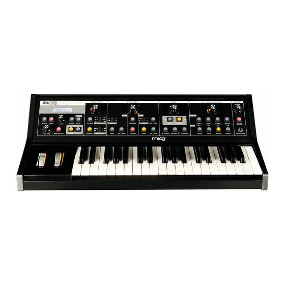
Page 5: Overview And Features
The Little Phatty (LP for short) is a monophonic analog synthesizer that is a descendant of the classic Minimoog Model D. The LP features 2 ultra-stable oscillators, a genuine Moog 24dB/Octave low pass filter, two 4-stage analog envelope generators and a flexible modulation matrix. The LP’s front panel has four variable-function edit controls for real time adjustment of the Modulation, Oscillator, Filter and Envelope Generator parameters, plus dedicated controls for Fine Tuning, Octave Switching, Glide, and Volume. - Page 6 LP Stage II User’s Manual - The Basics Front Panel (con’t): 6. The Output section - includes controls for adjusting the Master Volume, a switch to toggle the output on and off, and a headphone jack. The Master Volume is used for setting the levels of both the output and the headphones.
-
Page 7: Signal Flow
LP Stage II User’s Manual - The Basics Signal Flow To understand the operation of the Little Phatty, take a look at the diagram below. The diagram shows the flow of the audio, control voltage and modulation signals in the Little Phatty. Heavy lines are used to indicate audio signals, which flow from left to right. -
Page 8: Basic Operation
LP Stage II User’s Manual - The Basics Basic Operation The LP has two operating modes: Master and Preset. • Master mode allows you to access and change global parameters and other utility options. A complete list of the Master mode functions and parameters is shown on page 26. •... -
Page 9: The Components
The Components Now let’s take a look at the individual module components that make up the Little Phatty Synthesizer, start- ing with the Oscillator section and moving right across the front panel, explaining the features and functions of the Filter, Envelope Generator and Output sections. Then we’ll cover the Modulation section, the Key- board and Left-Hand controls, the Input/Output Side Panel, and the User Interface section. - Page 10 LP Stage II User’s Manual - The Components Waveform: Each oscillator has a switch labeled WAVE that allows the analog edit control to modify the waveform. The waveform is continuously variable from triangle, to sawtooth, to square, to rectangular. The waveform is morphed gradually from one to another as the value control is rotated.
-
Page 11: Filter Section
An 18dB/Octave slope is steeper still, with a corresponding frequency rejection. Finally, a 24dB/Octave slope provides the steepest rejection of frequencies above the cutoff point. The classic Moog filter is a 24dB/ Octave lowpass filter. The Moog filter also features a parameter called Resonance. This parameter adds a resonant peak at the cutoff frequency. - Page 12 LP Stage II User’s Manual - The Components Finally, the OVERLOAD parameter allows you to set the amount of signal clipping from none to soft to hard clipping as the amount is increased. The results you get with OVERLOAD will depend on the settings of the oscillator waves and levels, and the filter cutoff and the filter resonance settings in addition to Overload amount.
-
Page 13: Tech Notes
TECH NOTES: 1. The LP’s Overload circuit uses asymmetrical clipping, which clips each side of the waveform differently. Asymmetrical clipping circuits tend to produce tones with unique richness and character. 2. The Overload circuit has no effect on the sound when the analog edit control is set fully counter- clockwise. - Page 14 The KB GATE jack on the side panel is a trigger input that accepts a footswitch (momentary, normally closed like the Moog FS-1) or a gate signal. Pressing the footswitch or applying a gate signal (+5V) causes both envelopes (Volume and Filter) to trigger.
-
Page 15: Modulation Section
D. The Modulation Section Modulation is the heart of making interesting sounds with analog subtractive synthesis. The LP’s Modulation section opens up a world of modulation possibili- ties that were not available on the original Minimoog. The Modulation section allows you to select from six modulation sources, four destinations, and set the modulation amount. -
Page 16: Output Section
The VOLUME jack on the side panel is a CV input for external control of the Output a positive control voltage from 0 to 5 Volts, or an expression pedal like the Moog EP-2. A voltage of 0 volts silences the LP, and a voltage of 5 volts corresponds to the output level set by the VOLUME control knob. -
Page 17: Keyboard & Lh Controllers
F. Keyboard and Left-Hand Controllers Pitch Bend Wheel: This spring-loaded control affects the pitch of both oscillators. The amount of pitch bend can be set for each direction (UP/DOWN) independently via the Advanced Preset Menu (see page 35) and saved in each preset. -
Page 18: Input/Output Panel
Moogerfooger EP-2 (ring = +5.5 supply to the pedal, tip = variable CV return), or a control voltage from –5 to +5 Volts. The KB Gate Input accepts a footswitch (a momentary, normally-closed footswitch like the Moog FS-1) or a +5 Volt Gate Signal. MIDI Connectors (DIN and USB): These are connections for MIDI In/Out. -
Page 19: Interface Panel
H. Interface Panel The Interface Panel is located on a far left of the instrument. The Interface Panel provides a status display and controls for all of the Little Phatty’s software functions and instrument settings. Section Controls: Master: Pressing the MASTER switch places you in Master mode. In this mode, the VALUE knob is used to scroll through the Master mode menus for the Little Phatty. - Page 20 LP Stage II User’s Manual - The Components Fine Tune: The FINE TUNE control is used to tune the Little Phatty’s oscillators ±3 semitones for matching an external reference pitch. Glide On/Off: The GLIDE ON/OFF switch enables or disables the glissando effect between notes. Glide is ON when the switch LED is lit.
-
Page 21: Preset Mode
Preset Mode Preset mode is the default mode when the LP is powered on. Preset Mode is used to access presets and provide control for editing, naming and storing sounds. You can toggle between the stored and edited sound by pressing the PRESET button. This acts like a COMPARE function, allowing you to compare the sound of the original and edited presets. - Page 22 LP Stage II User’s Manual - The User Interface NOTE: When the Arpeggiator is running, the ENTER/STORE button is also used to activate the latch if the Latch parameter has been enabled. For more on the Arpeggiator and Latch functions, see page 39. Changing A Preset Name Changing a preset name is a simple operation.
- Page 23 Tap Tempo Tap Tempo is an easy and intuitive way to adjust the speed of the LFO Rate or the Arpeggiator Clock. The Tap Tempo function is always available for any preset in PRESET Mode. Tap Tempo can be used to adjust the LFO Rate when the Arpeggiator is not running,, or adjust the Arpeggiator Clock when the Arpeggiator is running.
-
Page 24: A. Menus
LP Stage II User’s Manual - The User Interface Master Mode Master Mode is used to access the global settings and Advanced Preset settings for the Little Phatty, and the routines for sending and receiving data. A. Master Mode Menus Descriptions of each individual Master Mode menu appears below. - Page 25 ADVANCED PRESET: LFO SYNC: Advanced Presets is a set of menus that allows you to access additional parameters for the selected preset. These parameters are stored individually for each preset. There are eleven Advanced Preset menus: - Filter Poles - EGR Release - Gate Trigger Options - Filter Sensitivity - Additional LFO Modulation Sources (SRC5 &...
-
Page 26: Analogue Mode
LP Stage II User’s Manual - The User Interface ANALOGUE MODE: KEYBOARD PRIORITY: Page 28 CLOCKS/QUARTER TIME VALUE NOTE 1/32 note Dotted 1/32 note 1/16 note Dotted 1/16 note Dotted 1/8 note Quarter note Dotted quarter note Half note Dotted half note Whole note Whole note + quarter note Whole note + half note... - Page 27 PROGRAM CHANGE SEND/RECEIVE: TUNING This menu item is used to enable or disable the transmission (SND) and reception (RCV) of MIDI program changes. To change the status of either parameter use the CURSOR button to highlight the param- eter, then use the VALUE knob to set the new parameter value. Values: ON, OFF;...
- Page 28 LP Stage II User’s Manual - The User Interface NOTE: While you are in this menu with AutoTune enabled, the output of the LP will be muted (the Output ON/OFF button status will not change, however). The reason for muting the output is that AutoTune uses a special Calibration Preset tone which isn’t very musical.
-
Page 29: Midi Setup
MIDI CHANNELS IN AND OUT: MIDI SETUP: TECH NOTE: ‘DIN’ is an abbreviation for ‘Deutsches Institut für Normung’ (German Institute for Standardization). ‘DIN connectors’ commonly refer to a family of circular connectors that were standardized by the DIN for commercial electronic use. When the MIDI standard was released in 1983, it specified a 5-pin DIN connector as the hardware interconnection, thus the ‘MIDI DIN’... - Page 30 LP Stage II User’s Manual - The User Interface MIDI SETUP (con’t) NOTE: When using MIDI Merge, take precautions to insure that you do not create a MIDI feedback loop (the output is passed back into the input and then merged with the output again), or you may experience unwanted side effects like a locked-up LP.
- Page 31 LP. Turn off LOCAL CONTROL on the first LP so that it is con- trolled only by the MIDI data that is shared between the two synths. If you have more than two Moog synths, connect them so that MIDI passes through each synth and the last is connected to the first; but make sure that the first synth does NOT pass MIDI through to the next, or you will create a MIDI feedback loop.
-
Page 32: Sysex Menu
LP Stage II User’s Manual - The User Interface SYSEX MENU: SYSTEM UTILITIES: PERFORMANCE TIP: You can quickly change a Master Menu parameter during performance by first entering Master Mode and select the desired parameter menu using the VALUE knob, then return to Preset Mode. -
Page 33: Filter Poles
B. Advanced Preset menus The Advanced Preset menu provides a set of additional programming parameters for each preset. These parameters are stored individually for each preset. FILTER POLES: EGR RELEASE: GATE: FILTER SENSITIVITY (FILT. SENS): LP Stage II User’s Manual - The User Interface This menu allows you choose the number of Filter Poles for the preset. - Page 34 LP Stage II User’s Manual - The User Interface MOD SOURCE 5 (MOD SRC 5): MOD SOURCE 6 (MOD SRC 6): MODULATION DESTINATION 2 (MOD DEST2): PITCH BEND (PB): Page 36 This menu allows you to select one of two modulation options that will be used when the FILT ENV source is selected on the front panel (Modulation Source 5).
- Page 35 KEYBOARD PRIORITY (KB PRIOR): POT MAPPING: NOTE: When Pot Mapping is enabled for a given panel section, the mapping assignment overrides the normal CC assignments in that section. For example, in the Modulation section, the LFO Rate is transmitted as CC#03, and the Amount transmitted as CC #06. If you set up Pot Mapping in the Modulation section to send MIDI CC#21, the Modulation knob will exclusively transmit CC#21 when Pot Mapping is enabled, and not CC#03 or #06.
- Page 36 LP Stage II User’s Manual - The User Interface POT MAPPING (con’t): PERFORMANCE TIP: Here’s a Pot Mapping example: suppose you have an external audio device that you want to control independently of the LP. You could program Pot Mapping to have the Modulation control transmit MIDI CC #XX, but only have it programmed for external control (EXT).
- Page 37 ARPEGGIATOR: The Arpeggiator is exciting addition to the LP’s operating system, provid- ing a wide range of musical sequencing possibilities. The Arpeggiator is programmed for each preset individually through the seven menu pages described here. The Arpeggiator is activated from the front panel (see Activating the Arpeggiator and Latch, page 52).
- Page 38 LP Stage II User’s Manual - The User Interface ARPEGGIATOR (Con’t): Page 40 The third page of the Arpeggiator menu allows you to specify the Arpeggiator Clock Divider. The available Arpeggiator Clock Divider values are the same as the LFO Clock Divider (see table on page 28). To make a selection, use the CURSOR button to move to the divider parameter field, then use the VALUE knob to select the desired divisor value.
-
Page 39: System Exclusive
ARPEGGIATOR (Con’t): C. SYSEX (System Exclusive) Menus SysEx menus are a set of commands to transmit and receive selected presets, bulk dumps and firmware dumps. To enable SysEx menus, press the CURSOR button. This will highlight the menu options shown on the second line of the display. -
Page 40: Send All Presets
LP Stage II User’s Manual - The User Interface C. SYSEX Menus (Con’t) SEND ALL PRESETS: BULK DUMP: Page 42 This option allows you to send the system exclusive data for archiving the complete bank of presets in the LP’s memory. To complete this command, enable the device that is to receive the SysEx data. -
Page 41: Firmware Updates
Receiving SysEx Data The LP is able to receive System Exclusive data at any time without any special prior setup. SysEx files are recognized and received automatically when a SysEx data transfer is initiated. The Little Phatty’s LCD screen will display the status of SysEx data transfers as follows: SINGLE PRESETS: ALL PRESETS: BULK DUMP:... -
Page 42: System Utilities
LP Stage II User’s Manual - The User Interface D. System Utilities Menus Page 44 System Utilities provide a set of useful system commands, including commands to calibrate, restore factory defaults and set global system options. There are seven pages of System Utilities menus, beginning with the Version number display. - Page 43 The sixth page of the System Utilities menu allows you to calibrate the Little Phatty. In the past, calibration of analog synthesizers had to be performed manually by experienced service personnel. The LP’s built- in calibration utilities now allow you to perform many of these proce- dures yourself, without the expense and hassle of shipping the LP back to the factory for calibration.
-
Page 44: Pitch Wheel
LP Stage II User’s Manual - The User Interface CALIBRATION (con’t) PITCH WHEEL: Note: If this calibration is done incorrectly, the Pitch Wheel will not operate normally and may not function at all. If this should this happen, try recalibrating the Pitch Wheel again using the procedure described. - Page 45 CALIBRATION (con’t) NOTE CALIBRATION: Note: A full Note calibration using the default range (12 - 116) can take about two hours to complete. By specifying a narrower range of notes (for example, just the range of the LP keyboard without octave transpose [48-84], or with octave transpose [24-108]), you can shorten the calibration time.
- Page 46 LP Stage II User’s Manual - The User Interface CALIBRATION (con’t) PITCH WHEEL AMOUNT: Page 48 This option allows you to select Pitch Wheel Amount calibration. This calibrates the Pitch Wheel Amount parameter to precise semitone values (± 2, 3, 4, 5, 7 and 12). Press ENTER to access the Pitch Wheel Amount calibration menu.
- Page 47 CALIBRATION (con’t) OSCILLATOR 2 FREQUENCY (OSC2 FREQ): This option allows you to select OSC2 Frequency Calibration. This calibrates the OSC2 FREQ control so that turning the editing dial all the way CCW turns OSC2 down exactly a fifth (-7 semitones) and turning all the way CW turns OSC2 up exactly a fifth (+7 semitones).
-
Page 48: Performance Sets
LP Stage II User’s Manual - The User Interface Performance Sets Performance Sets is a feature that allows you to customize the order of LP presets for a live performance situation or to enhance your productivity in a studio environment. Performance Sets are based on the idea that during a performance, you may need to switch between a se- quence of sounds that doesn’t necessarily match up to the preset locations. - Page 49 Editing Performance Sets To edit a Performance Set, use the CURSOR key to select the Performance SET number (1-4), ENTRY location (1-8) and PRESET (00-99). For example, to select the SET number, press the CURSOR button once to highlight the SET number for editing. Press the CURSOR button a second time to advance to the ENTRY location, and a third time to advance to the PRESET.
-
Page 50: Activating The Arpeggiator And Latch
LP Stage II User’s Manual - The User Interface Activating the Arpeggiator and Latch Turning the Arpeggiator ON/OFF When a preset has the Arpeggiator function enabled, you turn the Arpeggiator ON and OFF by pressing the VALUE encoder switch (you must be in PRESET mode to engage the Arpeggiator). When the Arpeggiator is ON, an ‘A’... - Page 51 Arpeggiator Examples The Arpeggiator takes the currently played note or group of notes and forms an arpeggio based on the Arpeggiator Menu settings. Here are some simple examples of the Arpeggiator function: Example 1. Pattern = UP, Octaves = 1, Mode = LOOP PLAY &...
-
Page 52: How The Lp Handles Midi
LP Stage II User’s Manual - The User Interface How the LP handles MIDI When you adjust any one of the LP’s four analog edit controls, MIDI Continuous Controller (CC) mes- sages are generated and transmitted on the MIDI Out connector. The information contained in these MIDI messages varies according to the parameter assignment for that analog edit control. - Page 53 SECTION CONTROL/PARAMETER MASTER PRESET CURSOR ENTER GLIDE ON/OFF OCTAVE UP OCTAVE DOWN LFO RATE AMOUNT SOURCE DESTINATION LFO SYNC SOURCE LFO SYNC CLOCK DIV MOD SOURCE 5 MOD SOURCE 6 MOD DEST 2 OSC 1 OCTAVE WAVE OSC 1 LEVEL GLIDE RATE 1-2 SYNC OCTAVE...
- Page 54 LP Stage II User’s Manual - The User Interface SECTION CONTROL/PARAMETER ATTACK DECAY SUSTAIN RELEASE ATTACK DECAY SUSTAIN RELEASE EGR RELEASE ON/OFF EGR LEGATO ARPEGGIATOR ENABLE ARP RUN/STOP ARP CLOCK RATE (SEE NOTE 2) ARP CLOCK SOURCE ARP CLOCK DIVISIONS ARP RANGE (OCTAVES) ARP PATTERN ARP MODE...
- Page 55 TIME VALUE 1/32 note Dotted 1/32 note 1/16 note Dotted 1/16 note 1/8 note Dotted 1/8 note Quarter note Dotted quarter note Half note Dotted half note Whole note Whole note + quarter note Whole note + half note Whole note + dotted half note Whole note + whole note MIDI CC values for the LFO and Arpeggiator Clock Divider (CC#103 &...
-
Page 56: Appendix A - Master Mode Menu Tree
LP Stage II User’s Manual - Appendices Appendix A - MASTER MODE Menu Tree The structure of the Master Mode menus is shown below. With the exception of the Advanced Preset parameters, which are individually stored with each preset, all Master Mode menu parameters effect the LP globally. -
Page 57: Appendix B - Lfo Sync Modes
Appendix B - LFO Sync Modes There are two LFO Sync Modes: INTERNAL and MIDI CLOCK. INTERNAL: When the LFO Sync Mode is set to ‘INTERNAL’, the LFO rate is controlled directly via the MODULATION knob (when the LFO RATE panel button is selected), or by Tap Tempo, or by sending a MIDI CC#3 com- mand with a value between 0-127 (MIDI CC#3 controls the LFO RATE). -
Page 58: Appendix C - Arpeggiator Clock Source
LP Stage II User’s Manual - Appendices Appendix C - Arpeggiator Clock Source There are three Arpeggiator Clock Sources: Internal (INT), LFO, and MIDI Clock (MIDI). Detailed descriptions of these clock source options appears below. INTERNAL: When the Arpeggiator Clock Source is set to INTERNAL, the Arpeggiator runs at the internal Arpeggiator Clock rate. -
Page 59: Appendix D - The Calibration Preset
Appendix D - The Calibration Preset The LP has a specific Calibration Preset that is stored in a non-volatile memory location labeled ‘CA’ (this preset location appears after preset 99). The Calibration Preset is a single-oscillator squarewave tone that plays Oscillator 1 at full level. This preset is used primarily for the LP’S AutoTune function, but it can also be used for tuning the LP with an external tuner. -
Page 60: Appendix E - Accessories
LP Stage II User’s Manual - Appendices Appendix E - Accessories To further enhance the functionality of the Little Phatty, Moog Music offers the following optional accessories. For complete information on everything listed here, including pricing and ordering info, see your Moog dealer, or visit www. -
Page 61: Appendix F - Tutorial
Appendix F - Tutorial For those who are new to the world of electronic music, let’s take a few moments to go through the basics of sound and synthesis. A third perception of sound is its tone color, also known as its timbre. There is no standard of measurement for timbre, so instead we use familiar terms to describe the tone color of a sound –... - Page 62 LP Stage II User’s Manual - Appendices The Oscillator is the starting point of Subtractive Synthesis, for it is here that the initial sound is created. The oscillator creates electrical vibrations which function in a manner similar to the strings of a guitar; they create the signal source that the rest of the system will use to modify and shape the sound.
- Page 63 Synthesizers often have more than one oscillator, and each oscillator usually has its own frequency and waveform and level (volume) parameters. Several oscillators make possible rich and complex sound source configurations. Some synthesizers also permit external audio signals to serve as sound sources, allowing you to combine them with the oscillators, or process the external audio by itself using the synthesizer compo- nents.
- Page 64 LP Stage II User’s Manual - Appendices Returning to our Subtractive Synthesis model, the first of the auxiliary components is the keyboard. The keyboard provides a familiar musical instrument ‘interface’ that produces a control voltage and trigger signal whenever a key is pressed. The level of the control voltage signal is a function of which key is pressed - the higher up on the keyboard you play, the higher the level of the control voltage.
- Page 65 This is especially true of the oscillators and envelope generators (the Little Phatty has two of each), but may also be true of filters, amplifiers and LFO’s. For example, the Moog Voyager has three oscilla- tors, two filters, two amplifiers, an LFO, two extensive modulation sections, and the Voyager’s third oscillator can act as an additional LFO.
-
Page 66: Appendix G - Midi Implementation Chart
LP Stage II User’s Manual - Appendices Appendix G - MIDI Implementation Chart Moog Music Little Phatty Stage II Analog Synthesizer FUNCTION Basic channel Default Changed Mode Default Messages Altered Note number Velocity Note ON Note OFF After touch Pitch Bend... -
Page 67: Appendix H - Service And Support Information
Music before returning any product. You can request an RMA number on-line using the ‘Product Register’ link on the Moog Music home page or call us at (828) 251-0090. The Little Phatty must be returned in the original inner packing including the foam inserts. The warranty will not be honored if the product is not properly packed. -
Page 68: Appendix J - Using The Cp-251 With The Little Phatty
Attenuators to have two separately controllable modulation sources for the LP. Pitch Transposition: Using an Expression Pedal (like the Moog EP-2), you can program the CP-251 to transpose the LP’s pitch to any interval desired and have it ready any time you need it. Here’s the connection: - Connect the EP-2 to an Attenuator Input. - Page 69 To set the transposition interval, press the EP-2 footpedal all the way down and slowly adjust the Attenuator on the CP-251 while striking a note on the LP. The pitch will go up as you raise the Attenuator level. Rock the EP-2 pedal between full up and full down positions to hear the difference in pitch, and adjust the Attenuator until the desired interval is reached.
-
Page 70: Appendix K - Specifications
LP Stage II User’s Manual - Appendices Appendix K - Specifications Type: Programmable monophonic analog synthesizer w/100 presets Synth Engine: Oscillator Section: Oscillator 1: Octave: 16’, 8’, 4’, 2’ Wave: Continuously variable (triangle/sawtooth/square/pulse) Level: 0 to 100% Oscillator 2: Frequency: ± 7 semitones Octave: 16’, 8’, 4’, 2’... -
Page 71: Glossary
Glossary Here are a few key terms that cover the basics of sound generation as used in the Little Phatty synthesizer. ADSR – Abbreviation for Attack, Decay, Sustain and Release, the four stages of an envelope control Amplitude – The strength of a sound’s vibration measured in Decibels (dB). Amplitude corresponds to the musical term Loudness. - Page 72 Their waveforms look chaotic. White noise is an enharmonic sound that contains equal amounts of all frequencies. Little Phatty – A monophonic analog synthesizer designed by Bob Moog that is a descendant of the classic Minimoog.
- Page 73 Low Frequency Oscillator – Also called an LFO, this is a special type of oscillator that generates signals primarily below the range of human hearing (generally below 20 Hz). LFOs are typically used as a source of modulation. For instance, an LFO with a triangle waveform, set to about 6 Hz and modulating the pitch of a VCO results in vibrato.
- Page 74 LP Stage II User’s Manual - Glossary Sound – Audible vibrations of air pressure. For electronic sounds such as those produced by a synthesizer, loudspeakers are used translate the electrical vibrations into the changes in air pressure which we perceive as sound.
-
Page 75: Stage Ii Presets
Stage II Preset Contributors: Text and illustrations by Greg Kist, Cyril Lance & Amos Gaynes Steve Dunnington Amos Gaynes Adam Holzman Jordan Rudess Huston Singletary Little Phatty Stage II User’s Manual © Moog Music 2009, all rights reserved Page 77... - Page 76 Page 78...
Need help?
Do you have a question about the Little Phatty Stage II Edition and is the answer not in the manual?
Questions and answers