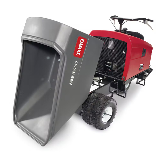
Toro MB-1600 Operator's Manual
Mud buggy
Hide thumbs
Also See for MB-1600:
- Operator's manual (36 pages) ,
- Operator's manual (57 pages) ,
- Operator's manual (36 pages)

Related Manuals for Toro MB-1600


Summary of Contents for Toro MB-1600
- Page 1 Form No. 3385-259 Rev A MB-1600 Mud Buggy Model No. 68038—Serial No. 313000001 and Up Model No. 68038G—Serial No. 313000001 and Up g019616 www.discount-equipment.com *3385-259* A Original Instructions (EN)
- Page 2 We sell worldwide for the brands: Genie, Terex, JLG, MultiQuip, Mikasa, Essick, Whiteman, Mayco, Toro Stone, Diamond Products, Generac Magnum, Airman, Haulotte, Barreto, Power Blanket, Nifty Lift, Atlas Copco, Chicago Pneumatic, Allmand, Miller Curber, Skyjack,...
-
Page 3: Introduction
Whenever you need service, genuine Toro parts, or additional WARNING information, contact an Authorized Service Dealer or Toro Customer Service and have the model and serial numbers of your product ready. Figure 1 identifies the location of the CALIFORNIA model and serial numbers on the product. Write the numbers Proposition 65 Warning in the space provided. -
Page 4: Table Of Contents
Contents Safety Improper use or maintenance of the machine can result Introduction ..............2 in injury. To reduce the potential for injury, comply with Safety ................3 these safety instructions and always pay attention to the Safe Operating Practices........... 3 safety alert symbol , which means: Caution , Warning , Safety and Instructional Decals ......... - Page 5 • – Keep container nozzle in contact with the tank during Never jerk the controls; use a steady motion. filling. • Watch for traffic when operating near or crossing • Ensure that the machine’s shields are attached and roadways. functioning properly. Do not operate unless they are •...
- Page 6 Keep the machine free of grass, leaves, or other debris build-up. Clean up oil or fuel spillage. • Use only genuine Toro replacement parts to ensure that original standards are maintained. • Keep your body and hands away from pin hole leaks or nozzles that eject high pressure hydraulic fluid.
-
Page 7: Safety And Instructional Decals
Safety and Instructional Decals Safety decals and instructions are easily visible to the operator and are located near any area of potential danger. Replace any decal that is damaged or lost. 125-4961 125-4960 125–4961 125–4960 1. Reverse 1. Forward 125–4964 1. - Page 8 125–6694 125–4967 1. Tie down location 1. Lift point 127–2855 1. Warning—read the Operator’s Manual; wear hearing 5. Tipping hazard—do not raise the dump trailer while moving; protection. move forward slowly; raise the dump trailer slowly. 2. Warning—do not operate the machine without proper training. 6. Choking hazard—do not run the engine indoors. 3.
- Page 9 130-2844 1. Raise the pedal to lower 2. Lower the pedal to raise 125–8190 the hopper. the hopper. 1. Press down on the pedal 2. Release the pedal to to apply the service brake release the service brake 117–2718 125–4963 1.
-
Page 10: Product Overview
Product Overview g019617 Figure 3 1. Operator platform 4. Drive tires 7. Dump handle/pedal 10. Brake pedal 2. Steer tires 5. Handle bars 8. Fuel tank 3. Reverse-speed-control 6. Forward-speed-control 9. Parking brake lever lever Controls Fuel Gauge Become familiar with all the controls (Figure 3) before you The fuel gauge is part of the fuel-tank cap, and the gauge start the engine and operate the machine. -
Page 11: Specifications
Engine Controls Fuel-shutoff Valve The fuel-shut off valve (Figure 5) is located underneath the Oil Alert System choke lever. Move the shutoff valve must to the On position before attempting to start the engine. Once you have finished The oil alert system is designed to prevent engine damage using the machine and you have turned the engine off, move caused by an insufficient amount of oil in the crankcase. -
Page 12: Operation
Operation DANGER In certain conditions during fueling, static Note: Determine the left and right sides of the machine electricity can be released causing a spark which from the normal operating position. can ignite the gasoline vapors. A fire or explosion from gasoline can burn you and others and can Important: Before operating, check the fuel and oil damage property. -
Page 13: Checking The Engine Oil Level
Note: A fuel stabilizer/conditioner is most effective when mixed with fresh gasoline. To minimize the chance of varnish deposits in the fuel system, use fuel stabilizer at all times. Filling the Fuel Tank Fuel tank capacity: 21.6 liters (5.7 US gallons). 1. -
Page 14: Checking The Hydraulic Fluid Level
Checking the Hydraulic Fluid CAUTION Level The hydraulic breather/filler cap is designed to pressurize the reservoir to 34 kPa (5 psi). Service Interval: Before each use or daily Loosen the cap slowly to avoid injury whenever Hydraulic fluid type: Mobil 424 Hydraulic Oil or equivalent adding oil or working on the hydraulic system. -
Page 15: Operating The Machine
Authorized Toro Distributor. be damaged. 7. Use your foot to press the brake pedal; refer to Brake 9. -
Page 16: Parking The Machine
Parking the Machine Transporting the Machine When transporting the machine on a trailer, always use the Parking on a Grade following procedure: Important: Do not operate or drive the machine on Parking the machine on a grade should be avoided if possible. If the machine must be parked on a grade, park it at a right roadways. - Page 17 Lift the machine with a fork lift from the side or from the front (Figure 13 and Figure 14). Pull out on the platform release ring (Figure 15) and raise the standing platform to allow access to the fork pockets. g019610 Figure 13 1.
-
Page 18: Using The Quick-Release Tire Hubs
Using the Quick-release Tire Hubs The quick-release tire system allows quick removal of the outer machine tires. The quick-release system allows the machine to be converted from a 117 cm (46 inch) to a 91 cm (36 inch) wide machine without any special tools for hub removal. -
Page 19: Maintenance
Maintenance Note: Determine the left and right sides of the machine from the normal operating position. Recommended Maintenance Schedule(s) Maintenance Service Maintenance Procedure Interval • Change the engine oil. After the first 50 hours • Check the engine oil level. •... -
Page 20: Premaintenance Procedures
Premaintenance Procedures Removing the Cowl Note: You must dump the hopper before you remove the cowl. This can be done by either using the hydraulics, or by removing the pin in the hydraulic cylinder and the hopper base. 1. Before removing the cowl (Figure 17), stop the engine and allow the engine to cool. -
Page 21: Lubrication
Lubrication Engine Maintenance Servicing the Air Cleaner Greasing the Machine Service Interval: Every 50 hours—Clean the air cleaner. Service Interval: Every 50 hours—Grease and oil the Every 300 hours—Replace the paper element. machine. 1. Make sure that the wire is off the spark plug. Yearly—Pack wheel bearings. -
Page 22: Changing The Engine Oil
Changing the Engine Oil 6. Cleaning the foam element: A. Wash foam element in a solution of liquid soap Service Interval: After the first 50 hours—Change the and warm water. engine oil. Note: Squeeze to remove dirt, but do not twist Every 100 hours—Change the engine oil. -
Page 23: Replacing The Spark Plug
Replacing the Spark Plug Fuel System Maintenance Service Interval: Every 100 hours—Check/adjust the spark plug. Every 300 hours—Replace the spark plug. Cleaning the Sediment Cup Spark plug type: NGK BPR 6ES spark plug or equivalent. Service Interval: Every 100 hours—Clean the sediment cup. Air gap: 0.70-0.80 mm (0.028-0.031 inch). -
Page 24: Changing The Fuel Filter
4. Rotate the lever for the engine switch clockwise to the Stop position, and allow the engine to cool (Figure 25). 5. Carefully remove the spark-plug wire from the terminal of the spark plug (Figure 26). G018789 G020544 Figure 24 1. -
Page 25: Draining The Fuel Tank
Drive System 10. Align the clamps over the hoses at the barbed area of the filter, and secure the clamps to the hoses. Maintenance 11. Connect the spark-plug wire (Figure 26). 12. Open the tank-shutoff valve and turn on the engine switch, and check for fuel leaks (Figure 25). -
Page 26: Checking The Tires And Lug Nuts
Authorized Toro Service Dealer for repair. Checking the Service Brake Service Interval: Before each use or daily 1. - Page 27 The engine should stall at full engagement of speed control. 9. Release the speed-control lever. 10. If the machine moves forward or backward, have the machine repaired at an Authorized Toro Service Dealer. Figure 31 1. Parking brake knob Checking the Parking Brake Service Interval: Before each use or daily 5.
-
Page 28: Hydraulic System Maintenance
Hydraulic System Note: Rotate the knob no more than 1 revolution each time. Maintenance 5. Test the parking brake; refer to Checking the Parking Brake (page 26). WARNING 6. Repeat steps 1 through 5 until the machine does not move forward. Hydraulic fluid escaping under pressure can penetrate skin and cause injury. -
Page 29: Changing The Hydraulic Fluid
6. Install the replacement hydraulic filter onto the filter 5. Place a large drain pan under the drain plug located at adapter (Figure 32). Tighten it clockwise until the the bottom of the hydraulic tank. rubber gasket contacts the filter adapter, then tighten 6. -
Page 30: Cleaning
Cleaning Storage 1. Stop the engine and set the parking brake. Removing Debris from the 2. Remove dirt and grime from the external parts of the Machine entire machine, especially the engine. Clean dirt and chaff from the outside of the engine cylinder head fins and blower housing. - Page 31 We sell worldwide for the brands: Genie, Terex, JLG, MultiQuip, Mikasa, Essick, Whiteman, Mayco, Toro Stone, Diamond Products, Generac Magnum, Airman, Haulotte, Barreto, Power Blanket, Nifty Lift, Atlas Copco, Chicago Pneumatic, Allmand, Miller Curber, Skyjack,...
- Page 32 Select an option below to find your Equipment We sell worldwide for the brands: Genie, Terex, JLG, MultiQuip, Mikasa, Essick, Whiteman, Mayco, Toro Stone, Diamond Products, Generac Magnum, Airman, Haulotte, Barreto, Power Blanket, Nifty Lift, Atlas Copco, Chicago Pneumatic, Allmand, Miller Curber, Skyjack, Lull,...