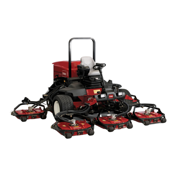
Toro Groundsmaster 4500-D Operator's Manual
Traction unit
Hide thumbs
Also See for Groundsmaster 4500-D:
- Service manual (474 pages) ,
- Operator's manual (92 pages) ,
- Installation instructions manual (28 pages)
Table of Contents

Related Manuals for Toro Groundsmaster 4500-D


Summary of Contents for Toro Groundsmaster 4500-D
- Page 1 Form No. 3416-993 Rev A Groundsmaster ® 4500-D and 4700-D Traction Unit Model No. 30873—Serial No. 401110001 and Up Model No. 30874—Serial No. 401410001 and Up *3416-993* A Register at www.Toro.com. Original Instructions (EN)
- Page 2 Whenever you need service, genuine Toro parts, or additional information, contact an Authorized Service Dealer or Toro Customer Service and have the model and serial numbers of your product ready. Figure 1 identifies the location of the model and serial numbers on the right front frame of the product.
-
Page 3: Table Of Contents
Contents Service Interval Chart ........40 Pre-Maintenance Procedures ......41 Pre-Maintenance Safety ........41 Safety ............... 4 Preparing the Machine for Maintenance.... 41 General Safety ........... 4 Lifting the Machine ........... 41 Engine Emission Certification ......4 Opening the Hood ..........42 Safety and Instructional Decals ...... -
Page 4: Safety
Safety Installing the Cutting Units ........ 63 Servicing the Front Roller ......... 63 Blade Maintenance ..........64 This machine has been designed in accordance with Blade Safety ............. 64 EN ISO 5395:2013 and ANSI B71.4-2012. Servicing the Blade Plane......... 64 Removing and Installing the Cutting-Unit Blade(s) ............ -
Page 5: Safety And Instructional Decals
Safety and Instructional Decals Safety decals and instructions are easily visible to the operator and are located near any area of potential danger. Replace any decal that is damaged or missing. decal93-7818 93-7818 decal107-1971 1. Warning—read the Operator's Manual for instructions on 107–1971 torquing the blade bolt/nut to 115 to 149 N∙m (85 to 110 ft-lb). - Page 6 decalbatterysymbols Battery Symbols Some or all of these symbols are on your battery. 1. Explosion hazard 6. Keep bystanders a safe distance away from the battery. decal117-4764 117-4764 2. No fire, open flame, or 7. Wear eye protection; explosive gases can smoking 1.
- Page 7 decal121-3887 121-3887 1. Read the Operator’s Manual. decal120-8947 120-8947 1. Warning—read the 4. If the roll bar is raised, decal136-2931 Operator’s Manual. wear the seat belt. 136-2931 2. There is no rollover 5. If the roll bar is lowered, For Groundsmaster 4500 Only protection when the roll do not wear the seat belt.
- Page 8 decal125-4605 125-4605 1. Power seat (10 A) 6. Power supplied (10 A) decal125-4606 2. Work light (10 A) 7. GM4700 controller (2 A) 125-4606 3. Engine (10 A) 8. Power supplied (7.5 A) 1. Read the Operator’s Manual for information on 4.
- Page 9 decal127-6447 127-6447 (Affix over Part No. 112-5297 for CE* for 4500 series machines) Note: This machine complies with the industry standard stability test in the static lateral and longitudinal tests with the maximum recommended slope indicated on the decal. Review the instructions for operating the machine on slopes in the Operator's Manual and the conditions in which the machine is being operated to determine whether the machine can be operated in the conditions on that day and at that site.
- Page 10 decal127-6448 127-6448 (Affix over Part No. 112-5297 for CE* for 4700 series machines) Note: This machine complies with the industry standard stability test in the static lateral and longitudinal tests with the maximum recommended slope indicated on the decal. Review the instructions for operating the machine on slopes in the Operator's Manual and the conditions in which the machine is being operated to determine whether the machine can be operated in the conditions on that day and at that site.
-
Page 11: Setup
Setup Loose Parts Use the chart below to verify that all parts have been shipped. Procedure Description Qty. Replace the warning decal (CE Warning decal machines only). Hood-latch bracket Rivet Washer Install the hood latch. Screw (1/4 x 2 inches) Locknut (1/4 inch) –... -
Page 12: Installing The Hood Latch
Installing the Hood Latch Parts needed for this procedure: Hood-latch bracket Rivet Washer g012629 Figure 4 Screw (1/4 x 2 inches) 1. CE lock bracket 2. Bolt and nut Locknut (1/4 inch) Inside of the hood, align the washers with the Procedure holes in the hood. -
Page 13: Adjusting The Roller Scraper (Optional)
Installing the Mulching Baffle (Optional) No Parts Required g012631 Figure 6 Procedure 1. Bolt 3. Arm of hood-latch bracket Thoroughly clean debris from the mounting holes 2. Nut on the rear wall and left wall of the chamber. Install the mulching baffle in the rear opening and secure it with 5 flange-head bolts (Figure Adjusting the Roller... -
Page 14: Preparing The Machine
Preparing the Machine No Parts Required Procedure Park the machine on a level surface. Lower the cutting units. Engage the parking brake. Shut off the engine and remove the key. Check the tire pressure before use; refer to Checking the Tire Pressure (page 26). -
Page 15: Product Overview
Product Overview down on the right brake pedal while engaging the toe pedal. To release the parking brake, press 1 of the brake pedals until the parking brake latch retracts. Controls Tilt-Steering Pedal Press the tilt-steering pedal to tilt the steering wheel to the desired position, then release the pedal to lock the adjustment (Figure... - Page 16 High-Low Speed Control The switch (Figure 10) allows the speed range to increase for transporting the machine. To switch between the High and Low speed ranges, raise the cutting units, disengage the PTO and the cruise control, put the traction pedal into the N EUTRAL position, and move the machine at a slow speed.
- Page 17 Using the InfoCenter LCD Display Armrest Adjustment Knob Rotate the knob to adjust the armrest angle (Figure The InfoCenter LCD display shows information about 12). your machine, such as the operating status, various diagnostics and other information about the machine (Figure 13).
- Page 18 InfoCenter Icon Description InfoCenter Icon Description (cont'd.) SERVICE DUE Indicates when scheduled service should be performed The cruise control is on. Hours remaining until service Reset the service hours Shut off the engine The status of the engine rpm Engine Info icon Key switch Maximum traction speed setting...
- Page 19 Diagnostics Menu Item Description Left Cutting Unit Refer to the Service Manual or your authorized Toro Center Cutting Unit distributor for more information on the Engine Run menu and Right Cutting Unit the information contained Traction there.
- Page 20 Protected Menus Settings Menu Item Description There are 5 operating configuration settings that are adjustable within the Settings Menu of the InfoCenter: Units Controls the units used on the auto idle, maximum mowing ground speed, maximum InfoCenter (English or Metric) transport ground speed, Smart Power, cutting unit Language Controls the language used...
- Page 21 Setting the Maximum Allowed Mow Speed In the Settings Menu, scroll down to Mow Speed and press the right button. Use the right button to increase the maximum mow speed in 5% increments between 50% and 100%. Use the center button to decrease the maximum mow speed in 5% increments between 50% and 100%.
-
Page 22: Specifications
Specifications g198614 Figure 14... -
Page 23: Machine Specifications
88 kg (195 lb) Attachments/Accessories A selection of Toro approved attachments and accessories is available for use with the machine to enhance and expand its capabilities. Contact your Authorized Service Dealer or Distributor or go to www.Toro.com for a list of all approved attachments and accessories. -
Page 24: Before Operation
Checking the Engine-Oil Operation Level Note: Determine the left and right sides of the Before you start the engine and use the machine, machine from the normal operating position. check the oil level in the engine crankcase; refer to Checking the Engine-Oil Level (page 45). - Page 25 Petroleum Diesel Adding Fuel Use only clean, fresh diesel fuel or biodiesel fuels with low (<500 ppm) or ultra-low (<15 ppm) sulfur content. The minimum cetane rating should be 40. Purchase fuel in quantities that can be used within 180 days to ensure fuel freshness.
-
Page 26: Checking The Tire Pressure
Checking the Tire Pressure Service Interval: Before each use or daily The correct air pressure in the tires is 138 kPa (20 psi). Important: Maintain the recommended pressure in all tires to ensure a good quality of cut and proper machine performance. Do not under-inflate g033359 the tires. -
Page 27: Adjusting The Height Of Cut
Lowering the Roll Bar Adjusting the Height of Cut Important: Lower the roll bar only when Important: The cutting units often cut necessary. approximately 6 mm (1/4 inch) lower than a reel cutting unit with the same bench setting. It Important: Ensure that the seat is secured with may be necessary to set the cutting-unit bench... -
Page 28: Checking The Interlock Switches
If this time is greater than 7 seconds, CAUTION adjust the braking valve. Call your authorized Toro If safety interlock switches are disconnected distributor for assistance in making this adjustment. - Page 29 High-Lift, Parallel Sail The blade generally performs better in the higher heights of cut—7 to 10 cm (2 to 4 inches). Attributes: • It has more lift and a higher discharge velocity. • Sparse or limp turf is picked up significantly at higher heights of cut.
-
Page 30: Choosing Accessories
Choosing Accessories Angle Sail Blade High-Lift, Parallel-Sail Mulching Baffle Roller Scraper Blade (Do not use with the mulching baffle) Recommended in most May work well in light or Has been shown to Grass Cutting—1.9 to Can be used whenever 4.4 cm (3/4 to 1-3/4 applications sparse turf improve dispersion and... -
Page 31: Starting The Engine
Avoid operating the machine on wet grass. Tires • Use accessories and attachments approved by may lose traction; regardless if the brakes are The Toro® Company only. available and functioning. • Avoid starting, stopping, or turning the machine Rollover Protection System on a slope. -
Page 32: Shutting Off The Engine
Important: Do not run the starter motor accidentally. The brakes can also help you to maintain more than 15 seconds at a time or premature traction. For example, on some slopes, the uphill starter failure may result. If the engine fails wheel can slip and lose traction. -
Page 33: Using Cruise Control
Using Cruise Control The cruise-control switch locks in the pedal position to maintain the desired ground speed. Pressing the rear of the switch turns the cruise control off, the middle position of the switch enables the cruise-control function, and the front of the switch sets the desired ground speed. -
Page 34: Operating Tips
Operating Tips Resolving After-Cut Appearance Refer to the After-cut Appearance Troubleshooting Operating the Machine Guide available at www.Toro.com. • Start the engine. If the A function is Using Proper Mowing Techniques turned off, run it at H until it warms up. -
Page 35: After Operation
Checking the Condition of the After Operation Cutting-Unit Deck After Operation Safety Ensure that the cutting chambers are in good condition. Straighten any bends in the chamber • Clean grass and debris from the cutting units, components to ensure correct blade tip/chamber mufflers, and engine compartment to help prevent clearance. -
Page 36: Hauling The Machine
Securing the Cutting Units With the cutting units lowered, slip the loop of the lanyard into the slot in the reinforcement Ensure that the PTO is disengaged. plate of the roller support (Figure 27). Park the machine on a level surface. Engage the parking brake. -
Page 37: Locating The Tie-Down Points
Locating the Tie-Down Points Note: Use properly-rated DOT-approved straps in 4 corners to tie down the machine. • On each side of the frame by the operator’s platform • On the rear bumper g036666 g225685 g036664 Figure 28 Figure 29 1. -
Page 38: Maintenance
Important: Refer to your engine owner’s manual for additional maintenance procedures. Note: Download a free copy of the electrical or hydraulic schematic by visiting www.Toro.com and searching for your machine from the Manuals link on the home page. Note: Determine the left and right sides of the machine from the normal operating position. -
Page 39: Daily Maintenance Checklist
Maintenance Service Maintenance Procedure Interval • Drain and clean the fuel tank. • Check the tire pressure. • Check all fasteners. Before storage • Grease or oil all grease fittings and pivot points. • Paint chipped surfaces. • Inspect the fuel lines and connections. Yearly Daily Maintenance Checklist Duplicate this page for routine use. -
Page 40: Service Interval Chart
Notation for Areas of Concern Inspection performed by: Item Date Information Service Interval Chart decal125-4606 Figure 31... -
Page 41: Pre-Maintenance Procedures
Pre-Maintenance Lifting the Machine Procedures Use the following as points to lift the machine: Front of the machine—at the frame of the machine, forward of the wheel-drive motors (Figure Pre-Maintenance Safety Important: Do not support the machine at the • wheel-drive motors. -
Page 42: Opening The Hood
Opening the Hood Accessing the Hydraulic Lift Compartment Tilt the hood to access the chassis as shown in Figure Tilt the seat to access the hydraulic lift compartment as shown in Figure g036674 g036706 Figure 34 Figure 35... -
Page 43: Lubrication
Lubrication • Steering-cylinder ball joints (2) as shown in Figure Greasing the Bearings and Bushings Service Interval: Every 50 hours (also after every washing). Grease specification: No. 2 lithium grease The grease fitting locations and quantities are as follows: • Brake-shaft pivot bearings (5) as shown in Figure g009706... -
Page 44: Engine Maintenance
Engine Maintenance • Cutting-unit spindle-shaft bearings (2 per cutting unit) as shown in Figure 40 Note: You can use either fitting, whichever is Engine Safety more accessible. Pump grease into the fitting until a small amount appears at the bottom of the Shut off the engine before checking the oil or adding spindle housing (under the cutting unit). -
Page 45: Servicing The Engine Oil
– Preferred oil: SAE 15W-40 (above -18°C [0°F]) – Alternate oil: SAE 10W-30 or 5W-30 (all temperatures) Note: Toro Premium Engine oil is available from your authorized Toro distributor in either 15W-40 or 10W-30 viscosity. See the Parts Catalog for part numbers. Checking the Engine-Oil Level... - Page 46 Changing the Engine Oil and Filter Important: Keep the engine oil level between the upper and lower limits on the dipstick; the engine Service Interval: After the first 50 hours may fail if you run it with too much or too little oil. Every 250 hours Park the machine on a level surface.
-
Page 47: Fuel System Maintenance
Servicing the Fuel-Water Fuel System Separator Maintenance DANGER Under certain conditions, diesel fuel and fuel vapors are highly flammable and explosive. A fire or explosion from fuel can burn you and others and can cause property damage. • Use a funnel to fill the fuel tank outdoors, in an open area, when the engine is off and g198661 is cold. -
Page 48: Servicing The Fuel Filter
Replacing the Fuel-Filter Canister Servicing the Fuel Filter Service Interval: Every 400 hours—Replace the Service Interval: Every 400 hours fuel-filter canister. Clean the area around the fuel-filter head Replace the fuel-filter canister as shown in Figure (Figure 50). g028799 Figure 50 1. -
Page 49: Cleaning The Fuel-Pickup Tube Screen
Cleaning the Fuel-Pickup Priming the Fuel System Tube Screen Prime the fuel system before starting the engine for the first time, after running out of fuel, or after fuel The fuel-pickup tube, located inside the fuel tank, is system maintenance (e.g., draining the filter/water equipped with a screen to help prevent debris from separator, replacing a fuel hose). -
Page 50: Electrical System Maintenance
Coat the battery posts and cable connectors with your hands. Grafo 112X (skin-over) grease (Toro Part No. 505-47) • Fill the battery where clean water is or petroleum jelly to prevent corrosion. always available for flushing the skin. -
Page 51: Locating The Fuses
WARNING WARNING Incorrect battery cable routing could Charging the battery produces gasses damage the machine and cables, causing that can explode. sparks. Sparks can cause the battery Never smoke near the battery and keep gasses to explode, resulting in personal sparks and flames away from battery. -
Page 52: Drive System Maintenance
Drive System Maintenance g225611 Figure 57 g009985 Figure 55 Checking for End-Play in 1. Latch 2. Right storage box the Planetary Drives Replace the open fuse(s) as needed (Figure 56). Service Interval: Every 400 hours There should be no end-play in the planetary drives/drive wheels (i.e., the wheels should not move when you pull or push them in a direction parallel to the axle). -
Page 53: Checking The Planetary Gear-Drive Lubricant
Repeat step for the other drive wheel. If either wheel moves, contact your authorized g225606 Figure 60 Toro distributor to have the planetary drive rebuilt. 1. Check-plug hole 2. Check plug Checking the Planetary If the oil level is low, remove the fill plug at the 12 o’clock position and add oil until it begins to... - Page 54 Filling the Planetary-Gear-Drive with Lubricant Through the fill-plug hole, slowly fill the planetary with 0.65 L (22 fl oz) of high quality SAE 85W-140 wt gear lube. Important: If the planetary fills before the 0.65 L (22 fl oz) of oil is added, wait 1 hour or install the plug and move the machine approximately ten feet to distribute the oil through the brake system.
-
Page 55: Checking The Rear Axle And Gearbox For Leaks
Checking the Rear Axle and Gearbox for Leaks Service Interval: Before each use or daily Visually inspect the rear axle and rear-axle gearbox for leaks. g009716 Figure 66 1. Check plug 2. Fill plug Changing the Rear-Axle Lubricant Service Interval: After the first 200 hours Every 800 hours Lubricant specification: high-quality SAE 85W-140 gear lubricant... -
Page 56: Checking The Rear-Axle-Gearbox Lubricant
Checking the Rear-Axle-Gearbox Lubricant Service Interval: Every 400 hours The gear box is filled with SAE 85W-140 gear lube. The capacity is 0.5 L (16 fl oz). Visually inspect for leaks daily. g009169 Position the machine on a level surface. Figure 69 Remove the check/fill plug from the left side of 1. -
Page 57: Cooling System Maintenance
Cooling System Maintenance Cooling System Safety • Swallowing engine coolant can cause poisoning; keep out of reach from children and pets. • Discharge of hot, pressurized coolant or touching a hot radiator and surrounding parts can cause severe burns. – Always allow the engine to cool at least 15 minutes before removing the radiator cap. -
Page 58: Cleaning The Cooling System
Cleaning the Cooling System Service Interval: Before each use or daily—Remove debris from the engine area, oil cooler, and radiator. Clean them more frequently in dirty conditions. This machine is equipped with a hydraulically driven fan drive system that automatically (or manually) reverses to reduce oil cooler/radiator and screen debris buildup. -
Page 59: Brake Maintenance
Brake Maintenance Belt Maintenance Adjusting the Service Servicing the Alternator Brakes Belt Adjust the service brakes when there is more than Service Interval: Every 100 hours 25 mm (1 inch) of free travel of the brake pedal, or Proper tension of the belt allows 10 mm (3/8 inch) of when the brakes do not work effectively. -
Page 60: Hydraulic System Maintenance
Checking the This fluid is compatible with the elastomers used Hydraulic-Fluid Level in Toro hydraulic systems and is suitable for a wide-range of temperature conditions. This fluid is compatible with conventional mineral oils, but for Service Interval: Before each use or daily... -
Page 61: Changing The Hydraulic Fluid
Changing the Hydraulic Fluid Service Interval: Every 800 hours If the fluid becomes contaminated, contact your authorized Toro distributor, because the system must g198718 be flushed. Contaminated fluid looks milky or black when compared to clean oil. Park the machine on a level surface, engage the parking brake, lower the cutting units, shut off the engine, and remove the key. -
Page 62: Replacing The Hydraulic Filters
Replacing the Hydraulic Filters Service Interval: After the first 200 hours Every 800 hours Use Toro replacement filters Part No. 94-2621 for the rear (cutting units) of the machine and Part No. 75-1310 for the front (charge) of the machine. g036709... -
Page 63: Cutting Unit Maintenance
Installing the Cutting Units Cutting Unit Maintenance Move the cutting unit into position in front of the machine. Removing the Cutting Units Slide the cutting unit-carrier frame onto the Park the machine on a level surface, engage the lift-arm-pivot pin (Figure 80). -
Page 64: Blade Maintenance
Assembling the Front Roller Blade Maintenance Press the first bearing into the roller housing (Figure 81). Press on the outer race only or Blade Safety equally on the inner and outer race. A worn or damaged blade can break, and a piece Insert the spacer (Figure 81). -
Page 65: Removing And Installing The Cutting-Unit Blade(S)
Adjusting the Blade Plane Replace the blade if it hits a solid object, is out of balance, or is bent. Always use genuine Toro Start with the front adjustment (change 1 bracket at a replacement blades to ensure safety and optimum time). -
Page 66: Inspecting And Sharpening The Cutting-Unit Blade(S)
Inspecting and Sharpening the Cutting-Unit Blade(s) Both the cutting edges and the sail, which is the turned-up portion opposite of the cutting edge, contribute to a good quality of cut. The sail lifts the grass up straight, thereby producing an even cut. -
Page 67: Storage
Clean the battery, terminals, and posts with a wire brush and baking soda solution. Coat the cable terminals and battery posts with Grafo 112X skin-over grease (Toro Part No. 505-47) or petroleum jelly to prevent corrosion. Slowly recharge the battery every 60 days for 24 hours to prevent lead sulfation of the battery. - Page 68 Check the anti freeze protection and add a 50/50 solution of water and ethylene glycol anti-freeze as needed for the expected minimum temperature in your area. Cutting-Unit Deck If the cutting-unit decks are separated from the traction unit for any length of time, install a spindle plug in the top of the spindles to protect the spindles from dust and water.
- Page 69 Notes:...
- Page 70 Notes:...
- Page 71 The Way Toro Uses Information Toro may use your personal information to process warranty claims, to contact you in the event of a product recall and for any other purpose which we tell you about. Toro may share your information with Toro's affiliates, dealers or other business partners in connection with any of these activities. We will not sell your personal information to any other company.
- Page 72 Countries Other than the United States or Canada Customers who have purchased Toro products exported from the United States or Canada should contact their Toro Distributor (Dealer) to obtain guarantee policies for your country, province, or state. If for any reason you are dissatisfied with your Distributor's service or have difficulty obtaining guarantee information, contact the Toro importer.