
Subscribe to Our Youtube Channel
Related Manuals for Venstar T4950-IAQ


Summary of Contents for Venstar T4950-IAQ
- Page 1 COMMERCIAL T4950-IAQ DIGITAL THERMOSTAT Up to 4 Heat & 2 Cool Stages With Air Patrol, Humidity Control, & Light Activation Owner’s Manual and Installation Instructions...
- Page 2 (2) this device must accept any interference received, including interference that may cause undesired operation. Changes or modifications not expressly approved by Venstar could void the user’s authority to operate the equipment. This equipment has been tested and found to comply with the limits for a Class B digital device, pursuant to Part 15 of the FCC Rules.
- Page 3 This device contains licence-exempt transmitter(s)/receiver(s) that comply with Innovation, Science and Economic Development Canada’s licence-exempt RSS(s). Operation is subject to the following two conditions: 1. This device may not cause interference. 2. This device must accept any interference, including interference that may cause undesired operation of the device.
-
Page 4: Table Of Contents
Table of Contents GLOSSARY OF TERMS ..................1 GET TO KNOW YOUR THERMOSTAT ...............2 HOW TO USE YOUR THERMOSTAT..............7 Selecting the Heat or Cool Mode ..............7 Selecting your desired temperature ..............7 Using the Fan Button ..................7 Viewing Air Quality and Temperature Values...........8 Using the Override Button ................9 Viewing only connected wifi or VenNet sensor Values ........9 Viewing and adjusting humidity values ............9... - Page 5 WARRANTY .......................51 *Some of the settings are usually adjusted by the installer. It is acceptable to have any of these steps be adjusted by the user as well. Contact Venstar if you have further questions on the meaning of these settings...
-
Page 6: Glossary Of Terms
Glossary of Terms Air Patrol: Feature that turns on the fan when measured air quality is below what is desired. Auto-Changeover: A mode in which the thermostat will turn on the heating or cooling based on room temperature demand. Cool Setpoint: The warmest temperature that the space should rise to before cooling is turned on (without regard to deadband). -
Page 7: Get To Know Your Thermostat
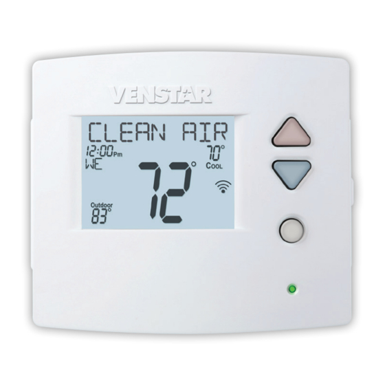
Get To Know Your Thermostat Backlit, Scrolling Display Backlit Cooler & Warmer Buttons Backlit LCD Display Override Button Heat or Cool Demand Indicator Red = Heat, Green = Cool Setup Buttons Behind Door... - Page 8 Get To Know Your Thermostat Setup Buttons...
- Page 9 Get To Know Your Thermostat Display Features Program ONOFF 2nd3rd 18:88 Unoccupied123 Stage Setup Step Override Fan On Outdoor Note : You may see 2nd/3rd illuminated even though you don’t have actual multistage equipment. This has NO EFFECT on your primary heating or cooling - it will run whether or not you see 2nd/3rd on the display Clock with Day of the Week—Indicates the current time and day.
- Page 10 Get To Know Your Thermostat Display Features Program ONOFF 2nd3rd 18:88 Unoccupied123 Stage Setup Step Override Fan On Outdoor 2nd and 3rd Stage icons Indicates what stage of cooling or heating is currently energized. Setup Step icon Indicates the step number when in advanced setup. Occupied &...
- Page 11 Get To Know Your Thermostat Display Features Program ONOFF 2nd3rd 18:88 Unoccupied123 Stage Setup Step Override Fan On Outdoor AuxHeat icon Indicates 2nd stage electric strip heat is being used when the thermostat is programmed for Heat Pump operation. Only the Aux icon will appear during Cool to Dehumidify to indicate Reheat operation.
-
Page 12: How To Use Your Thermostat
How to use your thermostat During Setup and Programming Press the WARMER or COOLER buttons to modify the selection. Press the MODE button to advance and confirm through the setup steps. Selecting the Heat or Cool Mode Select mode by pressing the MODE button. HEAT - Only the heating operation will be controlled by the thermostat in this mode. -
Page 13: Viewing Air Quality And Temperature Values
How to use your thermostat Viewing Air Quality and Temperature Values Press the SENSOR button to view the internal sensors and any optional remote sensors. The screens may appear as follows. Press MODE to advance to the next sensor, press SENSORS to exit this function. -
Page 14: Using The Override Button
How to use your thermostat Using the Override Button NOTE: Override may only be used when the thermostat is UNOCCUPIED OPERATION - set to PROGRAM ON. OVERRIDE During programmed, unoccupied periods, pressing the OVERRIDE button will force the thermostat into Occupied OUTDOOR 1 settings for 30 minutes. -
Page 15: Setting The Clock And Day
How to use your thermostat Setting the Clock and Day Not available when connected to the Skyport server Press the SET CLOCK button. Adjust the clock using the WARMER or COOLER buttons. Press MODE to advance to the day setting. Adjust the day using the WARMER or COOLER buttons. - Page 16 How to use your thermostat Programming a Daily Schedule Once the Set Program prompt appears the Mode button will step you through the settings. When selecting a Mode for Unoccupied/Occupied, options are OFF, HEAT, COOL, HEAT and COOL. These may be limited by the selection in setup step #2, AVAILABLE MODES.
-
Page 17: Air Patrol
Air Patrol Air Patrol continually samples the Indoor Air Quality (IAQ) at the thermostat. When Air Patrol is enabled and the Indoor Air Quality drops into the selected category: • The fan will turn on to circulate the air through the HVAC’s filtration system with a 5 minute minimum runtime •... - Page 18 Air Patrol Setup & Configuration Air Patrol is configured from Skyweb, Venstar’s Skyport web application. Select an Explorer-IAQ thermostat to configure the Air Patrol settings. Select the “3 vertical dots” Select “Settings” at the bottom in the top right corner.
- Page 19 Air Patrol Enable Air Patrol. When enabled Set the Air Patrol Duration. the Air Patrol. Threshold and This is the maximum the fan Duration settings will appear. is allowed to run per hour. If the Air Quality does not reach Set the Air Patrol Threshold at the next better IAQ level in this which Air Patrol will turn on the...
-
Page 20: Vennet Sensors
VenNet Sensors Pairing a Sensor Press and hold the PAIR button on the sensor for 1 second. a. Upon release of the PAIR button, the LED will flash twice. b. The sensor will remain in its pairing state for 1 minute. Move the sensor to within 3 inches of the thermostat. -
Page 21: Un-Pairing A Sensor
VenNet Sensors Un-Pairing any wireless Sensor Press the ACCESSORY STATUS button Press the COOLER button to view all wireless sensors, either VenNet or wifi sensors will be shown. ACCESSORY SET CLOCK STATUS SETUP ACCESSORY SETUP EMERGENCY HEAT HOLIDAY Press WARMER/COOLER buttons to select the sensor to be un-paired 1, 6 Press/hold FAN button for 2 seconds... -
Page 22: Setup Steps
*Some of the following settings are usually adjusted by the installer. It is acceptable to have any of these steps be adjusted by the user as well. Contact Venstar if you have further questions on the meaning of these settings Program Mode (Setup Step 1) This thermostat may be configured to be programmable or non programmable. -
Page 23: Backlight (On/Off, Intensity, Nighttime Dimming)
Setup Steps Press the SETUP button, then press MODE repeatedly until the WARMER desired setup step appears. Use the WARMER or COOLER buttons to make selection. Press MODE to advance to the next step. SETUP Press/hold MODE to go backwards to prior steps. Press SETUP to MODE COOLER leave the setup screens. -
Page 24: Heating And Cooling System Runtime - Energy Watch
Setup Steps Press the SETUP button, then press MODE repeatedly until the WARMER desired setup step appears. Use the WARMER or COOLER buttons to make selection. Press MODE to advance to the next step. SETUP Press/hold MODE to go backwards to prior steps. Press SETUP to MODE COOLER leave the setup screens. -
Page 25: Language (English, Spanish, French)
Setup Steps Press the SETUP button, then press MODE repeatedly until the WARMER desired setup step appears. Use the WARMER or COOLER buttons to make selection. Press MODE to advance to the next step. SETUP Press/hold MODE to go backwards to prior steps. Press SETUP to MODE COOLER leave the setup screens. -
Page 26: Setpoint Limits
Setup Steps Press the SETUP button, then press MODE repeatedly until the WARMER desired setup step appears. Use the WARMER or COOLER buttons to make selection. Press MODE to advance to the next step. SETUP Press/hold MODE to go backwards to prior steps. Press SETUP to MODE COOLER leave the setup screens. -
Page 27: Equipment Timers And Heat/Cool Spread
*Some of the following settings are usually adjusted by the installer. It is acceptable to have any of these steps be adjusted by the user as well. Contact Venstar if you have further questions on the meaning of these settings... -
Page 28: Deadbands And Interstage Timers
*Some of the following settings are usually adjusted by the installer. It is acceptable to have any of these steps be adjusted by the user as well. Contact Venstar if you have further questions on the meaning of these settings... -
Page 29: Minutes Of Fan Purge
Setup Steps Press the SETUP button, then press MODE repeatedly until the WARMER desired setup step appears. Use the WARMER or COOLER buttons to make selection. Press MODE to advance to the next step. SETUP Press/hold MODE to go backwards to prior steps. Press SETUP to MODE COOLER leave the setup screens. -
Page 30: Using A Wired Remote Sensor
Setup Steps Press the SETUP button, then press MODE repeatedly until the WARMER desired setup step appears. Use the WARMER or COOLER buttons to make selection. Press MODE to advance to the next step. SETUP Press/hold MODE to go backwards to prior steps. Press SETUP to MODE COOLER leave the setup screens. -
Page 31: Humidity Settings
Setup Steps Press the SETUP button, then press MODE repeatedly until the WARMER desired setup step appears. Use the WARMER or COOLER buttons to make selection. Press MODE to advance to the next step. SETUP Press/hold MODE to go backwards to prior steps. Press SETUP to MODE COOLER leave the setup screens. -
Page 32: Select Fahrenheit Or Celsius
Setup Steps Press the SETUP button, then press MODE repeatedly until the WARMER desired setup step appears. Use the WARMER or COOLER buttons to make selection. Press MODE to advance to the next step. SETUP Press/hold MODE to go backwards to prior steps. Press SETUP to MODE COOLER leave the setup screens. -
Page 33: Dry Contact Input (Polarity, Use)
Setup Steps Press the SETUP button, then press MODE repeatedly until the WARMER desired setup step appears. Use the WARMER or COOLER buttons to make selection. Press MODE to advance to the next step. SETUP Press/hold MODE to go backwards to prior steps. Press SETUP to MODE COOLER leave the setup screens. -
Page 34: Humidify / Dehumidify Outputs
Setup Steps Press the SETUP button, then press MODE repeatedly until the WARMER desired setup step appears. Use the WARMER or COOLER buttons to make selection. Press MODE to advance to the next step. SETUP Press/hold MODE to go backwards to prior steps. Press SETUP to MODE COOLER leave the setup screens. - Page 35 Setup Steps Press the SETUP button, then press MODE repeatedly until the WARMER desired setup step appears. Use the WARMER or COOLER buttons to make selection. Press MODE to advance to the next step. SETUP Press/hold MODE to go backwards to prior steps. Press SETUP to MODE COOLER leave the setup screens.
- Page 36 Setup Steps Press the SETUP button, then press MODE repeatedly until the WARMER desired setup step appears. Use the WARMER or COOLER buttons to make selection. Press MODE to advance to the next step. SETUP Press/hold MODE to go backwards to prior steps. Press SETUP to MODE COOLER leave the setup screens.
-
Page 37: Automated Demand Response
Skyport* (Setup Step 76) Set to ON to allow access to Skyport services or to OFF to not allow access to Skyport services. Visit venstar.com for more information. Local API* (Setup Step 77) Set to ON to allow third-party software to interface with your thermostat. -
Page 38: Locking/Unlocking The Buttons
Locking the Buttons Locking/Unlocking the Buttons To prevent unauthorized use of the thermostat, the front panel buttons may be disabled. To disable, or ‘lock’ the keypad, press and hold the MODE button. While holding the MODE button, press the WARMER and COOLER buttons together for 5 seconds. -
Page 39: Holiday
Holiday Feature Holiday The Holiday feature allows the thermostat to use temporary, energy saving settings without having to change regular HOLIDAY programming. Holiday setup/programming at the local thermostat is not allowed. In this case Holiday setup and programming is accomplished with the Skyport Web App. Skyport gives the user extensive control over Holiday settings. -
Page 40: Emergency Heat
Emergency Heat Emergency Heat The Emergency Heat function is only available EMERGENCY HEAT if your thermostat is set to control a Heat Pump. To initiate the Emergency Heat feature, Press the EMERGENCY HEAT button. During Emergency Heat operation the thermostat will turn on the fan and auxiliary stages of heat when there is a demand for heat. -
Page 41: Calibration
Calibration Under normal circumstances it will not be necessary to adjust the calibration of the termperature or humidity sensors. If calibration is required, please contact a trainsed HVAC technician to correctly perform the folowing procedure. Press and hold SETUP for 10 seconds. All icons will appear on the display. -
Page 42: Restoring Factory Default Settings
Restoring Factory Default Settings Resetting the Thermostat to the Factory Default Settings (for default values see page 48, Advanced Setup Steps Table) If, for any reason, you desire to return all the stored settings back to the factory default settings, follow the instructions below. WARNING: This will reset all Time Period and Advanced Programming to the default settings. -
Page 43: Test Outputs And Calibrate Temperature Sensor
Installation Instructions Test Operation The thermostat has a diagnostic feature that enables testing of all outputs. This feature is contained in the thermostat’s technician setup. To enter Technician Setup, press and hold the SETUP button for 10 seconds until all the icons appear. Follow the next steps to view settings and test equipment. 1. -
Page 44: Installation Instructions
Installation Instructions Remove and Replace the old thermostat To install the thermostat properly, please follow these step by step instructions. If you are unsure about any of these steps, call a qualified technician for assistance. • Assemble tools: Flat blade screwdriver, wire cutters, wire strippers and phone camera. - Page 45 Installation Instructions Wire Connections If the terminal designations on your old thermostat do not match those refer to the chart below or the wiring on the new thermostat, diagrams that follow. Wire from the Install on the old thermostat Function new thermostat terminal marked connector marked...
- Page 46 Installation Instructions The Explorer-IAQ Thermostat Backplate To remove the thermostat backplate: Gently separate the display from the base by pulling first from one side, then the other until the two pieces unsnap. A small screwdriver may be used, very carefully, to start seperating the two pieces.
- Page 47 Installation Instructions Check Dip Switch Ensure which switch is correct for your system. Dip switches are located on the back of the thermostat. 1. When GAS/EL or HP is set for GAS/EL: This switch (GAS or ELEC) controls how the thermostat will control the Fan (G) terminal in heating mode.
- Page 48 Installation Instructions Sample Wiring Diagrams Conventional Heating and Cooling Systems 3 Wire, Heat Only 4 Wire, Cool Only Residential & Commercial 1 Stage Heating Residential & Commercial 1 Stage Cooling. with no Fan. 24VAC Power 24VAC Power 24VAC Common 24VAC Common 1st Stage Cool W1/O/B 1st Stage Heat...
- Page 49 Installation Instructions Sample Wiring Diagrams Heat Pump Systems 5 Wire, 1 Stage Cooling, 1 Stage Heat 6 Wire, 1 Stage Cooling, 2 Stage Heat Residential & Commercial Heat Pump with Residential & Commercial Heat Pump with O Reversing Valve O Reversing Valve 24VAC Power 24VAC Power 24VAC Common...
- Page 50 Installation Instructions Sample Wiring Diagrams Heat Pump Systems with Dual Fuel Humidification or Dehumidification Humidification Humidification or Dehumidification System Humidification W1/O/B OUTDOOR System SENSOR Dehumidification Terminal REMOTE W1/O/B OUTDOOR SENSOR on Equipment SENSOR REMOTE Dehumidification Terminal CONTACT DEHUM/ SENSOR on Equipment DEHUM CONTACT DEHUM/...
-
Page 51: Technician Setup
Technician Setup To enter Technician Setup, press and hold the SETUP button for 10 seconds. After all the icons appear, press MODE. The version number of the thermostat will appear in the scrolling text. Press MODE to advance to the next step. Use the WARMER or COOLER buttons to adjust the value of your selection. -
Page 52: Troubleshooting
Troubleshooting • SYMPTOM: The air conditioning does not attempt to turn on. CAUSE: The compressor timer lockout may prevent the air conditioner from turning on for a period of time. REMEDY: You might want to change the Compressor Minimum Off Minutes to 0 in Setup Step 26. -
Page 53: Advanced Setup Table
Advanced Setup Table Df = Factory Default Setting Step# Description Pg# Range Prog Mode Non, 7 Day Available Modes Heat/Cool/Auto/Off, Heat/Cool/Off, Heat/Cool/ Heat/Off, Cool/Off Auto/Off Backlight On, Off Backlight Level Off through 7 levels of brightness Level 5 Night Dimmer On/Off Night Dimmer Brightness Off through 7 levels of brightness 2 (20%) - Page 54 Advanced Setup Table Df = Factory Default Setting Step# Description Range 3rd StageTurnoff Point Deadband, Setpoint Deadband 4th Stage Turnoff Point Deadband, Setpoint Deadband Minutes of Fan Purge 0 - 3:00, 15 min. incre. - 0 = off Wired Sensor Type Remote, Supply, Outdoor Remote Control to Temp Source...
- Page 55 Advanced Setup Table Df = Factory Default Setting Step# Description Range Cool Setpoint Offset 1 to 15 Heat Setpoint Offset -1 to -15 IAQ Air Patrol enabled, disabled disabled Air Patrol On If IAQ Exceeds Moderate, Poor Moderate Moderate Quality Air Patrol Fan On Minutes 5 - 60 Skyport...
-
Page 56: Warranty
Warranty One-Year Warranty - This Product is warranted to be free from defects in material and workmanship. If it appears within one year from the date of original installation, whether or not actual use begins on that date, that the product does not meet this warranty, a new or remanufactured part, at the manufacturer’s sole option to replace any defective part, will be provided without charge for the part itself provided the defective part is returned to the distributor through a qualified servicing dealer. - Page 57 Patent Pending P/N 88-1448 Rev. 2 01/18/22...
Need help?
Do you have a question about the T4950-IAQ and is the answer not in the manual?
Questions and answers