
Related Manuals for Digital Dream DDCS V2.1


Summary of Contents for Digital Dream DDCS V2.1
- Page 1 Standalone Motion Controller DDCS V2.1 User’s Guide Digital Dream CNC Co,. Ltd. www.ddcnc.com...
-
Page 2: Introduction Of Product
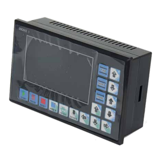
The DDCS V2.1 can be used for many styles and types of CNC machines. Lathes, Routers, Pick&Place and Mills are just a few examples. The DDCS V2.1 operates as a Stand Alone system without the need of a comput- er. This guarantees high precision, accuracy and reliability. The interface, even very comprehensive, can be learned in a very short time. - Page 3 1.3 Appearance, Structure and Size of Product The DDCS V2.1 is a small box that can fit in a window of a small control box or control cabinet. Two locking hooks fix this controller from the inside. The dimension you find in picture 1-1 and picture 1-2.
- Page 4 USB input. Please see the reference picture 1-3 and picture 1-4 in detail. 4.3'' Screen 17 user’s keys Picture1-3 Front panel Stepper/ Power Supply Input Ports Servo Ports MPG Ports 18~24VDC Spindle&output Ports USB Port Picture 1-4 Rear view Digtital Dream 4 Axis Motion Controller Page -3 DDCS V2.1 User’s Manual...
-
Page 5: Explanation Of Abbreviations
1.4 Explanation of Abbreviations When operating the DDCS V2.1, the users will come across some English abbreviations. Here a list with explanations FRO: Feed Rate Override SRO: Spindle Rate Override SRJ: Jog Speed Setting F: Feed rate, unit is mm/min S: Spindle Speed, unit rev/min. - Page 6 Wiring and Ports As the picture shows, the wiring section of the controller has Input Ports,Spindle&Output Ports,tepper/Ser- vo control step and direction output,MPG Port, USB Port and Power supply Port. Digtital Dream 4 Axis Motion Controller Page -5 DDCS V2.1 User’s Manual...
-
Page 7: Power Supply Wiring
This USB port is the standard USB A-type. A 50cm USB extension cord with installation plug is supplied with the controller. See sketch diagram picture 2-4 for reference. Picture 2-4 USB interface extension cord Digtital Dream 4 Axis Motion Controller Page -6 DDCS V2.1 User’s Manual... - Page 8 MPG A phase differential input positive terminal ground MPG ground MPG power supply reference ground. MPG serial communication output Used for digital display of the MPG Table 2-1 Cr8-500’s MPG Port Digtital Dream 4 Axis Motion Controller Page -7 DDCS V2.1 User’s Manual...
- Page 9 +5V-W Table 2-2 Differential MPG and DDCS V2.1 wiring mode Note: It you want to use the single-terminal MPG (there is no A-B-MPG), please refer to table 2-3 for reference. As for the unlisted MPG, please take the differential MPG wiring mode.
- Page 10 A axis pulse A axis pulse signal negative terminal Direction A- A axis direction A axis direction signal negative terminal Table 2-4 DDCS V2.1 stepper/servo control interface definition Digtital Dream 4 Axis Motion Controller Page -9 DDCS V2.1 User’s Manual...
- Page 11 Note: Some VFD’s have the ground for 0-10V Output ground and the input signal FWD separate. In those cases both grounds need to be connected. Table 2-5 DDCS V2.1 VFD wiring Digtital Dream 4 Axis Motion Controller Page -10 DDCS V2.1 User’s Manual...
- Page 12 Probe, Limit/Home and E-Stop. Home and Limit switches can be NO or NC, the parameters can be set accord- ingly in the Parameter Page. Picture 2-9 ESTOP, LIMIT and PROBE input signal circuit Digtital Dream 4 Axis Motion Controller Page -11 DDCS V2.1 User’s Manual...
-
Page 13: External Buttons
+12V Pause Probe Limit X+ Home X Limit Y- Limit Z+ Start Estop +12V Limit X- Limit Y+ Home Y Hom Picture 2-11 Wiring of Limit X+ switch Digtital Dream 4 Axis Motion Controller Page -12 DDCS V2.1 User’s Manual... - Page 14 Start Estop +12V Limit X- Limit Y+ Home Y Home Z- Limit A+ Home A Picture 2-13 Wiring of Limit X+ switch Limit A- t A+ Home A Digtital Dream 4 Axis Motion Controller Page -13 DDCS V2.1 User’s Manual...
- Page 15 Limit X- Limit Y+ H Picture 2-14 Wiring of the Probe Limit/home general micro switch or wiring mode of 2-line Inductive proximity switch: Picture 2-15 Inductive proximity switch wiring mode Digtital Dream 4 Axis Motion Controller Page -14 DDCS V2.1 User’s Manual...
-
Page 16: Interface Description
Picture 3-1 Main page The picture 3-1 shows the Main page of the DDCS V2.1. It is divided into status column, coordinate display column, basic parameter column, and notification column. In total, it is divided into 18 sections in detail. Here the detailed description of the 18 sections : 1、X Coordinate... - Page 17 Z+: Cancel 8 Coordinate System With the DDCS V2.1 control panel it is very easy to control your Machine Coordinates and Work Offset Coordinates. Click FRO/SRO/SJR (from now on only called FRO) 6 times until the coordinate system is highlighted. Here you can display G54 to G59 and MACH (Machine Coordinates) by clicking A+ and A- After selecting a function with the FRO key you use the A+ button to Select and the button to Modify the value.
- Page 18 CONT: indicates Jog CONTINUOUS. You can Jog manually with the “-”or “+” keys of X Y Z and A. A short click will move the axis in the defined step, a long click will move the axis till you let go Step: Jogging in Step Mode Digtital Dream 4 Axis Motion Controller Page -17 DDCS V2.1 User’s Manual...
- Page 19 Each parameter has a specific number, the parameter can be modified . 2. Parameter Name The definition of the Parameter is listed in the Parameter Name column. All Parameters are divided into groups according to their function. Digtital Dream 4 Axis Motion Controller Page -18 DDCS V2.1 User’s Manual...
-
Page 20: Definition Of Keys
The Parameter Unit lists the unit of each parameter. Definition of Keys Picture 3-4 Keys Layout The picture 3-4 shows the key layout of the DDCS V2.1. The Controller DDCS V2.1 has 17 keys. Please see table 3-1 for reference. Keys Icon Function No. Definition... - Page 21 When in READY, this key changes the Jog mode 1:mod switch from Continuous to Step and MPG control. 2:file delete In File Management it is the DELETE key Table 3-1 List of Keys’ function Digtital Dream 4 Axis Motion Controller Page -20 DDCS V2.1 User’s Manual...
- Page 22 Main Page for processing. If the blue bar highlights a .set file, it will upgrade the system. In this case make sure you delete the settings file or the upgrade will overwrite the original settings file too and you will lose your settings. Digtital Dream 4 Axis Motion Controller Page -21 DDCS V2.1 User’s Manual...
- Page 23 Choose your target directory or target folder, click to paste the 2mmnew.tap file to this directory. See picture 3-8 for reference Picture 3-8 Paste the 2mmnew.tap file to this directory Digtital Dream 4 Axis Motion Controller Page -22 DDCS V2.1 User’s Manual...
- Page 24 . The file will be loaded and the screen will change back to the Main Screen for processing. The file name will be displayed. Picture 3-11 Search for the file2mmnew.tap Digtital Dream 4 Axis Motion Controller Page -23 DDCS V2.1 User’s Manual...
- Page 25 526 . The controller now is in BUSY Mode. Press to switch the display to show the tool path. Picture3-14,15 and 16 show the tool path display. Digtital Dream 4 Axis Motion Controller Page -24 DDCS V2.1 User’s Manual...
- Page 26 Picture 3-13 G code processing Picture 3-14 Tool path display after processing about half the file Picture 3-15 Tool path display after processing most of the file Digtital Dream 4 Axis Motion Controller Page -25 DDCS V2.1 User’s Manual...
- Page 27 Insert the line number and click . A syntax check will be performed and the G code will be operated from your chosen Start Line position See pictures 3-17 to 3-19. Digtital Dream 4 Axis Motion Controller Page -26 DDCS V2.1 User’s Manual...
- Page 28 Picture 3-17 Edit the start line Picture 3-18 Syntax Checking Picture 3-19 Program will run from the chosen line Digtital Dream 4 Axis Motion Controller Page -27 DDCS V2.1 User’s Manual...
- Page 29 S J R a n d m o d i f y t h e j o g s p e e d w i t h a n d . A l l o t h e r a x e s c a n be moved in the same way. Digtital Dream 4 Axis Motion Controller Page -28 DDCS V2.1 User’s Manual...
- Page 30 0% to 300% 2) SRO The Spindle adjustment controls the spindle’s speed. Highlight SRO and use adjust the spindle speed from 0% to 200% Digtital Dream 4 Axis Motion Controller Page -29 DDCS V2.1 User’s Manual...
- Page 31 F. If you click an Edit Window will appear Choose your desired Feed speed and confirm with Enter. See picture 3-23 Picture 3-23 Enter default F modification mode Digtital Dream 4 Axis Motion Controller Page -30 DDCS V2.1 User’s Manual...
- Page 32 ….G59 or MACH (stands for Machine Coordinates). to choose your desired Coordinate System. Position values will be displayed for X, Y, Z and A. The Enter key confirms the Coordinate System you chose. Digtital Dream 4 Axis Motion Controller Page -31 DDCS V2.1 User’s Manual...
- Page 33 X Y and Z will show 0.000 Picture 3-26 The tool tip over the work piece center Tip: Do not forget to probe again after a tool change Digtital Dream 4 Axis Motion Controller Page -32 DDCS V2.1 User’s Manual...
-
Page 34: Parameter Setting
You can modify all the parameters in the Parameter Page but also within the setting.set file. Originally the DDCS V2.1 will be loaded with the default setting and you can change the settings in the Parameter Page (or in the text file setting.set) to adjust for your machine. - Page 35 Please use the setting value of default parameter under the situation of not understanding the actual function of this parameter. Digtital Dream 4 Axis Motion Controller Page -34 DDCS V2.1 User’s Manual...
- Page 36 This value cannot be negative value Operation acceleration 0~2000 mm/min #435 Max speed of X axis mm/min 0~20000 8000 #436 Max speed of Y axis 8000 mm/min 0~20000 Digtital Dream 4 Axis Motion Controller Page -35 DDCS V2.1 User’s Manual...
- Page 37 Z after home 0~1000 The parameter of this group back off distance of A after home 0~1000 is this back off distance Digtital Dream 4 Axis Motion Controller Page -36 DDCS V2.1 User’s Manual...
- Page 38 The limit values refer to the machine coordinates, not the work piece coordi- #381 value Z++ Soft Limit BOOL 0~2000 nate. #382 value A++ Soft Limit BOOL 0~2000 Digtital Dream 4 Axis Motion Controller Page -37 DDCS V2.1 User’s Manual...
- Page 39 Mode of deaw tool road: As for the plane line, such as the PCB engraving or the color plates lettering, please adopt the line pattern. As for the plane embossment, please adopt the statue pattern. Digtital Dream 4 Axis Motion Controller Page -38 DDCS V2.1 User’s Manual...
-
Page 40: Firmware Upgrade
Decompress the downloaded file onto a USB disk, direct into the root directory (not inside a folder). The file after decompressing will look like in picture 3-32 Picture 3-32 Position of Firmware version number Digtital Dream 4 Axis Motion Controller Page -39 DDCS V2.1 User’s Manual... - Page 41 After you copied the install file to the USB key, insert the USB into the controllers USB port and then supply power to the controller. The update will be performed automatically and the screen will not change for about 30 seconds. Please be patient. Digtital Dream 4 Axis Motion Controller Page -40 DDCS V2.1 User’s Manual...
- Page 42 Screen displayed during upgrade process (approx 30 seconds) Picture 3-36 After the upgrade finished, the main page will be displayed. Check the version number After the upgrade, the DDCS V2.1 can be used right away. Digtital Dream 4 Axis Motion Controller Page -41...
Need help?
Do you have a question about the DDCS V2.1 and is the answer not in the manual?
Questions and answers
I purchased a DDSC V2.1EXPERT How can I change the unit from metric to inches"inperial"
To change the unit from metric to inches on the Digital Dream DDCS V2.1:
1. Set Parameter #115 (unit selection) to "1" for inches.
2. Use “G20” in your program’s safety line to specify inch mode.
Note: The display may still show "mm", as the controller does not automatically update the display label. A manual label or sticker may be used to indicate readings are in inches.
This answer is automatically generated