
Related Manuals for Digital Dream UC300


Summary of Contents for Digital Dream UC300
- Page 1 The version of 20180925 Mach3 USB Motion Controller UC300 User’s Manual Digital Dream CNC Co,. Ltd. www.ddcnc.com...
-
Page 2: Table Of Contents
C on t e n t s 1. Brief Description of the UC300 Motion Controller ● ● ● ● ● ● ● ● ● ● ● ● ● ● ● ● ● ● ● ● ● ● ● ● ●... -
Page 3: Brief Description Of The Uc300 Motion Controller
USB Port. The computer connects to the UC300 via a standard USB cable.It’s the best to shiled the communication USB cable to ignore the interferences. -
Page 4: Physical Installation Of The Device
3. Physical Installation of the device(Unit:mm) The UC300 motion controller is with the sealed shell structure,there are 4pcs mounting holes around the controller.We can fix 4pcs 4mm diameter holes at the cabinet,and install the controller into the cabinet. 21 mm... - Page 5 4. Controller UC300 Power supply Solution The power supply solution in the field of the Industrial automation is always very complicated, there is a lot of the GND, now we descript the structure of the power structure as below: The power structure as the Picture 4-1,Power supply input and USB port share common GND, stepper control module,Input&Output module,Spindle control module and MPG Port share common GND, between the...
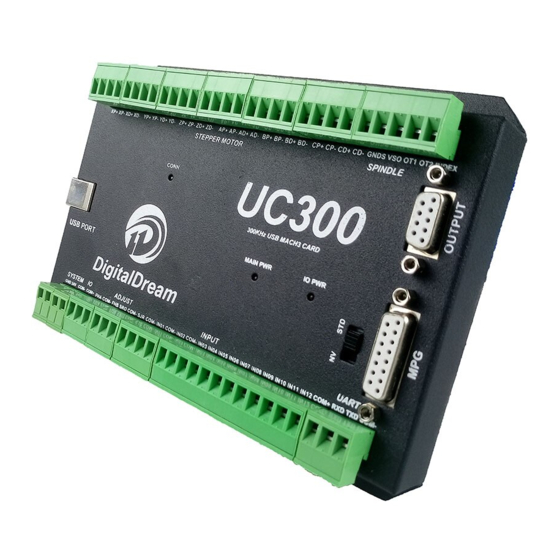
- Page 6 3 : Spindle Control Output Port 4 : Gerneral Output Interface 5 : MPG Port 6 : Functional Switch for MPG:Standard MPG or Digital Dream MPG 7 : Serial Extend Port 8 : Input Port:Limit/Home/Probe and so on 9 : Adjustable parameter Input Port...
-
Page 7: Stepper/Servo Motor Control Interface Connection
5.1 USB Communication Port to PC To setup the connection between the controller and the Mach3 software on computer,UC300 use the USB port,as the Marked No.1 on Picture 5-1. 5.2 Stepper/Servo Motor Control Interface Connection As the Marked No. 2 from Picture 5-2,there is the Stepper/Ser- vo Interface.The device can be used to control machine tools... -
Page 8: Spindle Control Output Port
For example if we set the Max Speed is 24000,and we need the current spindle speed is 18000,then VSO=10*18000/24000=7.5V. The following picture 5-7 is the setting method of Max. speed in Mach3 software. Digital Dream Mach3 Motion Controller Page -6 UC300 User’s Manual... -
Page 9: General Output Interface
Picture 5-4 UC300 Spindle Motor Max Speed Setting 5.4 General output interface As the Picture 5-1 showed. the marked No. 4 is General output interface. This is a DB9 port. Picture 5-5 General Output Interface PIN No. Mark Definition Common Ground for output... - Page 10 Picture 5-6,it is the controller supply the power for the Output Ports.If the users want to supply the external power for the relay,then the connection is between GND(Pin1) and Output4(Pin2). GND is COM-. OUT4 COM+ Picture 5-7 Solid Replay Connection Digital Dream Mach3 Motion Controller Page 8 UC300 User’s Manual...
- Page 11 As the Picture 5-1 showed, the marked No.6 is the switch for the options of two type MPG.For EC500,it can supply both standard MPG and NV-MPG which is made by our company Digital Dream. The Marked No. 5 is the interface for the connection of MPG.
-
Page 12: Serial Extend Port
3 lines Proximity Switch connection Picture 5-11 and Picture 5-12, brown cable for Proximity switch connect with COM+,Black cable connect channel, blue cable connect with COM-. Pls note Only support NPN typel 3 lines proximity switch. Picture 5-9 Internal structure of Input interface Digital Dream Mach3 Motion Controller Page -10 UC300 User’s Manual... - Page 13 Picture 5-10 Probe/Estop/ and other switch input connection Picture 5-11 Probe/Estop/ and other switch input connection Picture 5-12 NPN 3 lines Proximity Switch Connection Example Digital Dream Mach3 Motion Controller Page -11 UC300 User’s Manual...
-
Page 14: Adjustable Input Interface
‘Feed rate override’.When there is connection between COM- and SRO,it is in the terms of ‘Spindle speed rate override’;if there is connection between COM- and SJR,it is in the term of ‘Jog Mode’. Digital Dream Mach3 Motion Controller Page -12 UC300 User’s Manual... -
Page 15: Power Supply For Controller System And Power Supply For Io Port
If the controller and IO power supply are configurated in right way,the Main Power LED and IO Power LED turn to Red. The LED marked “CONN” represents the status of the communicaton with Mach3 software.If a link has not been established,the LED will not light. Digital Dream Mach3 Motion Controller Page -13 UC300 User’s Manual... -
Page 16: Mach 3 Configuration
Double-click the icon mach3mill .Enter into Mach3 software. Pop-up the plug-in box as below left picture.Then Click “Create Profile” and name it to “DigitalDream”,click “Default profile values” and confirm it by “OK” Digital Dream Mach3 Motion Controller Page -14 UC300 User’s Manual... -
Page 17: Check Uc300 Plug-In In The Mach3 Software
After Click “OK”,it will popup a window of the option for DLL file as below,pls choose “Digital Dream” as below.Then press OK. If you do not want to the dialog box to show again any more, select ‘Don’t ask me this again’.If connect successfully,Status bar will show “EC500 device is connected to your computer”. -
Page 18: Motor Tuning And Setup
Don’t forget to save the data when you finished the data setting of every axis.For example,you click Z Axis,and save all the datas into the column,then you must click “SAVE AXIS SETTING”,then the datas can be saved. Digital Dream Mach3 Motion Controller Page -16 UC300 User’s Manual... - Page 19 Our EC500 controller has plenty of inputs available and it allows Mach to home all of your axes at the same time if you wish (although you typically have your Z axis home after the rest of your axes so you don't crash your head). Digital Dream Mach3 Motion Controller Page -17 UC300 User’s Manual...
- Page 20 Here you can configure according to your actual needs the corresponding function. Optional Function include XYZABC 6axis’s Upper and lower limit、XYZABC 6axis’s HOME point. We set upper limit and home of XYZA to 3456 corresponding IN3/IN4/IN5/IN6 of the Controller board. Digital Dream Mach3 Motion Controller Page -18 UC300 User’s Manual...
- Page 21 Here by our controller we already define all the Output Ports to Port No. 2. All Output Ports are defined to Port No. 2. Spindle setting corresponds to the output configuration Digital Dream Mach3 Motion Controller Page -19 UC300 User’s Manual...
-
Page 22: Mpg Settings
Then the following windown will popup,click the “CONFIG” of the DigitalDream dll as following,there will be the selection windows for NV-MPG and standard MPG.The user have to select the right MPG type as their request. Digital Dream Mach3 Motion Controller Page -20 UC300 User’s Manual... - Page 23 Go to Mach 3 and Menu -> Config -> Ports & Pins -> Encoder/MPG’s as following. Then to active the MPG function, you can use the hand pulse, under the main page, click TAB to active MPG panel, refer to the following Picture: Digital Dream Mach3 Motion Controller Page -21 UC300 User’s Manual...
Need help?
Do you have a question about the UC300 and is the answer not in the manual?
Questions and answers