Table of Contents

Related Manuals for Digital Dream DDCS V3.1


Summary of Contents for Digital Dream DDCS V3.1
- Page 1 Standalone Motion Controller Users Manual V3 Software Version No. 2019-04-25-107NOR All copyrights reserved Shall not be reproduced without permission. 深 圳 市 众 联 拓 数 控 科 技 有 限 公 司 Shenzhen Digital Dream Numerical Technology Co., Ltd.
-
Page 2: Table Of Contents
● ● ● ● ● ● ● ● ● ● ● ● ● ● ● ● ● ● ● ● ● ● ● ● ● ● ● Digital Dream Standalone Motion Controller DDCS V3.1 Page -1 DDCS V3.1 Users Manual... - Page 3 ● ● ● ● ● ● ● ● ● ● ● ● ● ● ● ● ● ● ● ● ● ● ● ● ● ● ● Digital Dream Standalone Motion Controller DDCS V3.1 Page -2 DDCS V3.1 Users Manual...
-
Page 4: Ddcs V3.1 Controller Brief Introduction
The DDCS is a 3~4 axes motion controller for stepper and servo systems. DDCS V3.1 is updat- ed from DDCS V2.1 on software and hardware.We are very proud of this product, it combines great power with a tiny footprint and is easy to use. -
Page 5: Ddcs V3.1 Brief Technical Feature
13) Support for “Power Cut” recovery. Data is automatically saved; 14) Backlash compensation, Tool compensation DDCS V3.1 New features compared to previous version: 1) Control System Unit is compatible with Metric Units and Imperial Units; 2) MPG and extended Keyboard can also control and edit the controller system;... -
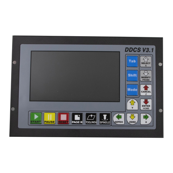
Page 6: Appearance, Structure And Size Of Product
1.3 Appearance, Structure and Size of Product The DDCS V3.1 is a small box that can fit in a window of a small control box or control cabi- net. Four locking hooks fix this controller from the frame. The dimension you find in Figure 1-1 and Figure 1-2. - Page 7 The 8 screws are to fix the wiring ternimal and controller. The USB Stick is for the transfer of the G-code file. Figure 1-4 Back side of the controller and the accessories Digital Dream Standalone Motion Controller DDCS V3.1 Page -6 DDCS V3.1 Users Manual...
-
Page 8: Explanation Of Abbreviations
E-stop at once to avoid damage to humans, animals and the equipment. High voltage danger. The DDCS is connected to 24V DC. Obey and follow the electrici- ty safety rules of your country when connecting this equipment. Digital Dream Standalone Motion Controller DDCS V3.1 Page -7 DDCS V3.1 Users Manual... -
Page 9: Wiring
The M3/M8/M10 digital output ports pull to ground. Figure 2-1 Power supply System structure 2.2 Product Wiring Overview MPG Ports USB Port Start/Pause/Estop Switch Figure 2-2 Wiring and Ports Digital Dream Standalone Motion Controller DDCS V3.1 Page -8 DDCS V3.1 Users Manual... -
Page 10: Start/Pause/Estop Switch Wiring
This USB port is the standard USB A-type. A 50cm USB extension cord with installation plug is supplied with the controller. See the diagram Figure 2-5 for reference. Figure 2-5 USB interface Digital Dream Standalone Motion Controller DDCS V3.1 Page -9 DDCS V3.1 Users Manual... -
Page 11: Mpg Port
Connect with GND, indicates selecting10 X, open indicates no pulse ESTOP ESTOP of MPG Connect with GND, indicate ESTOP is in effect.Open indicates Estop is invalid. Table 2-1 DDCS’s MPG Port Digital Dream Standalone Motion Controller DDCS V3.1 Page -10 DDCS V3.1 Users Manual... - Page 12 As for the unlisted MPG, please take the differential MPG wiring mode. DDCS Wiring Pin Mark MPG Pin Mark and Color Green WHA+ Black WHA- White WHB+ Black WHB- Table 2-3 DDCS Wiring with Single-terminal MPG Digital Dream Standalone Motion Controller DDCS V3.1 Page -11 DDCS V3.1 Users Manual...
-
Page 13: Main Port Wiring
fies the wiring. Please note in Figure 2.8, at the 4 corners, there are screws to lock the terminal to the controller. Figure 2-8 Main Port with wiring terminal Digital Dream Standalone Motion Controller DDCS V3.1 Page -12 DDCS V3.1 Users Manual... - Page 14 PIN 37 PIN 20 PIN 1 PIN 1 COM+ COM- COM- The Pin No. is DB37 interface Pin No. Table 2-4 Main Port Pin No. and Mark Page -13 Digital Dream Standalone Motion Controller DDCS V3.1 DDCS V3.1 Users Manual...
- Page 15 All between “COM+”s are conducting.All between “COM-”s are conducting. PIN 1 COM- Between COM+ and COM- there is 24VDC power.COM- is Negative side. Table 2-5 Main Port Pin No. and definition Page -14 Digital Dream Standalone Motion Controller DDCS V3.1 DDCS V3.1 Users Manual...
-
Page 16: Spindle Control Output
PIN3(M8),PIN22(M10) and PIN21(M3) is also can be used for OUTPUT ports.For example,it can be used for a Relay output port.For example the Figure 2-10 shows the wiring methods: PIN20:COM+ PIN22:M10 Figure 2-10 Wiring Methods with Relay Page -15 Digital Dream Standalone Motion Controller DDCS V3.1 DDCS V3.1 Users Manual... -
Page 17: Limit, Home And Probe Inputs,And The Power For The Input
The following wiring Figures and circuit Figures will show the connection of the Limit,Home and Probe Wiring. Figure 2-11 LIMIT,HOME and PROBE input signal circuit COM- X++ Limit Figure 2-12 The Limit wiring at X++ direction with mechanical limited switch Page -16 Digital Dream Standalone Motion Controller DDCS V3.1 DDCS V3.1 Users Manual... - Page 18 3-line proximity switch Figure 2-13 The Limit wiring at X++ direction with 3-line Inductive proximity switch Figure 2-14 The circuit of COM- PROBE Figure 2-15 The Probe Wiring Digital Dream Standalone Motion Controller DDCS V3.1 Page -17 DDCS V3.1 Users Manual...
-
Page 19: Stepper/Servo Control Output
2.6.3 Stepper/Servo Control Output The stepper/servo control output,we cite differential Pulse and Direction output method,Max. 500Khz per axis.DDCS V3.1 there is 3 or 4 axis for option PIN 18 (AD-),PIN 36 (AD+),PIN 17 (AP-),PIN 35 (AP+) is A Axis Control Output Pins;... -
Page 20: Power Supply Input
2.6.4 Power Supply Input DDCS V3.1 needs two power supplies,Main power is for system,IO Port is for Input and Output ports. Both power supply is 24VDC,current is not less then 1A.In the Main port inter- face,the marked 24V and GND is the main power input ports;the COM+ and COM- is the IO power input ports.Please keep in mind,only when the two power supplies are connected correctly the... -
Page 21: Software And Operation
This column shows the current coordinate value of X. The display range is -99999.999~+99999.999 in mm; 2、 Y Coordinate This column shows the current coordinate value of Y. The display range is -99999.999~+99999.999 in mm; Digital Dream Standalone Motion Controller DDCS V3.1 Page -20 DDCS V3.1 Users Manual... - Page 22 Coordinates. Click FRO/SRO/SJR (from now on only called FRO) 6 times until the coordinate system is highlighted. Here you can display G54 to G59 and MACH (Machine Coordinates) by clicking A+ and A- Digital Dream Standalone Motion Controller DDCS V3.1 Page -21 DDCS V3.1 Users Manual...
- Page 23 When in Step Mode, A+ and A- can change between the 4 distances set by #2020,#2021,#2022,#2023. When in MPG mode you can use the MPG to jog the machine Second Option: Jog a defined distance Digital Dream Standalone Motion Controller DDCS V3.1 Page -22 DDCS V3.1 Users Manual...
- Page 24 MPG: MPG mode. MPG takes over Jog control 2nd: 2nd mode. In 2nd mode you can choose all functions displayed in window 7 19、 Mach Coordinate This Window shows the Machine coordinate values. Digital Dream Standalone Motion Controller DDCS V3.1 Page -23 DDCS V3.1 Users Manual...
-
Page 25: File Management Page
Note:For the file selection,you can also use the MPG and USB Keyboard to turns and find out if the file list is too long. Digital Dream Standalone Motion Controller DDCS V3.1 Page -24 DDCS V3.1 Users Manual... -
Page 26: Parameter Page
4. Parameter Unit The Parameter Unit lists the unit of each parameter. Note:For the Parameter selection,you can use the USB keyboard and MPG to find the files quickly. Digital Dream Standalone Motion Controller DDCS V3.1 Page -25 DDCS V3.1 Users Manual... -
Page 27: Definition Of Keys
Press this key to manually switch the spindle on or Spindle manual start/close off. Can not be used if Reset is blinking and while processing an operation (Busy) SPINDLE Digital Dream Standalone Motion Controller DDCS V3.1 Page -26 DDCS V3.1 Users Manual... - Page 28 When in READY, this key changes the Jog mode 1:mod switch Mode from Continuous to Step and MPG control. 2:file delete In File Management it is the DELETE key Table 3-1 List of Keys’ function Digital Dream Standalone Motion Controller DDCS V3.1 Page -27 DDCS V3.1 Users Manual...
-
Page 29: Operation Of Common Functions
.set file, it will upgrade the system. In this case make sure you delete the settings file or the upgrade will overwrite the original settings file too and you will lose your settings. Digital Dream Standalone Motion Controller DDCS V3.1 Page -28... - Page 30 Choose your target directory or target folder, click to paste the 2mmnew.tap file to this directory. See Figure 3-9 for reference Figure 3-9 Paste the 2mmnew.tap file to this directory Digital Dream Standalone Motion Controller DDCS V3.1 Page -29 DDCS V3.1 Users Manual...
- Page 31 . The file will be loaded and the screen ENTER HOME will change back to the Main Screen for processing. The file name will be displayed. Figure 3-12 Search for the file2mmnew.tap and load Digital Dream Standalone Motion Controller DDCS V3.1 Page -30 DDCS V3.1 Users Manual...
-
Page 32: Running A G Code File
Y Axis and an EDIT WINDOW will open. Click to Zero Y. ENTER HOME Before starting the G-code the user must set the tool to the correct height and Zero the Z axis. Digital Dream Standalone Motion Controller DDCS V3.1 Page -31 DDCS V3.1 Users Manual... - Page 33 Figure3-14,15 and 16 show the tool path display. Figure 3-14 G code is processing Figure 3-15 Tool path display after processing at beginning the file Digital Dream Standalone Motion Controller DDCS V3.1 Page -32 DDCS V3.1 Users Manual...
-
Page 34: Breakpoint Operation
As the Figure 3-18 shows, it begins processing from the 255 line at this time. Figure 3-18 shows the display under the “goto break” status and the display shows the file name. Digital Dream Standalone Motion Controller DDCS V3.1 Page -33 DDCS V3.1 Users Manual... -
Page 35: Start A G Code File From A Specific Line
G code will be operated from your chosen Start Line position See Figures 3-19 to 3-21. Figure 3-19 Edit the start line Figure 3-20 Syntax Checking Digital Dream Standalone Motion Controller DDCS V3.1 Page -34 DDCS V3.1 Users Manual... -
Page 36: Pause In Operation
You can manually position the machine at any position. You can move Continuously, in defined Steps or with the MPG. The button moves you through the three options: Mode Digital Dream Standalone Motion Controller DDCS V3.1 Page -35 DDCS V3.1 Users Manual... -
Page 37: Manual Step Of The X Axis 3
. A l l o t h e r a x e s c a n be moved in the same way. MODIFY PROBE Digital Dream Standalone Motion Controller DDCS V3.1 Page -36 DDCS V3.1 Users Manual... -
Page 38: Use Mpg To Operate X Axis
When you want to change the value of F and S,Press to modify the values and put in MODIFY PROBE new number by the keys of ,and also you can put numbers by keyboard. SELECT MODIFY PROBE Digital Dream Standalone Motion Controller DDCS V3.1 Page -37 DDCS V3.1 Users Manual... -
Page 39: Adjust Fro Value
The Spindle adjustment controls the spindle’ s speed. Highlight SRO and use the key SELECT to adjust the spindle speed from 0% to 200%. MODIFY PROBE Figure 3-26 Shift to SRO Adjusting Mode Digital Dream Standalone Motion Controller DDCS V3.1 Page -38 DDCS V3.1 Users Manual... -
Page 40: Adjust Sjr Value
Click on the Axes arrow keys will move the machine this distance once. Figure 3-27 In CONT mode SJR value adjusts to 80% Figure 3-28 In CONT mode SJR value increased to 120% Digital Dream Standalone Motion Controller DDCS V3.1 Page -39 DDCS V3.1 Users Manual... -
Page 41: F Value Modification
ZERO to cancel the setting and use to confirm and enter the setting. ENTER CANCEL HOME All this can be done by keyboard. Digital Dream Standalone Motion Controller DDCS V3.1 Page -40 DDCS V3.1 Users Manual... - Page 42 ,it can make the F value highlighted too.That MODIFY means the system current F value is not from G-code file,this highlighted value is the running PROBE feeding speed.As Figure 3-34 shows, Digital Dream Standalone Motion Controller DDCS V3.1 Page -41 DDCS V3.1 Users Manual...
-
Page 43: S Value Modification
ZERO to cancel the setting and use to confirm and enter the setting. ENTER CANCEL HOME All this can be done by keyboard. Digital Dream Standalone Motion Controller DDCS V3.1 Page -42 DDCS V3.1 Users Manual... -
Page 44: Select G Coordinate System
Coordinate System. Position values will be MODIFY SELECT PROBE displayed for X, Y, Z and A. The Enter key confirms the Coordinate System you chose. Digital Dream Standalone Motion Controller DDCS V3.1 Page -43 DDCS V3.1 Users Manual... - Page 45 Figure 3-38 G54 Current coordinate system Figure 3-39 G55 Current coordinate system Figure 3-40 MACH Current coordinate system Digital Dream Standalone Motion Controller DDCS V3.1 Page -44 DDCS V3.1 Users Manual...
-
Page 46: The 2Nd Mode 4
Turns to Go To Zero Mode In Go To Zero Mode,there are two options.The users can make all Axis Go to Zero,also can choose one single axis Go To Zero. Digital Dream Standalone Motion Controller DDCS V3.1 Page -45 DDCS V3.1 Users Manual... -
Page 47: Home
Enter,X axis will than move position to 100 in current coordinate sytstem. Figure 3-43 In X axis Go To Zero Mode put the X go to 100 Figure 3-44 X Axis runs to 100 after “gotoz” action Digital Dream Standalone Motion Controller DDCS V3.1 Page -46 DDCS V3.1 Users Manual... - Page 48 In Ready Mode,Press the key to enter into the 2ND Mode. Shift Press one time,the system turns to Zero mode,as Picuture 3-46 shows. ZERO Figure 3-46 Zero Mode Digital Dream Standalone Motion Controller DDCS V3.1 Page -47 DDCS V3.1 Users Manual...
- Page 49 Figure 3-48. Figure 3-47 In Zero X axis put the the number as 100 Figure 3-48 Set the current X Axis position as 100 in current coordinate Digital Dream Standalone Motion Controller DDCS V3.1 Page -48 DDCS V3.1 Users Manual...
- Page 50 In Ready Mode,Press the key to enter into the 2ND Mode. Shift Press one time,the system turns to Home mode,as Picuture 3-50 and 3-51 show. ENTER HOME Figure 3-50 2ND Mode Digital Dream Standalone Motion Controller DDCS V3.1 DDCS V3.1 Users Manual Page -49...
- Page 51 #83、 #84、 #85、 #86 for each axis in Param Page.For our example the X axis will run back 10mm.Then the X axis Homing action finished,see the Figure 3-52. Figure 3-52 X axis Homing Digital Dream Standalone Motion Controller DDCS V3.1 DDCS V3.1 Users Manual Page -50...
- Page 52 If #68 set to 0,then the probe function is forbidden. After pressing to go to 2nd Mode,and pressing to go to the Probe mode. Shift MODIFY PROBE Figure 3-54 Probe Mode Digital Dream Standalone Motion Controller DDCS V3.1 DDCS V3.1 Users Manual Page -51...
- Page 53 find the Z position. Please note when you build a new coordiante(for example zero all axis),the #69 value will become 0,you will have to probe twice. Digital Dream Standalone Motion Controller DDCS V3.1 DDCS V3.1 Users Manual Page -52...
- Page 54 4[Probe] and the plate is connected to pin 1[COM-] on the third layer terminal. The crocodile clip is attatched to the probe or other part of the machine. The tool sensor as following is good for Probe Mode 1 and 2: Digital Dream Standalone Motion Controller DDCS V3.1 Page -53 DDCS V3.1 Users Manual...
- Page 55 It could be a piece of insulating material with 3 conductive corners as shown in Figure 3-55 or a metal cube cube sitting on top of an insulator as shown in Figure 3-57. Digital Dream Standalone Motion Controller DDCS V3.1 Page -54...
- Page 56 Mode 3 alternative isolated Probe tip Figure 3-58 Mode 1 Probing Sequence for Z axis: go to the position where start to probe manually or by #71=1 Digital Dream Standalone Motion Controller DDCS V3.1 Page -55 DDCS V3.1 Users Manual...
- Page 57 Mode 2 Probing Sequence for Z axis when #71 = 0: Current position Figure 3-61 Mode 2 Probing Sequence for Z axis when #71 = 1: Fixed position Digital Dream Standalone Motion Controller DDCS V3.1 Page -56 DDCS V3.1 Users Manual...
- Page 58 Figure 3-62 Mode 2 Probing Sequence for Z axis #71 = 1:Fixed position Figure 3-63 Mode 3 Probing Directions Figure 3-64 Mode 3 Test block parameters Digital Dream Standalone Motion Controller DDCS V3.1 DDCS V3.1 Users Manual Page -57...
- Page 59 Figure 3-65 Mode 3 Test block retract parameters Figure 3-66 Mode 3 Initial and Final Positions Figure 3-67 Use of #2010 in Mode 3 Digital Dream Standalone Motion Controller DDCS V3.1 DDCS V3.1 Users Manual Page -58...
- Page 60 Try Cutting 3.4 Software Update According to the customer feedback, we will endeavour to update the software in DDCS V3.1 , to enhance the performance, fix the bugs or add new features. In order for customer to download the latest firmware, please visit our website : www.ddcnc.com...
- Page 61 When upgrading, the entire configuration will be replaced. In most cases however you will want to keep your personal Setting file Check the content of the INSTALL folder and if you find a file called “setting” delete it. Digital Dream Standalone Motion Controller DDCS V3.1 DDCS V3.1 Users Manual Page -60...
- Page 62 After upgrading successfully, don’ t forget to remove the Intsall folder from the USB key. If you do not remove the INSTALL folder the controller will update again next time you start the control- ler. Digital Dream Standalone Motion Controller DDCS V3.1 Page -61 DDCS V3.1 Users Manual...
- Page 63 Used in conjunction with the MPG axis selection. Only when the Centering operation MPG axis is selected as X or Y, the corresponding axis performs the centering operation Digital Dream Standalone Motion Controller DDCS V3.1 Page -62 DDCS V3.1 Users Manual...
- Page 64 1:TAB Same funciton as “Page”on controller Panel. Page switching 2:BACKSPACE Display or cancel the ToolPath. ToolPath display Popup USB-Stick from Controller system. Main keyboard‘DELETE’ Uninstall U disk Digital Dream Standalone Motion Controller DDCS V3.1 Page -63 DDCS V3.1 Users Manual...
- Page 65 Z axis Pulse signal Electric Level BOOL A axis Pulse signal Electric Level #421 BOOL #416: After years experience and debugging,7000 is a suitable value for stepper system. Digital Dream Standalone Motion Controller DDCS V3.1 Page -64 DDCS V3.1 Users Manual...
- Page 66 C) DDCS V3.1 supports Asymmetric Acc/Dec speed.But when the MPG is in control mode(Precision control mode),the controller will excute each pulse the MPG made,in this situation controller don’ t support Asymmetric Acc/Dec speed,when stop the system also use the Start Acc Speed.
- Page 67 Mode.For example,if #2031=1,and “X axis start Acc in M_Ctrl” is lower than the projection Acc speed on X aixs from #99,sys- tem will cite the “X axis start Acc in M_Ctrl mode” in Auto mode porocessing. Digital Dream Standalone Motion Controller DDCS V3.1 DDCS V3.1 Users Manual...
- Page 68 0=No response; 1=response #225 delay time of M8/M9 #226 delay time of M10/M11 #228 BOOL 0=Low,1=High M8/M9 active electric level #229 M10/M11 active electric level BOOL 0=Low,1=High Digital Dream Standalone Motion Controller DDCS V3.1 DDCS V3.1 Users Manual Page -67...
- Page 69 A) #51: When the Limit signal and Homing signal share one switch,while Homing need to disable the Limit signal. B) #60~#63, #64~#67: When the Limit signal and Homing signal share one switch, these two parameter groups are not used. Digital Dream Standalone Motion Controller DDCS V3.1 DDCS V3.1 Users Manual Page -68...
- Page 70 #413 Effective electric level of Y++ BOOL 0=Low; 1=High #414 Effective electric level of Z++ BOOL 0=Low; 1=High Effective electric level of A++ BOOL 0=Low; 1=High #415 Digital Dream Standalone Motion Controller DDCS V3.1 DDCS V3.1 Users Manual Page -69...
- Page 71 1 when the user stops turning the wheel the system will immediately decelerate and stop #2028: The FRO and SRO rate also can be changed by MPG.When the value is higer the changing rate is slower. Digital Dream Standalone Motion Controller DDCS V3.1 DDCS V3.1 Users Manual...
- Page 72 #280 H13 Tool Offset 0.000 BOOL -999.999 ~ 999.999 #281 H14 Tool Offset 0.000 BOOL -999.999 ~ 999.999 #282 H15 Tool Offset 0.000 BOOL -999.999 ~ 999.999 Digital Dream Standalone Motion Controller DDCS V3.1 Page -71 DDCS V3.1 Users Manual...
- Page 73 E) #495: The value is smaller,the processing will be more smoothy,but longer working time; The value is bigger,the working time is shorter,but if the time is too short that will a hit for machine. Digital Dream Standalone Motion Controller DDCS V3.1 Page -72...
- Page 74 4.2 Save the Parameters Setting When the Users wants to save the newly defined parameters, or wants to copy the same settings to another DDCS V3.1 controller, this how to do it: For more information on file management refer to section 3.3.1 Power on the controller, wait for it to boot up, insert the USB memory stick.
- Page 75 If the user’ s need to copy the same Parameters Setting in other DDCS controllers,just copy this “setting” file into the system folder,replace the initial setting file. Digital Dream Standalone Motion Controller DDCS V3.1 Page -74 DDCS V3.1 Users Manual...
- Page 76 Select of working plane Z-X Selection of working plane Y-Z Select of working plane Y-Z Inch system selection Inch system selection Choice of metric system Metric system selection Digital Dream Standalone Motion Controller DDCS V3.1 Page -75 DDCS V3.1 Users Manual...
- Page 77 G0, which can be limited by end point of the previous parameters # 78 and # 79. step. Digital Dream Standalone Motion Controller DDCS V3.1 Page -76 DDCS V3.1 Users Manual...
- Page 78 A) G93 : When G93 is used, feedrate (F) is mandatory for all interpolated motion blocks. Therefore each non-rapid motion block must have its own feedrate (F) specification. Requires version 2019-05-27-111 or later Digital Dream Standalone Motion Controller DDCS V3.1 Page -77...
- Page 79 Analog G53, moving to machine coordinates, with G153 X0 Y0 Z0 A0 Moves all axes, to machine G153 X Y Z A speed F. F3000 0, at a speed of 3000 Digital Dream Standalone Motion Controller DDCS V3.1 Page -78 DDCS V3.1 Users Manual...
- Page 80 (increases the space for the result, only "T5 cutter 5mm single-pass) name of the instrument). single-pass" will be written on the screen. Without brackets and M110. by 1mm. Digital Dream Standalone Motion Controller DDCS V3.1 Page -79 DDCS V3.1 Users Manual...
- Page 81 D) M106 : Requires version 2019-04-28-108 or later; E) ClearCoords : Requires version 2019-05-16-109 or later; F) RecordCoords : Requires version 2019-05-16-109 or later; G) GetCenterPos : Requires version 2019-05-16-109 or later. Digital Dream Standalone Motion Controller DDCS V3.1 Page -80 DDCS V3.1 Users Manual...
- Page 82 Q2: I believe all my wiring connections of Input and Output signal are correct, but the signal still is disabled? DDCS V3.1 controller need two power supplies to work properly.One is for controller system one is for IO port.Only when with IO power is supplied,the Input and Output signals and the MPG function can have power to work.Refer to §2.1 for more information.
- Page 83 Q11: How can I Plug a USB-Stick and a Keyboard at the same time cause there is only 1 USB port on the controller? A: The users can use a USB Hub with more than 2 USB ports.The Picture for the references: Digital Dream Standalone Motion Controller DDCS V3.1 Page -82 DDCS V3.1 Users Manual...
- Page 84 4) The software version you are running and the controller hardware version [1.1, 2.1, 3.1] 5) If appropriate/possible a video of the problem Please send the files to info@ddcnc.com, we will use your files to check out problem. Digital Dream Standalone Motion Controller DDCS V3.1 Page -83 DDCS V3.1 Users Manual...
Need help?
Do you have a question about the DDCS V3.1 and is the answer not in the manual?
Questions and answers
КАК РАСЧИТАТЬ КОЛИЧЕСТВО ИМПУЛЬСОВ НА 1 ММ.
To calculate the number of impulses per 1 mm for the Digital Dream DDCS V3.1, you need to know the stepper motor's step angle, the microstepping setting of the driver, and the lead or pitch of the mechanical system (screw or belt). The formula is:
Number of impulses per 1 mm = (Motor steps per revolution × Microstepping) ÷ Lead of the mechanical system (mm)
Where:
- Motor steps per revolution is typically 200 for a standard stepper motor (1.8° per step).
- Microstepping is set in the motor driver (e.g., 1, 2, 4, 8, etc.).
- Lead is the distance moved per one revolution of the screw or belt.
For example, if you have a 200-step motor, a microstepping setting of 16, and a screw lead of 5 mm:
Number of impulses per 1 mm = (200 × 16) ÷ 5 = 640 impulses per mm.
Adjust values based on your specific hardware setup.
This answer is automatically generated
Do you have an example of a written GCode
An example of a written G-code for the Digital Dream DDCS V3.1 could be:
```
G21 ; Set units to millimeters
G90 ; Absolute positioning
G0 Z5 ; Raise Z axis to 5mm
G0 X0 Y0 ; Move to origin
G1 Z-1 F100 ; Lower Z to -1mm at 100mm/min
G1 X50 Y0 F300 ; Cut in X direction
G1 X50 Y50 ; Cut in Y direction
G1 X0 Y50 ; Cut back in X direction
G1 X0 Y0 ; Return to start
G0 Z5 ; Raise Z axis
M5 ; Stop spindle
M30 ; End of program
```
This is a simple square-cutting program suitable for the DDCS V3.1 controller.
This answer is automatically generated
@Mr. Anderson