Table of Contents
Advertisement
Quick Links
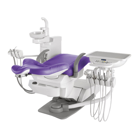
DENTAL UNIT AND CHAIR
OPERATING INSTRUCTIONS
This manual provides operating instructions for the tbCOMPASS.
The instructions contained in this booklet should be thoroughly read and
understood before operating the unit and chair.
After the installation has been completed, keep this manual in a safe place
and refer to it for future maintenance.
If you have any questions about this Manual or this product, please contact us.
If manual becomes unreadable or is lost, please request a new manual
by contacting your dealer.
Installation should be conducted by authorized personnel only.
Follow instructions on installation manual.
IMPORTANT
0197
Advertisement
Table of Contents

Related Manuals for Belmont tbCompass


Summary of Contents for Belmont tbCompass
- Page 1 DENTAL UNIT AND CHAIR OPERATING INSTRUCTIONS IMPORTANT This manual provides operating instructions for the tbCOMPASS. The instructions contained in this booklet should be thoroughly read and understood before operating the unit and chair. After the installation has been completed, keep this manual in a safe place and refer to it for future maintenance.
-
Page 2: Table Of Contents
900 dental light (Type AL-920PAS)(optional) Cleaning of vacuum /saliva ejector hose 300LED dental light (Type AL-320PAS)(optional) Cleaning of Belmont 77 syringe Right/Left Handed Dentistry Conversion Sterilization of Belmont 77 syringe Confirm before convert Junction Box Section Right/Left handed dentistry conversion... -
Page 3: Intended Use Of The Product
Medical Device Directive 93/42/EEC, RoHS Directive 2011/65/EU. Important Notes In case of the troubles, please contact Takara Belmont offices or your dealers. Do not disassemble or attempt to repair. Disassembly, repair or modifications should only be done by a qualified repair technician. -
Page 4: Symbols
SYMBOLS SYMBOLS In this manual, on the labels, on the control panels of tbCOMPASS, following symbols are used. Symbol Description Symbol Description Symbol Description Symbol Description OFF (power) Serial number Syringe ON (power) Fiber optic Micro motor Rotation mode Handpiece coolant... - Page 5 SAFETY Severity and degree of imminence of possible injury or damage This symbol indicates that “ignorance of these precautions may lead to severe WARNING injury or even death as a result of improper use.” This symbol indicates that “ignorance of these precautions may lead to mild or moderate physical injury or damage to property as a result of improper use.”...
-
Page 6: Safety Precautions
SAFETY PRECAUTIONS (Please observe safety precautions fully) WARNING 4. Be sure to establish a grounding connection Be sure to establish a proper grounding connection. (Refer to a vendor for grounding connection.) Failure or electric leakage may lead to electric shock. 5. - Page 7 Portable RF communications equipment (including peripherals such as antenna cablesand external antennas) should be used no closer than 30 cm(12 inches) to any part of the tbCOMPASS,including cables specified by the manufacturer.Otherwise,degradation of the performance of this equipment could result.
- Page 8 SAFETY PRECAUTIONS (Please observe safety precautions fully) CAUTION 1. Only experienced personnel should use this product Only dentists or other dental professionals should use this product. 2. Confirm safety before use Before use, confirm that the parts are correctly and safely operating and that there are no obstacles around this product.
- Page 9 SAFETY PRECAUTIONS (Please observe safety precautions fully) CAUTION 14. Use dental paper cups (Optional sensor cupfiller) Use dental paper cups for sensor cupfiller (optional). If the cup is another material grade (such as stainless steel and plastics) or if the paper cup is of dark color or pattern, which the sensing cup filling sensor may not respond. 15.
- Page 10 SAFETY PRECAUTIONS (Please observe safety precautions fully) CAUTION 22. Pay attention to contact injury during automatic operation of the dental unit Pay special attention to surroundings during automatic operation of the dental treatment table. Damage to the backrest, stool or Doctor's table may occur. Confirm that the patient is seated in the proper position and keep your eyes on the patient during operation.
- Page 11 SAFETY PRECAUTIONS (Please observe safety precautions fully) CAUTION 31. Precautions for right/left handed conversion • Make sure read through pages 36~41 for instructions before perform with right and left handed conversion. This could cause physical injury or property damage. • Take care not to contact the doctor table to the cuspidor during conversion. •...
- Page 12 SAFETY PRECAUTIONS (Please observe safety precautions fully) NOTICE 1. Check operation of the compressor With no air supplied, this product does not operate even after turning on the main switch. Turn on the power of the compressor before operating this product. 2.
- Page 13 SAFETY PRECAUTIONS (Please observe safety precautions fully) Caution Points During Operation of the Product Description of Symbol Marks Caution areas such as moving parts, rotating parts and detachable parts to which caution should be paid. Caution areas that are provided with an emergency stop mechanism. Be aware of contact with the assistant’s Take care not to be trapped by moving parts of instrument holder.
-
Page 14: Practice Of Flush Out
PRACTICE OF FLUSH OUT Precautions for water quality CAUTION eces. After this unit has not een use for a lo rio of (at the e innin of the w in the water in the hose the unit or water heater will create an where w. -
Page 15: Overview And Major Components 11
OVERVIEW AND MAJOR COMPONENTS Overview and Major Components (Standard Package) Spittoon Cuspidor Unit Section [Glass or ceramic (optional)] Assistant’ s Holder Doctor Table Armrest Backrest Headrest Foot Controller Doctor Unit Section Doctor Arm Overview and Major Components (Vacuum Package) Doctor Unit Section Doctor Table Doctor Arm Assistant’... - Page 16 OVERVIEW AND MAJOR COMPONENTS Doctor Unit Section Holder Type Place Holder Type Tray Mat (Optional) Tray Mat (Optional) Doctor Control Panel Doctor Control Panel Handle Handle Doctor Instruments Holder Doctor Instruments Holder (Place Holder Type) (Holder Type) Cuspidor Unit Section Sensor Cupfiller (optional) Cuspidor Maintenance Assistant Control Panel...
- Page 17 OVERVIEW AND MAJOR COMPONENTS Vac Pac Section (Vacuum Package) Height Adjustable Assistant Arm Lock release button Assistant Holder Vacuum Roller (Optional) Solid Collector Junction Box Section Water main valve (inside junction box) Turn clockwise to open and counter-clockwise to close. Water Master Valve Fuse Holder Drain valve...
-
Page 18: Description Of Operation And Functions Of Components 14
DESCRIPTION OF OPERATION AND FUNCTIONS OF COMPONENTS Chair Section Main Switch (Chair Section) Turn on the main switch located on the left side of the pump cover. A green lamp in the main switch will illuminate. • Operate the main switch by hand only. FUSE F5A/250V •... -
Page 19: Single Articulating Headrest (Optional)
DESCRIPTION OF OPERATION AND FUNCTIONS OF COMPONENTS Chair Section Single Articulating Headrest (Optional) 1 Height Adjustment Headrest Lever Hold the headrest bar with both hands and adjust headrest height by pulling out or pressing down on the headrest bar. Headrest Cover 2 Angle Adjustment Push the headrest to forward as required. - Page 20 DESCRIPTION OF OPERATION AND FUNCTIONS OF COMPONENTS Chair Section Manual Switch • Operating instruction for chair manual operation Pressing will move the chair up Pressing will move the chair down Pressing will move the backrest reclining Pressing will move the backrest raising * The chair is moving while pressing a switch.
-
Page 21: Doctor Unit Section
• A few seconds later, Lit in green BELMONT " BELMONT " is displayed and all the functions can be operated. If any error arises to the memory, the buzzer sounds and [EEPROM READ ERR] is displayed on the indicator. -
Page 22: Handpiece
DESCRIPTION OF OPERATION AND FUNCTIONS OF COMPONENTS Doctor Unit Section Handpiece Holder Type • The handpiece is actuated by picking it up from the instrument holder and operating the foot controller. Handpiece See pages 26 for operation of foot controller, micromotor and electric scaler. -
Page 23: Description Of Doctor Control Panel
DESCRIPTION OF OPERATION AND FUNCTIONS OF COMPONENTS Doctor Unit Section Description of doctor control panel An overview of display on the doctor control panel and each switch on this doctor control panel is shown in the figure below. For detailed operating instruction, please see pages 19-26. Each switch on the doctor control panel provides multiple functions, and various actions can be set when combined with the function switch. - Page 24 DESCRIPTION OF OPERATION AND FUNCTIONS OF COMPONENTS Doctor Unit Section Chair manual switch Switches for manual up/down/backrest reclining of the chair. Press will move the chair up. Press will move the chair down Press will recline the backrest. Press will return the backrest. *The chair is moving while pressing a switch.
- Page 25 DESCRIPTION OF OPERATION AND FUNCTIONS OF COMPONENTS Doctor Unit Section Cancellation Function During automatic movement (1,2,0,LP) by depress of following switches, the automatic movement will be cancell and stopped immediately. Doctor control panel To stop the chair automatic movement, press any of switches surrounded by dotted lines.
- Page 26 DESCRIPTION OF OPERATION AND FUNCTIONS OF COMPONENTS Doctor Unit Section Cuspidor bowl flush switch • When this switch is pressed, water comes out of the bowl flush nozzle and flushes the cuspidor bowl. • The timer is set for about 6 seconds. •...
- Page 27 DESCRIPTION OF OPERATION AND FUNCTIONS OF COMPONENTS Doctor Unit Section Spray on/off switch • Switch for on/off the handpiece coolant spray. • When a handpiece is picked up and this switch is pressed, either LED A (air) or LED W (water) located on the left- A •...
- Page 28 DESCRIPTION OF OPERATION AND FUNCTIONS OF COMPONENTS Doctor Unit Section Micromotor forward/reverse select switch • Use this switch for switching the micromotor rotation direction. Pressing this switch each time changes the direction between forward (clockwise) rotation and reverse For forward turning For reverse turning (counter-clockwise) rotation.
- Page 29 DESCRIPTION OF OPERATION AND FUNCTIONS OF COMPONENTS Doctor Unit Section Function switch • Use this switch for setting various working conditions. The setup function changes in the sequence indicated below each time when this switch is pressed. 1. Dental timer time setup and motion 2.
-
Page 30: Operation And Display Of Micromotor
DESCRIPTION OF OPERATION AND FUNCTIONS OF COMPONENTS Doctor Unit Section Operation and display of micromotor There are two modes available, limit rotation (limit mode) and preset rotation (preset mode) for micromotor rotation. Either one of these modes can be selected by pressing this switch. -
Page 31: Panorama Size Film Viewer (Optional)
DESCRIPTION OF OPERATION AND FUNCTIONS OF COMPONENTS Doctor Unit Section Table Height Adjustment • Hold and slightly lift up the doctor table and front arm, remove the collar to up side, lock ring will come up on the front arm post . •... -
Page 32: Water Tank (Optional)
DESCRIPTION OF OPERATION AND FUNCTIONS OF COMPONENTS Doctor Unit Section Water Tank (Optional) • Put water into the water tank and it can be supplied water from the water tank. • When the pressurization ON-OFF switch is moved in the direction of the arrow, the water tank may be used. -
Page 33: Cuspidor Unit Section
DESCRIPTION OF OPERATION AND FUNCTIONS OF COMPONENTS Cuspidor Unit Section Maintenance Panel & Cuspidor Control Panel Standard Package / Cuspidor Package Cuspidor maintenance panel Assistant panel Knurlet-screw The cuspidor maintenance panel can be opened outward by loosen the knurlet-screw from bottom of the cuspidor unit. Vacuum Package 1 Dental light select switch •... - Page 34 DESCRIPTION OF OPERATION AND FUNCTIONS OF COMPONENTS Cuspidor Unit Section 2 Service outlet (air) (Optional) Use this outlet to supply air to external equipment. 3 Service outlet (water) (Optional) Use this outlet to supply water to external equipment. 4 Water heater switch (Optional) O F F Switch for turning on/of CAUTION...
-
Page 35: Vacuum Handpiece
DESCRIPTION OF OPERATION AND FUNCTIONS OF COMPONENTS Cuspidor Unit Section Vacuum handpiece • Suction begins when the vacuum handpiece is taken out of Vacuum Tip the holder. (option) • In case of the central vacuum system, suction will not stop Open immediately after the vacuum handpiece was returned to the assistant holder, but suction will continue for about 3 seconds... -
Page 36: Height Adjustable Assistant Arm (Optional)
DESCRIPTION OF OPERATION AND FUNCTIONS OF COMPONENTS Cuspidor Unit Section Ratchet type assistant arm Height adjustment of an assistant arm (Option Push up the assistant holder to the desired height position. Lock release button Press the lock release button and bring down the assistant holder to the desired height and release the lock button. -
Page 37: Dental Light Section
DESCRIPTION OF OPERATION AND FUNCTIONS OF COMPONENTS Dental Light Section 701 dental light (Type AL-720PAS)(Optional) Main switch and operation switch • When the main switch of the dental unit is turned on, the indicator shown in the figure is lit in green or orange and the dental light power is turned on. -
Page 38: Dental Light (Type Al-920Pas)(Optional)
DESCRIPTION OF OPERATION AND FUNCTIONS OF COMPONENTS Dental Light Section 900 dental light (Type AL-920PAS)(Optional) LED display Main switch and operation switch When the main switch of the dental unit is turned on, the indicator shown in the figure is lit in green and the dental light power is turned on. -
Page 39: 300Led Dental Light (Type Al-320Pas)(Optional)
DESCRIPTION OF OPERATION AND FUNCTIONS OF COMPONENTS Dental Light Section 300LED dental light (Type AL-320PAS)(Optional) Main switch and operation switch When the main switch of the dental unit is turned on, the dental light power also turned on. Intensity control volume The dental light may be turned on and off with the touchless switch or the dental light switch... -
Page 40: Right/Left Handed Dentistry Conversion
DESCRIPTION OF OPERATION AND FUNCTIONS OF COMPONENTS Right/Left handed dentistry conversion re convert to right or left handed position • Bring the chair to the upper position and backrest upright position. • Turn off the main switch for safety. CAUTION Take care not to contact other people or to the unit during the work. -
Page 41: Right/Left Handed Dentistry Conversion
DESCRIPTION OF OPERATION AND FUNCTIONS OF COMPONENTS Right/Left handed dentistry conversion Swing the doctor table to the cuspidor side as shown on left CAUTION Be carefully when moving the doctor table. Not to contact the doctor table with the cuspidor unit. Remove the swing bracket cover by pulling as direction of the arrow from behind the chair Pull up the lock lever A on the swing arm, then swing the swing arm slightly to... - Page 42 DESCRIPTION OF OPERATION AND FUNCTIONS OF COMPONENTS Right/Left handed dentistry conversion At that the vacuum hose and saliva ejector hoses may be Swing the cuspidor unit and the assistant holder as shown on the left When the cuspidor unit moved to correct position as shown on the left the lock lever A on the swing bracket can be locked automatically...
- Page 43 DESCRIPTION OF OPERATION AND FUNCTIONS OF COMPONENTS Right/Left handed dentistry conversion Attach the swing bracket cover to swing bracket. NOTICE The swing bracket cover is same for left and right. Turn it upside down and attach to it. Pull the lock lever C on the swing arm bracket, then swing the light pole slightly to chair legrest side.
- Page 44 DESCRIPTION OF OPERATION AND FUNCTIONS OF COMPONENTS Right/Left handed dentistry conversion After moved the light pole, the balance arm position become A position as shown on the left figure. Adjust the position of the After this conversion, be sure to confirm the safety function has been working properly.
-
Page 45: Confirm The Safety Function
DESCRIPTION OF OPERATION AND FUNCTIONS OF COMPONENTS Right/Left handed dentistry conversion Confirm the safety function For safe use of this product, Please confirm safety function as follows after every this conversion. The safety mechanism that inhibits chair motion works while of the following actions is taken. -
Page 46: Operation Setting 42
OPERATION SETTING Chair Auto Operation Setting Preset position setup procedures Set the treatment position by chair 1. Move the chair to the treatment position using manual manual switch switches. 2. Upon deciding of the desired treatment position, keep pressing preset switch , to be set for about 5 seconds. -
Page 47: Doctor Unit Section
OPERATION SETTING Doctor Unit Section Contents and sequence of function switch Indicator Function Switch • The contents of display on the indicator on the doctor control panel change sequentially each time when the function switch is pressed to select a desired setup. Contents and sequence of function switch setup are described below. Setup and operation of dental timer Selection of doctor number Selection and operation of flushout... -
Page 48: Dental Timer
OPERATION SETTING Doctor Unit Section Setup of dental timer and operation • A countdown timer is built in to the unit and can be set to a maximum timer of 90 minutes and 50 seconds in 1 minute or = 01:10 10 second increments. -
Page 49: Doctor Number
OPERATION SETTING Doctor Unit Section 2 Selection of doctor number • Chair positions and handpiece initial setup for four different doctors can be stored. ◎ Micromotor preset rotation speed, and on/off statue of light pack and spray. (3 positions per each doctor) ◎... -
Page 50: Key Touch Tone
OPERATION SETTING Doctor Unit Section 4 Selection and change of key touch tone With or without beep tone that is issued when a switch is pressed can be selected, and the beep tone frequency (tone quality) can be changed. (It is not possible to control the volume of the selected (Example) Case of with switch tone frequency.) Tone off... -
Page 51: Alarm Tone
OPERATION SETTING Doctor Unit Section 6 Selection of alarm sound for dental timer • The alarm sounds on termination of timer time after countdown of dental timer. PUSH • Four alarm patterns are provided, and even in case where multiple chairs are installed in the same room, the chair from which the alarm sounds can be easily identified if different alarm patters are set. -
Page 52: Interlocked Action Of Cupfiller And Bowl Flush
OPERATION SETTING Doctor Unit Section 9 Selection of interlocked action of cupfiller and bowl • Selection is permitted from two procedures. ◎ Case of non-interlock (Example) Case of interlock Flushout of the cuspidor bowl is not implemented even after Interlock Non-interlock ◎... -
Page 53: Displaying The Micromotor Gear Ratio
OPERATION SETTING Doctor Unit Section Function of calculating and displaying the Keep pressing micromotor gear ratio • This setting function converts the gear ratio of the contra- angle handpiece to be mounted to the micromotor and displays values near the actual revolutions. •... -
Page 54: Recurrence Mode At The Time Of Power On And Setup
OPERATION SETTING Doctor Unit Section Description of recurrence mode at the time of power on and setup • This recurrence mode is the rotation mode that always appears first when a micromotor is picked up after the main switch is turned on. Save frequently-used mode •... -
Page 55: Operation Stopping Function
OPERATION STOPPING FUNCTION Chair motion stop function (safety function) The safety mechanism that inhibits chair motion works while any of the following actions is taken. The "LOCK" Lit in Orange LED indicator lamp is lit in orange in this state. LOCK... -
Page 56: Adjustment Of Parts
ADJUSTMENT OF PARTS Junction Box Section Main air pressure reducing valve Knob • This knob adjusts the main pressure of air supplied to the Increase Decrease unit. • Pull the knob and turn as shown in the drawing so that the Pull up main air pressure gauge reads a value between 0.45 and 0.5 MPa. -
Page 57: Care And Maintenance 53
CARE AND MAINTENANCE Chair Section Chair Surface Cleaning and Disinfection • The surface of the chair’s seating area is made of synthetic leather. Apply dry wiping, wipe the surface with wet cloth or moistened with a 10% detergent solution diluted using water. In case the synthetic leather is wiped with a wet cloth, fully wipe off the moisture with dry cloth. -
Page 58: Doctor Unit Section
CARE AND MAINTENANCE Doctor Unit Section Tray mat (Option) Doctor control panel Doctor Instruments holder Tray mat (Optional) • The tray mat may be detached and sterilized in an autoclave (for 20 minutes at 121°C or 12 minutes at 132°C). Remove residues and clean carefully with running water before sterilization. -
Page 59: Doctor Instrument Holder
CARE AND MAINTENANCE Doctor Unit Section Doctor Instrument holder • Use FD333 or FD366 made by Durr or ethanol as sprayed to a soft cloth for cleaning and disinfection. Wipe off with dry soft cloth to dried up of the instrument holder after cleaning and disinfection. -
Page 60: Cuspidor Unit Section
CARE AND MAINTENANCE Cuspidor Unit Section Assistant control panel • Use FD333 or FD366 made by Durr or ethanol as sprayed to a soft cloth for cleaning and disinfection. Wipe off with dry soft cloth to dried up of the assistant control panel. CAUTION •... -
Page 61: Cleaning Of Spittoon Section
CARE AND MAINTENANCE Cuspidor Unit Section Cleaning of spittoon section • Use MD550 made by Durr to cleaning the spittoon bowl. Cupfiller base Detach the spittoon bowl according to the following Drain cap procedures. 4 Basket 3. Remove the (3) drain cap and pull out the (4) basket strainer Cupfiller strainer. -
Page 62: Cleaning Of Vacuum / Saliva Ejector Handpiece
CARE AND MAINTENANCE Cuspidor Unit Section Cleaning of Vacuum Handpiece / Saliva Ejector Handpiece • For effective sterilization, washing for removing contamination and immersion by a cleaning agent are required. Then, rinse by water in order to remove residual Vacuum Tip cleaning agent on medical device. -
Page 63: Sterilization Of Vacuum / Saliva Ejector Handpiece
CARE AND MAINTENANCE Cuspidor Unit Section Sterilization of vacuum / saliva ejector handpiece Caution when assembling Sterilization must be done every after use to patients.Vacuum vacuum handpiece before Tip/Vacuum Cap/ Vacuum Handpiece Body/Saliva Ejector sterilization Handpiece Body can be autoclave. Vacuum handpiece body and saliva ejector body have to assemble before autoclave. -
Page 64: Cleaning Of The Solid Collector
CARE AND MAINTENANCE Cuspidor Unit Section Cleaning of the solid collector Detach and wash the filter in the solid collector of the Solid collector Cuspidor unit at the end of each work day. If sucked substances are collected, the suction force of the vacuum is reduced. -
Page 65: Cleaning Of Belmont 77 Syringe
CARE AND MAINTENANCE Cuspidor Unit Section Cleaning of Belmont 77 syringe [Disassembly] Syringe body Remove the nozzle from syringe by turning it in direction A. [Cleaning by hand] 1.Wipe off the surface contamination by a cloth while rinsing the surface by running clean warm water at 40±5 ℃. -
Page 66: Junction Box Section
CARE AND MAINTENANCE Junction Box Section Cleaning air lter drain valve and discharging water from air compressor • Drain valve is used to dischar • Turn the drain valve counterclockwise to discharge water Maintenance Lid • If water enters the unit, the air turbine, air motor or syringe, Pump cover etc., may become defective. -
Page 67: Care Storage, Lifetime, Disposal And Restrictions Of Use
CARE STORAGE, LIFETIME, DISPODAL AND RESTRICTIONS OF USE Storage method Strictly observe the following points when the product will not be used for a long period of time (following the completion of work, during the suspension of business, etc.). 1.Main switch •... -
Page 68: Before Asking For Repairs
BEFORE ASKING FOR REPAIRS If any of phenomena described below has occurred, make the following checks before asking for repairs. Phenomenon Check point and result Action to be taken Main switch is not on. Turn on the main switch. The product does not Air compressor power is not on. -
Page 69: Dimensions And Specifications 65
DIMENSIONS AND SPECIFICATIONS Standard Package ( Chair + Doctor Unit + Cuspidor Unit ) Rated power supply : 230 VAC, 50/60 Hz, 3.5/3.5A Fuse : 5A/250V(Current Rating:50A at 250VAC) Fast blow Size of Fuse (5 x 20mm) Weight : 185kg Maximum Load : Patient capacity 135kg Load capacity... - Page 70 DIMENSIONS AND SPECIFICATIONS Doctor Package ( Chair + Doctor Unit ) Rated power supply : 230 VAC, 50/60 Hz, 3.5/3.5A Fuse : 5A/250V(Current Rating:50A at 250VAC) Fast blow Size of Fuse (5 x 20mm) Weight : 155kg Maximum Load : Patient capacity 135kg Load capacity : Doctor table 3kg Classification of foot controller...
- Page 71 DIMENSIONS AND SPECIFICATIONS Cuspidor Package ( Chair + Cuspidor Unit ) Rated power supply : 230 VAC, 50/60 Hz, 3.5/3.5A Fuse : 5A/250V(Current Rating:50A at 250VAC) Fast blow Size of Fuse (5 x 20mm) Weight : 160kg Maximum Load : Patient capacity 135kg Classification of foot controller : IPX1(applicable standard IEC60529) Protection class against electric shock...
- Page 72 DIMENSIONS AND SPECIFICATIONS Vacuum Package ( Chair + Doctor Unit + Vac Pac ) Rated power supply : 230 VAC, 50/60 Hz, 3.5/3.5A Fuse : 5A/250V(Current Rating:50A at 250VAC) Fast blow Size of Fuse (5 x 20mm) Weight : 170kg Maximum Load : Patient capacity 135kg Load capacity...
-
Page 73: Maintenance And Inspection 69
MAINTENANCE AND INSPECTION Guide for daily maintenance and inspection (Maintenance and inspection by user) Management of maintenance and inspection of medical equipment should be implemented by the user (medical institution). In case the user does not implement such management, it is permitted that such management is outsourced to a qualified entity such as a medical equipment repair company. - Page 74 MAINTENANCE AND INSPECTION Inspection method Influence if inspection Maintenance required in case Item Frequency and diagnosis not conducted of nonconformity Execute care in accordance with Matters After Excessive handpiece oil or The motor section will the instruction manual attached to attached to closing the like shall not be attached...
- Page 75 MAINTENANCE AND INSPECTION Guide for Periodical Check-up Some parts and components of the products are degraded or deteriorated depending on the frequency of use. Annual check-up and maintenance, as well as replacement of consumable parts, are required. The required parts (including consumable parts) are listed below. It may be different from the following list depending on the option of the unit.
-
Page 76: List Of Compatible Handpieces
LIST OF COMPATIBLE HANDPIECES Air motor Scaler Syringe Turbine Micromotor BIEN AIR BIEN AIR BTK 77 TYPE Aquilon 830/ VARIOS170 Ti-Max X UNIFIX/w/Light /PM1132 BIEN AIR FARO 3WAY NEWTRON LED/ MACH-LITE XT EX-203/EX-6 DMCX+MCX SP4055 NEWTRON Module + LED Drive Board LUZZANI 3WAY PANA-MAX... -
Page 77: Electromagnetic Compatibility (Emc) 73
4. Electromagnetic emission declaration Guidance and manufacturer’s declaration – electromagnetic emissions The tbCOMPASS is intended for use in the electromagnetic environment specified below. The customer or user of the tbCOMPASS should ensure that it is used in such an environment. - Page 78 WARNING Portable RF communications equipment (including peripherals such as antenna cablesand external antennas) should be used no closer than 30 cm(12 inches) to any part of the tbCOMPASS,including cables specified by the manufacturer. Otherwise,degradation of the performance of this equipment could result.
-
Page 79: Declaration Of Conformity
Directive: 93/42/EEC and RoHS Directive: 2011/65/EU based on category 8 of Annex I. Product : DENTAL UNIT AND CHAIR (CLASS IIa) Model : tbCOMPASS The product has been designed and manufactured in accordance with the European standards as the listed in the... - Page 80 TAKARA COMPANY EUROPE GmbH TAKARA BELMONT CORPORATION Berner Strasse 18, 60437 Frankfurt am Main, Germany 2-1-1, Higashishinsaibashi,Chuo-ku,Osaka, 542-0083,Japan Tel:+49 69 506878 0 TEL : +81 6 6213 5945 FAX : +81 6 6212 3680 Fax:+49 69 506878 20 BOOK NO. 1A0AAKPE...
Need help?
Do you have a question about the tbCompass and is the answer not in the manual?
Questions and answers