Table of Contents
Advertisement
Quick Links
Preface
The purpose of this publication is to provide the service
technician with information for troubleshooting, testing
and repair of major systems and components on the Pro
Sweep 5200.
REFER TO THE OPERATOR'S MANUAL FOR OPER-
ATING,
MAINTENANCE
INSTRUCTIONS. Space is provided in Chapter 2 of this
book to insert the Operator's Manual and Parts Catalog
for your machine. Additional copies of the Operator's
Manual and Parts Catalog are available on the internet
at www.Toro.com.
The Toro Company reserves the right to change product
specifications or this publication without notice.
AND
ADJUSTMENT
E The Toro Company - - 2005, 2009
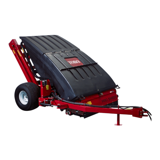
Service Manual
Pro Sweep 5200
This safety symbol means DANGER, WARNING,
or CAUTION, PERSONAL SAFETY INSTRUC-
TION. When you see this symbol, carefully read
the instructions that follow. Failure to obey the
instructions may result in personal injury.
NOTE: A NOTE will give general information about the
correct operation, maintenance, service, testing or re-
pair of the machine.
IMPORTANT: The IMPORTANT notice will give im-
portant instructions which must be followed to pre-
vent damage to systems or components on the
machine.
Part No. 05137SL (Rev. A)
Advertisement
Chapters
Table of Contents
Troubleshooting

Related Manuals for Toro Pro Sweep 5200


Summary of Contents for Toro Pro Sweep 5200
- Page 1 NOTE: A NOTE will give general information about the correct operation, maintenance, service, testing or re- The Toro Company reserves the right to change product pair of the machine. specifications or this publication without notice. IMPORTANT: The IMPORTANT notice will give im-...
- Page 2 This page is intentionally blank. Pro Sweep 5200...
-
Page 3: Table Of Contents
Special Tools ......5 – 1 Securing Pro Sweep 5200 to Tow Vehicle ..1 – 5 Troubleshooting . - Page 4 This page is intentionally blank. Pro Sweep 5200...
- Page 5 JACKING INSTRUCTIONS ..... 4 SECURING PRO SWEEP 5200 TO TOW VEHICLE 5 SAFETY AND INSTRUCTION DECALS ..5 Pro Sweep 5200 Page 1 –...
-
Page 6: Safety Instructions
Safety Instructions The Pro Sweep 5200 is designed and tested to offer safe service when operated and maintained properly. WARNING Although hazard control and accident prevention par- tially are dependent upon the design and configuration To reduce the potential for injury or death, of the machine, these factors are also dependent upon comply with the following safety instructions. -
Page 7: Maintenance And Service
Toro replacement parts and ac- 4. Keep body and hands away from pin hole leaks in hy- cessories. Replacement parts and accessories made draulic lines that eject high pressure hydraulic fluid. -
Page 8: Jacking Instructions
(Fig. 1). Do not use the axle as a jacking point. 3. Carefully jack machine off the ground. 4. Position jack stands or hardwood blocks under the main frame to support the sweeper. Page 1 – 4 Safety Pro Sweep 5200... -
Page 9: Securing Pro Sweep 5200 To Tow Vehicle
Safety and Instruction Decals Numerous safety and instruction decals are affixed to the Pro Sweep 5200. If any decal becomes illegible or damaged, install a new decal. Part numbers for replace- ment decals are listed in your Parts Catalog. Order re- placement decals from your Authorized Toro Distributor. - Page 10 This page is intentionally blank. Page 1 – 6 Safety Pro Sweep 5200...
-
Page 11: Product Records
Operator’s Manuals and Parts Catalogs for those options at the end of this chapter. Maintenance Maintenance procedures and recommended service in- tervals for the Pro Sweep 5200 are covered in the Oper- ator’s Manual. Refer to that publication when performing regular equipment maintenance. Pro Sweep 5200 Page 2 –... -
Page 12: Equivalents And Conversions
Equivalents and Conversions 0.09375 Page 2 - - 2 Rev. A Product Records and Maintenance Pro Sweep 5200... -
Page 13: Torque Specifications
For critical applications, as determined reduced by 25% for lubricated fasteners to achieve by Toro, either the recommended torque or a torque that the similar stress as a dry fastener. Torque values may is unique to the application is clearly identified and spe- also have to be reduced when the fastener is threaded cified in this Service Manual. -
Page 14: Standard Torque For Dry, Zinc Plated And Steel Fasteners (Inch Series)
The specific torque value should be determined based on the fastener size, the aluminum or base material strength, length of thread engagement, etc. Page 2 - - 4 Rev. A Product Records and Maintenance Pro Sweep 5200... -
Page 15: Standard Torque For Dry, Zinc Plated And Steel Fasteners (Metric Fasteners)
The specific torque value should be determined based on the fastener size, the aluminum or base material strength, length of thread engagement, etc. Pro Sweep 5200 Page 2 – 5 Product Records and Maintenance... -
Page 16: Other Torque Specifications
All torque values are based on non–lubricated fasteners. Conversion Factors in–lb X 11.2985 = N–cm N–cm X 0.08851 = in–lb ft–lb X 1.3558 = N–m N–m X 0.7376 = ft–lb Page 2 – 6 Product Records and Maintenance Pro Sweep 5200... - Page 17 Lift Cylinder Service ......24 PARKER TORQLINK SERVICE PROCEDURE Pro Sweep 5200 Page 3 – 1 Hydraulic System...
-
Page 18: General Information
6 (3/8 in.) 0.75 + 0.25 8 (1/2 in.) 0.75 + 0.25 10 (5/8 in.) 1.00 + 0.25 Figure 2 12 (3/4 in.) 0.75 + 0.25 16 (1 in.) 0.75 + 0.25 Hydraulic System Page 3 – 2 Pro Sweep 5200... - Page 19 6 (3/8 in.) 1.50 + 0.25 8 (1/2 in.) 1.50 + 0.25 10 (5/8 in.) 1.50 + 0.25 12 (3/4 in.) 1.50 + 0.25 Figure 6 16 (1 in.) 1.50 + 0.25 Pro Sweep 5200 Page 3 – 3 Hydraulic System...
- Page 20 OFF and remove key from the igni- tion switch. Securing Sweeper to Tow Vehicle (Fig. 7) While servicing the Pro Sweep 5200, make sure that the hitch pin is properly positioned in tow vehicle hitch and sweeper tongue. Hitch pin should be secured with hair- pin clip.
-
Page 21: Hydraulic Schematic
Hydraulic Schematic LIFT CYLINDER CONTROL MANIFOLD BRUSH MOTOR 2.7 CI/REV Pro Sweep 5200 Hydraulic Schematic All solenoids are shown as de–energized Pro Sweep 5200 Page 3 – 5 Hydraulic System... -
Page 22: Hydraulic Flow Diagrams
Hydraulic Flow Diagrams LIFT CYLINDER (ENERGIZED) (ENERGIZED) CONTROL MANIFOLD BRUSH MOTOR 2.7 CI/REV Brush Circuit (Brush Rotating Shown) Working Pressure Return Flow Hydraulic System Page 3 – 6 Pro Sweep 5200... - Page 23 (S2) to return to the tow vehicle through control manifold and returns to the tow vehicle. port T and the return to tank hose. NOTE: The hopper must be lowered for the Pro Sweep 5200 brush to operate. Pro Sweep 5200 Page 3 – 7 Hydraulic System...
-
Page 24: Hopper Dump/Lower Circuits
CYLINDER (ENERGIZED) (EXTENDING) (ENERGIZED) CONTROL MANIFOLD HOPPER DUMP BRUSH MOTOR 2.7 CI/REV LIFT CYLINDER (RETRACTING) (ENERGIZED) CONTROL MANIFOLD HOPPER LOWER BRUSH MOTOR 2.7 CI/REV Hopper Dump/Lower Circuits Working Pressure Return Flow Hydraulic System Page 3 – 8 Pro Sweep 5200... - Page 25 S4 will de–energize and oil flow from the lift inder extension. cylinder will cease. The hopper will remain in the partial- ly lowered position. Pro Sweep 5200 Page 3 – 9 Hydraulic System...
-
Page 26: Troubleshooting
The successful operation of the Pro Sweep 5200 de- pends on the hydraulic system of the tow vehicle. When A hydraulic system with an excessive increase in heat or noise has a potential for failure. - Page 27 Á Á Á Á Á Á Á Á Á Á Á Á Á Á Á Á Á Á Á Á Á Á Á Á Á Á Á Á Á Á Á Á Á Á Á Pro Sweep 5200 Page 3 – 11...
- Page 28 This page is intentionally blank. Hydraulic System Page 3 – 12 Pro Sweep 5200...
-
Page 29: Service And Repairs
If fluid is in- jected into the skin, it must be surgically re- moved within a few hours by a doctor familiar with this type of injury. Gangrene may result from such an injury. Pro Sweep 5200 Page 3 – 13 Hydraulic System... -
Page 30: Brush Motor
17. Flange bearing (2 used) 5. Lock nut (2 used) 12. O–ring (2 used) 18. Square key 6. Flat washer (2 used) 13. Cap screw (2 used) 19. Brush 7. Carriage bolt (6 used) Hydraulic System Page 3 – 14 Pro Sweep 5200... - Page 31 3. Position and support brush motor to the frame. Make 1. Brush shaft 4. Motor coupling jaw sure to align coupling jaw on motor shaft with coupling 2. Brush coupling jaw 5. Motor shaft spider. 3. Coupling spider Pro Sweep 5200 Page 3 – 15 Hydraulic System...
-
Page 32: Brush Motor Service
6. Manifold 13. Thrust bearing 20. Seal 7. Stator 14. Thrust washer NOTE: For service of the hydraulic brush motor, see the Parker Torqlink Service Procedure at the end of this chapter. Hydraulic System Page 3 – 16 Pro Sweep 5200... - Page 33 This page is intentionally blank. Pro Sweep 5200 Page 3 – 17 Hydraulic System...
-
Page 34: Hydraulic Control Manifold
5. Clean control manifold and manifold hydraulic con- surized hydraulic oil. See Relieving Hydraulic nections. Disconnect hydraulic hoses from manifold fit- System Pressure in the General Information sec- tings. tion of this chapter. Hydraulic System Page 3 – 18 Pro Sweep 5200... - Page 35 Properly tighten all hydraulic connections (see Hydrau- lic Fitting Installation in the General Information section of this chapter). 7. Secure hydraulic manifold to machine by tightening cap screws and lock nuts. 8. Reconnect solenoid valve electrical connectors. Pro Sweep 5200 Page 3 – 19 Hydraulic System...
-
Page 36: Hydraulic Control Manifold Service
NOTE: The ports on the manifold are marked for easy identification of components. Example: P is the pump connection port (See Hydraulic Schematics to identify the function of the hydraulic lines and cartridge valves at each port). Hydraulic System Page 3 – 20 Pro Sweep 5200... - Page 37 9. After assembly, if problems still exist, remove valve there may be water in the system. and clean again or replace valve. CAUTION Use eye protection such as goggles when using compressed air for cartridge valve cleaning. Pro Sweep 5200 Page 3 – 21 Hydraulic System...
-
Page 38: Lift Cylinder
Figure 15 1. Main sweeper frame 5. Lock nut 8. O–ring 2. Lift cylinder 6. Pitch frame 9. Check valve fitting 3. Cap screw 7. Hydraulic hose 10. O–ring 4. Pivot pin Hydraulic System Page 3 – 22 Pro Sweep 5200... - Page 39 6. Support lift cylinder and slide pivot pins from the lift cylinder and machine frame. 7. Remove lift cylinder from the machine. 8. If needed, remove hydraulic check valve fitting and o–ring from the lift cylinder. Discard o–ring. Pro Sweep 5200 Page 3 – 23 Hydraulic System...
-
Page 40: Lift Cylinder Service
Remove lock nut (item 13) and carefully slide piston and head from the rod. 4. Grasp end of rod; extract rod assembly and head by carefully twisting and pulling on the rod. Rev. A Hydraulic System Page 3 - - 24 Pro Sweep 5200... - Page 41 Apply silicone sealer to barrel access slot. 2. Install new seals to the head and piston. Rev. A Pro Sweep 5200 Page 3 - - 25 Hydraulic System...
- Page 42 This page is intentionally blank. Hydraulic System Page 3 – 26 Pro Sweep 5200...
- Page 43 Solenoid Valve Coil ......11 Electrical Diagrams The electrical schematic and wire harness drawings for the Pro Sweep 5200 are located in Chapter 6 – Electrical Diagrams. Special Tools...
-
Page 44: Troubleshooting
Logic diode is faulty. Demand solenoid valve coil (S2) or circuit wiring is faulty. Brush solenoid valve coil (S3) or circuit wiring is faulty. Hydraulic problem exists (see Chapter 3 – Hydraulic System). Page 4 – 2 Electrical System Pro Sweep 5200... - Page 45 Hopper switch or circuit wiring is faulty. Hopper down solenoid valve coil (S4) or circuit wiring is faulty. Hydraulic problem exists (see Chapter 3 – Hydraulic System). Pro Sweep 5200 Page 4 – 3 Electrical System...
-
Page 46: Safety Interlock System
Safety Interlock System The safety interlock system of the Pro Sweep 5200 en- CAUTION sures that the brush will not rotate when the dump hop- per is in the raised position. Interlock system operation is described in the Pro Do not disconnect the Pro Sweep 5200 hopper down proximity switch. -
Page 47: Component Testing
Verify continuity between switch termi- nals. SWITCH NORMAL OTHER POSITION CIRCUITS CIRCUITS 2 + 3 5 + 6 2 + 1 5 + 4 BACK OF SWITCH Figure 3 Pro Sweep 5200 Page 4 – 5 Electrical System... -
Page 48: Hopper Switch
Verify continuity between switch termi- nals. SWITCH NORMAL OTHER POSITION CIRCUITS CIRCUITS BACK OF SWITCH RAISE 2 + 1 5 + 4 Figure 5 MIDDLE NONE NONE LOWER 2 + 3 5 + 6 Page 4 – 6 Electrical System Pro Sweep 5200... -
Page 49: Brush And Hopper Down Relays
Brush and Hopper Down Relays The electrical system of the Pro Sweep 5200 includes two relays: the brush relay and the hopper down relay. These relays are identical and are located in the control box enclosure. The brush relay is used to de–energize the brush motor solenoid (S3) when the hopper up/down switch is pushed to raise. -
Page 50: Fuse
Fuse The Pro Sweep 5200 uses a single 20 amp fuse for cir- cuit protection. The fuse holder is located in the wiring harness (Fig. 7). Testing Remove fuse from the fuse holder for testing. Fuse should have continuity between fuse terminals. -
Page 51: Solenoid Valve Coil
Solenoid Valve Coil The hydraulic system on the Pro Sweep 5200 uses four (4) solenoid valve coils on the hydraulic control manifold (Fig. 9). Testing NOTE: The solenoid does not have to be removed from the cartridge valve for testing. -
Page 52: Hopper Down Proximity Switch
Hopper Down Proximity Switch The Pro Sweep 5200 uses a proximity switch as an inter- lock device to prevent brush operation (rotation) when the dump hopper is raised. This switch is normally open and closes when the pitch frame moves the switch cam near the target end of the switch (dump hopper low- ered). -
Page 53: Service And Repairs
1. Solenoid valve coil (S2) 4. Solenoid valve coil (S1) 3. Connect the machine wiring harness electrical con- 2. Solenoid valve coil (S3) 5. Nut 3. Solenoid valve coil (S4) nector to the solenoid coil. Pro Sweep 5200 Page 4 – 11 Electrical System... - Page 54 This page is intentionally blank. Page 4 – 12 Electrical System Pro Sweep 5200...
- Page 55 GENERAL INFORMATION ..... 2 Securing Pro Sweep 5200 to Tow Vehicle ..2 SERVICE AND REPAIRS ..... . 3 Wheels .
-
Page 56: Specifications
70 to 90 ft–lb (95 to 122 N–m) General Information Securing Pro Sweep 5200 to Tow Vehicle While operating or servicing the Pro Sweep 5200, make sure that hitch pin is properly positioned in tow vehicle hitch and sweeper tongue. Hitch pin should be secured with hairpin clip (Fig. -
Page 57: Service And Repairs
3. Loosen and remove five (5) lug nuts from wheel to be nately torque lug nuts from 70 to 90 ft–lb (95 to 122 removed. N–m). 4. Pull wheel from sweeper. 3. Lower machine to ground. Pro Sweep 5200 Page 5 – 3 Chassis... -
Page 58: Wheel Bearings
7. Outer bearing cup 11. Slotted hex nut 3. Inner bearing cone 8. Outer bearing cone 12. Cotter pin 4. Inner bearing cup 9. Lug nut (5 used) 13. Dust cup 5. Wheel hub Chassis Page 5 – 4 Pro Sweep 5200... - Page 59 Failure to maintain proper lug nut torque could result in failure or loss of wheel and may result in personal injury. 7. Install wheel assembly (see Wheel Installation in this section). 8. Carefully lower machine to ground. Pro Sweep 5200 Page 5 – 5 Chassis...
-
Page 60: Servicing The Brush Housing
Servicing the Brush Housing RIGHT FRONT Figure 4 1. Saddle frame 3. Hydraulic brush motor 5. Brush housing 2. Roller 4. Brush Chassis Page 5 – 6 Pro Sweep 5200... - Page 61 3. Support component(s) to prevent it (them) from shift- 9. Install component(s) to machine (see Brush, Brush ing position. Housing and/or Roller in this section). Pro Sweep 5200 Page 5 – 7 Chassis...
-
Page 62: Brush
2. Remove hydraulic brush motor from brush housing (see Hydraulic Brush Motor Removal in the Service and for procedure to remove brush from brush housing. Repairs section of Chapter 3 – Hydraulic System). Re- move coupler spider (item 15). Chassis Page 5 – 8 Pro Sweep 5200... - Page 63 125 to 155 in–lb (14.1 to 17.5 2. Key 6. Square key N–m) to secure locking collar to brush shaft. 3. Coupling jaw 7. Set screw (2 per jaw) 4. Coupling spider Pro Sweep 5200 Page 5 – 9 Chassis...
-
Page 64: Brush Housing
(61 to 75 N–m) RIGHT FRONT Figure 8 1. Saddle frame 4. Flange bushing 7. Thrust washer 2. Cap screw 5. Pivot mount 8. Brush housing 3. Lock nut 6. Grease fitting (2 used) Chassis Page 5 – 10 Pro Sweep 5200... - Page 65 7. Set screw (2 per jaw) 4. Coupling spider 3. Position brush housing under raised hopper. 4. Slowly lower hopper to position brush housing to saddle frame (see Servicing the Brush Housing in this section). Pro Sweep 5200 Page 5 – 11 Chassis...
-
Page 66: Roller
13. Carriage screw (4 used) 4. Brush housing 9. Bearing (2 used) 14. Adjuster key (2 used) 5. Flange nut (10 used) 10. Lock nut (4 used) 15. Carriage screw (2 used) Chassis Page 5 – 12 Pro Sweep 5200... - Page 67 C. Remove carriage screws (item 13), flat washers (item 11) and lock nuts (item 10) that secure bearing flanges to roller adjustment plate. D. Slide bearing flanges, locking collar and bearing from roller. Pro Sweep 5200 Page 5 – 13 Chassis...
-
Page 68: Frame Assembly
Manual). and remove key from the ignition switch. Chock sweep- er wheels to prevent sweeper from moving. 2. Disassemble frame as needed using Figure 11 as a guide. Chassis Page 5 – 14 Pro Sweep 5200... - Page 69 Control Box Wire Harness ....8 Power Wire Harness ......9 Pro Sweep 5200 Page 6 – 1...
- Page 70 This page is intentionally blank. Electrical Diagrams Page 6 – 2 Pro Sweep 5200...
-
Page 71: Electrical Schematic
Pro Sweep 5200 Electrical Schematic Relays are shown as de–energized All ground wires are black. Page 6 – 3... -
Page 72: Brush Circuit
(HOPPER DOWN) (ENERGIZED) (ENERGIZED) (NOT ENERGIZED) (ENERGIZED) Pro Sweep 5200 Brush Circuit Power Current Control Current Indicator Current Page 6 – 4... -
Page 73: Hopper Dump Circuit
(HOPPER RAISING) (ENERGIZED) (NOT ENERGIZED) (ENERGIZED) (ENERGIZED) Pro Sweep 5200 Hopper Dump Circuit Power Current Control Current Indicator Current Page 6 – 5... -
Page 74: Hopper Lower Circuit
(HOPPER LOWERING) (NOT ENERGIZED) (NOT ENERGIZED) (ENERGIZED) Pro Sweep 5200 Hopper Lower Circuit Power Current Control Current Indicator Current Page 6 – 6... -
Page 75: Main Wire Harness
PINK YELLOW GRAY BLACK BLACK Pro Sweep 5200 Main Wire Harness Page 6 – 7... -
Page 76: Control Box Wire Harness
YELLOW ORANGE BLACK BLACK PINK PINK PINK BLACK BLUE BROWN GRAY YELLOW BLACK GREEN VIOLET Pro Sweep 5200 Control Box Wire Harness Page 6 – 8... -
Page 77: Power Wire Harness
VEHICLE GROUND MAIN HARNESS VEHICLE POWER BRAKE CONTROL HARNESS BLUE VEHICLE GROUND BLACK MAIN HARNESS VEHICLE POWER FUSIBLE LINK Pro Sweep 5200 Power Wire Harness Page 6 – 9...